
1.Overview
The supercapacitor energy storage power supply for trams or trolleybuses is composed of hundreds of individual supercapacitors in series and parallel. The energy storage power supply is generally composed of modules connected in series, and modules are connected in series with 6 or 8 parallel sections. Extending the service life of supercapacitor monomers is the key to extending the service life of energy storage power supplies.
Due to the differences in leakage characteristics and capacity of supercapacitors, voltage differences between series connections will occur in energy storage power supply applications. Over time, the voltage difference will become larger and larger. Inconsistent voltage in series connection may cause high voltage in the charging and discharging process, leading to individual damage and affecting the service life of the supercapacitor energy storage power supply, resulting in voltage balance.
This article discusses a mode of voltage balancing, with the main balancing control parameter being module voltage, dedicated to voltage consistency balancing between modules. Because this balancing mode focuses on the early stages of system startup, it is called boot balancing.
The inconsistent leakage parameters (fundamentally individual parameters) of the supercapacitor module can lead to inconsistent module voltage, which increases the balancing burden of the supercapacitor energy storage power supply during the charging and discharging process. The purpose of startup balancing is to reduce this burden. At startup, the voltage inside the energy storage power supply is balanced to ensure that the voltage consistency of each module is as acceptable as possible before entering the charging and discharging process of the energy storage power supply.
2. Power on balancing principle
Each module of the supercapacitor energy storage power supply is equipped with a voltage balancing unit, which is used for module voltage collection and balancing execution. Configure a main control unit to collect all module voltages and analyze the degree of voltage consistency. If the consistency level does not meet the conditions, a corresponding command to enable equalization will be issued to the corresponding module. After receiving the power on balancing command, the voltage balancing unit on the network discharges the voltage of each series connection in the module.
3. Specific implementation
The number of modules configured in the energy storage power supply system is x, and the maximum number of modules allowed to participate in the balancing process during startup is n (generally n<x/2).
The main control unit obtains the module voltage data collected by all voltage balancing units in the energy storage power supply. After obtaining the effective module voltage data U1~Ux, it sorts U1~Ux in descending order and records the voltage balancing unit number corresponding to the module voltage. Determine whether the maximum voltage difference of all modules obtained is greater than the set threshold. If this condition is met, send a power on balancing command to the voltage balancing units corresponding to the higher n module voltages, and start timing to end the command sending within the set power on balancing time. If the maximum voltage difference of all modules obtained is not greater than the set threshold, no power on balancing command will be sent, which means that the consistency level of module voltage meets the design requirements and there is no need to start power on balancing. During the process of sending the power on balancing command, the main control unit determines in real-time the relationship between the maximum voltage difference and threshold of all modules. When the design requirements are met, the power on balancing is turned off and no power on balancing command is sent to the balancing unit.
4. Engineering applications
Taking the energy storage power supply of the Malaysian HMU project as an example, there are a total of 42 modules configured in the project. The startup balance time is selected as 10 minutes, and the number of modules participating in startup balance is 12. The startup balance threshold is set to 50 mV, and when the maximum difference in module voltage is not greater than 50 mV, the startup balance is turned off.
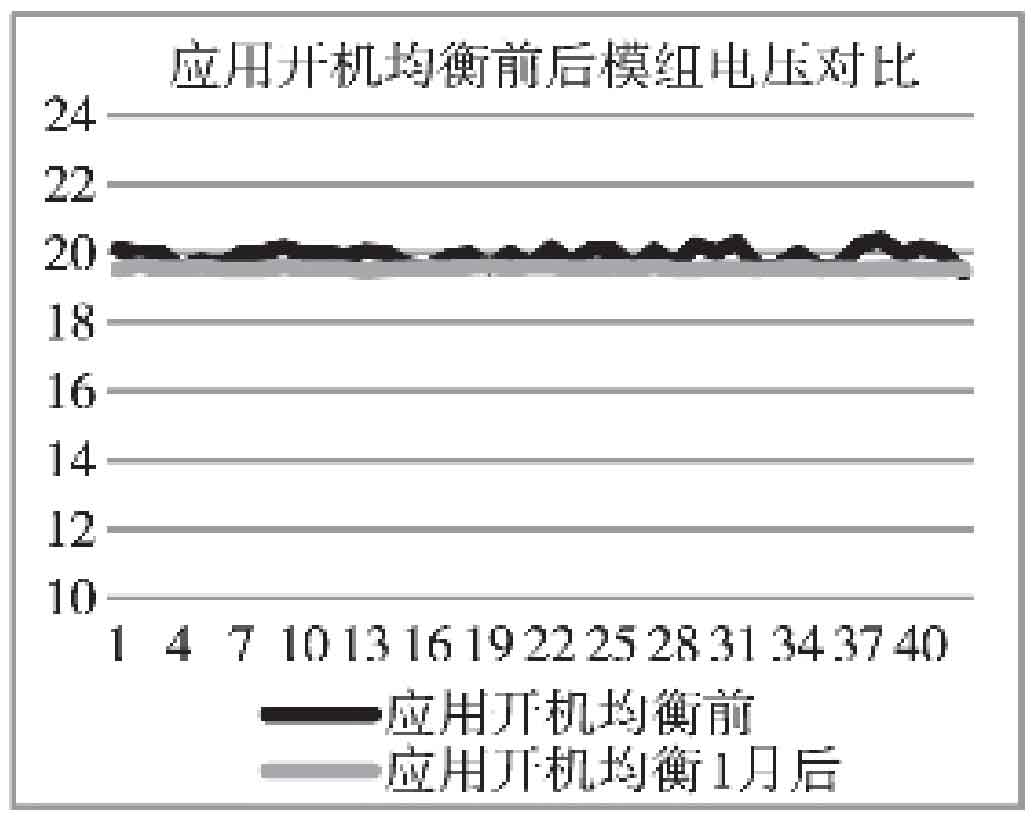
Select the first energy storage power supply of HMU as the test object. Before applying power balancing, obtain the module voltage through the upper computer and record it. Then, add power balancing function to the main control unit and voltage balancing unit. After one month of vehicle testing, the module voltage was obtained again through the upper computer and recorded. The data statistical analysis is shown in the figure and table.
| Maximum module voltage/V | Minimum module voltage/V | Maximum pressure difference/V | |
| Before applying power on balance | 20.389 | 19.456 | 0.933 |
| After one month of application startup balancing | 19.646 | 19.48 | 0.166 |
As can be seen from the figure and table, the maximum pressure difference between modules of the energy storage power supply has decreased from 0.933 V to 0.166 V after applying power on balance, and the effect is significant.
5. Conclusion
A voltage balancing method for system startup has been designed – startup balancing. From the above discussion, it can be seen that startup balancing is a power consuming balancing method that achieves consistent voltage levels by consuming high voltage module energy, compensating for the shortcomings of voltage balancing within the module.
In the actual application process, the designed startup balancing strategy method is effective and feasible, and has been applied well in projects. In the research and development design of other projects, appropriate balancing time can be set according to the different parameters of the supercapacitor unit and balancing unit components selected for specific projects; Set the number of modules involved in power on balancing based on the system’s module configuration and actual needs.