
The proliferation of cell energy storage system deployments is a cornerstone of the global transition towards a sustainable energy infrastructure. These systems are indispensable for grid stability, renewable energy integration, and peak shaving. However, this rapid expansion is shadowed by significant safety concerns, highlighted by several high-profile fire incidents at energy storage facilities worldwide. The inherent fire risk within densely packed battery modules necessitates a paradigm shift from passive to active, intelligent safety management. This paper delves into an integrated, automatic fire detection and suppression framework specifically engineered for cell energy storage system prefabricated cabinets. We examine the foundational science, evaluate critical technologies, and propose a robust, multi-layered protection strategy to ensure the safe and reliable operation of these vital assets.
The core of the fire hazard in a cell energy storage system lies in the thermal runaway phenomenon of lithium-ion batteries. This is a self-perpetuating chain reaction where heat generation outpaces dissipation, leading to catastrophic failure. The process is initiated by various abuse conditions—electrical, thermal, or mechanical—and proceeds through a series of exothermic chemical reactions. Understanding this sequence is paramount for designing effective early warning systems.
- SEI Decomposition: The Solid Electrolyte Interphase (SEI), a metastable layer on the anode, begins to decompose at temperatures around 60-90°C, releasing flammable gases.
$$ \text{SEI (various components)} \xrightarrow{\Delta} \text{Gases (e.g., C}_2\text{H}_4) + \text{Heat} $$ - Anode-Electrolyte Reaction: With the protective SEI layer compromised, the lithiated anode (e.g., graphite-LixC6) reacts exothermically with the organic electrolyte.
$$ \text{Li}_x\text{C}_6 + \text{Electrolyte (EC, DMC, etc.)} \rightarrow \text{Li}_2\text{CO}_3 + \text{Gases (C}_2\text{H}_4, \text{C}_2\text{H}_6) + \text{Heat} $$ - Electrolyte Decomposition & Cathode Reactions: At higher temperatures (~130°C and above), the separator melts, leading to internal short circuits. The cathode material (e.g., LFP, NMC) can release oxygen, which further fuels reactions with the electrolyte.
$$ \text{LiFePO}_4 \xrightarrow{\Delta} \text{Fe}_2\text{P}_2\text{O}_7 + \text{Li}_3\text{PO}_4 + \text{O}_2 \quad \text{(for LFP)} $$
$$ \text{Electrolyte (LiPF}_6, \text{ Carbonates)} \xrightarrow{\Delta} \text{PF}_5, \text{ HF}, \text{ CO}, \text{ CO}_2 + \text{Heat} $$ - Combustion of Ejected Gases: The massive gas generation increases internal pressure until the cell vents. These hot, flammable gases (primarily H2, CO, and various hydrocarbons) can ignite upon contact with air, leading to jet fires and propagation to adjacent cells.
$$ 2\text{H}_2 + \text{O}_2 \rightarrow 2\text{H}_2\text{O} + \text{Heat} $$
$$ 2\text{CO} + \text{O}_2 \rightarrow 2\text{CO}_2 + \text{Heat} $$
This cascade produces distinct signatures—temperature rise, specific gas emissions, smoke, and pressure changes—which form the basis for detection.
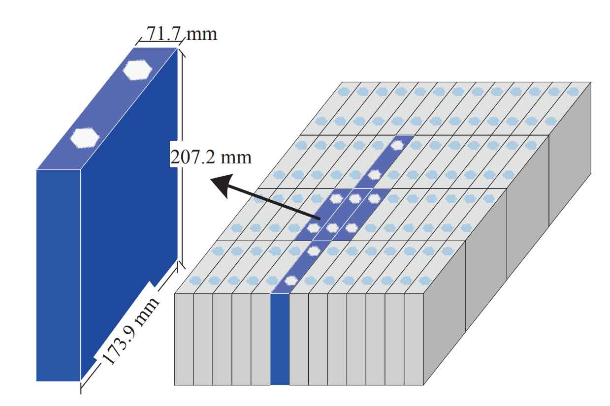
A modern cell energy storage system cabinet demands a multi-parameter, tiered detection approach. Reliance on a single sensor type is insufficient due to the complex and sometimes variable nature of thermal runaway. The following table summarizes the primary detection methodologies.
| Detection Technology | Primary Sensor Type | Measurand / Principle | Advantages | Limitations | Typical Alarm Threshold (Tier 1) |
|---|---|---|---|---|---|
| Gas Detection | Electrochemical, Semiconductor, Laser | Concentration of H2, CO, VOC, HF | Earliest warning; specific to battery failure; can locate failing module. | Sensor drift, poisoning, calibration needs; gas dispersion delays. | H2: 100-200 ppm; CO: 30-50 ppm |
| Thermal Detection | Thermocouple, Fiber Bragg Grating (FBG), IR Camera | Temperature (Point, Distributed, Imaging) | Direct, reliable; good for confirmation and location. | Relatively late signal; thermal inertia delays response. | Rapid Temp Rise > 1°C/s or Temp > 60°C |
| Aerosol/Smoke Detection | Photoelectric, Laser Scattering | Particle density (nm to µm range) | Detects venting and open fire; well-established technology. | Prone to false alarms from dust; late stage in runaway. | Obscuration > 0.5-3.0 %/m |
| Battery Management System (BMS) | Voltage, Current Sensors | Voltage drop, Internal Resistance, Capacity Fade | Very early indication of micro-shorts; integrated into system. | Cannot distinguish between electrical fault and imminent thermal runaway conclusively. | Voltage Delta > 50 mV within module; Sudden Self-Discharge |
The optimal strategy for a cell energy storage system involves a Composite Detection Architecture. This integrates signals from gas, thermal, and aerosol sensors, often fused with BMS data using algorithms (e.g., Bayesian networks, machine learning classifiers). The logic can be represented as a decision function:
$$ \text{Alarm State} = f(S_{gas}(t), S_{temp}(t), S_{smoke}(t), S_{BMS}(t), t) $$
Where a combination of weighted inputs exceeding a defined threshold triggers an alarm. For instance, a low-level H2 detection combined with a localized temperature anomaly provides a much higher confidence warning than any single parameter.
Once a confirmed or high-probability thermal runaway event is detected, immediate and effective suppression is critical. The fire within a cell energy storage system is a Class C (electrical) fire that evolves into a deep-seated chemical fire with prolific flammable gas production. Suppression goals are: 1) Extinguish open flames, 2) Cool adjacent cells to prevent propagation, and 3) Inert the atmosphere to prevent gas ignition. The following table compares主流灭火 agents.
| Suppressant | Mechanism of Action | Key Advantages | Key Disadvantages | Design Concentration for Li-ion Fires |
|---|---|---|---|---|
| Water (Fine Mist) | Cooling (High Latent Heat), Oxygen Dilution, Inerting (Steam), Washing away of vapors. | Excellent cooling; readily available; low cost; non-toxic. | Electrical conductivity (mitigated by mist); water damage; requires large storage/drainage. | Not concentration-based. Flow rate: ~0.5-1.0 L/min per m³ of cabinet volume. |
| Synthetic/Gaseous (e.g., C6F12O – FK-5-1-12) | Chemical Inhibition (Radical Scavenging), Physical Cooling (Vaporization). | Clean, non-conductive, no residue; fast deployment; effective on gas phase fires. | Poor cooling of cells; risk of re-ignition; high cost per kg; potential for toxic HF generation. | Typically 6-8% by volume for inerting. |
| Inert Gases (N2, Ar, CO2) | Oxygen Dilution (Asphyxiation). | Clean, non-conductive; CO2 provides some cooling. | Poor cooling; requires airtight enclosure; high pressure storage; CO2 is a life safety hazard. | N2: >34% O2 reduction; CO2: 34-72% concentration. |
| Hybrid (Gas + Water Mist) | Combined: Gas for rapid flame knockdown/Inerting, Water for sustained cooling. | Synergistic effect; addresses weaknesses of individual agents; high efficiency. | System complexity; higher initial cost. | Dual design based on both agent requirements. |
The design quantity for a gaseous agent like C6F12O for a cabinet is calculated as per ISO 14520 standards. The required mass \( W \) is:
$$ W = \frac{C}{1 – C} \times \frac{V}{S} \times K_{alt} $$
Where:
- \( C \) = Design concentration (e.g., 0.08 for 8%)
- \( V \) = Net volume of the protected cabinet (m³)
- \( S \) = Specific vapor volume (m³/kg) at the minimum expected temperature \( T \) (°C), given by:
$$ S = k_1 + k_2 \times T $$
With \( k_1 = 0.0664 \) and \( k_2 = 0.000274 \) for FK-5-1-12. - \( K_{alt} \) = Altitude correction factor.
For a 30 m³ cabinet at 15°C, using 8% concentration:
$$ S = 0.0664 + 0.000274 \times 15 = 0.07051 \, \text{m}^3/\text{kg} $$
$$ W = \frac{0.08}{1 – 0.08} \times \frac{30}{0.07051} \approx 37.0 \, \text{kg} $$
The true efficacy of a safety system for a cell energy storage system lies in the seamless integration and intelligent control of detection and suppression—the Automatic Detection and Suppression System (ADSS).
System Architecture & Logic: The ADSS is a dedicated safety controller independent of, but communicating with, the main cell energy storage system BMS. It receives real-time inputs from all cabinet sensors. A tiered alarm logic is implemented:
- Pre-Alarm (Tier 1): Triggered by a single early indicator (e.g., BMS anomaly, slight H2 increase >100 ppm). Action: Alert operators, increase ventilation (if safe), prepare suppression system.
- Confirmed Alarm (Tier 2): Triggered by a second corroborating signal (e.g., H2 >200 ppm AND local temperature rise >2°C/s). Action: Initiate pre-discharge sequence for suppression, send critical alert, begin safety shutdown of affected cabinet’s power.
- Fire Alarm (Tier 3): Triggered by open flame indicators (smoke, rapid temperature spike >150°C). Action: Immediate full discharge of suppression agent into the cabinet.
This multi-tier approach minimizes false discharges while ensuring rapid response to real events.
Suppression Delivery Strategy: For maximum effectiveness, a two-stage or zoned delivery is often used in a cell energy storage system cabinet.
- Module-Level or Targeted Delivery: Upon a Tier 2 alarm, a small quantity of agent (e.g., C6F12O) is directed specifically at the suspected failing module or cluster to attempt early containment.
- Flooding of Entire Cabinet Volume: Upon Tier 3 alarm or if Tier 2 suppression fails, the main system floods the entire cabinet volume with the primary suppressant (e.g., water mist or a larger quantity of gas) to fully inert the atmosphere and cool all cells.
The sequencing in a hybrid system is crucial: the gaseous agent is deployed first for rapid inerting and flame knockdown, followed within seconds by the water mist system for sustained cooling over a longer period (e.g., 30-60 minutes) to prevent thermal propagation.
The evolution of the cell energy storage system demands continuous advancement in safety technology. Future directions include:
- Advanced Prognostics: Integrating electrochemical impedance spectroscopy (EIS) and advanced BMS algorithms to predict cell failure days or weeks in advance, moving from detection to prediction.
- Smart Suppressants: Development of “intelligent” mist additives that enhance cooling, form protective films, or neutralize toxic gases like HF.
- Digital Twin for Safety: Creating a real-time virtual model of the cell energy storage system cabinet that simulates thermal and gas dispersion dynamics during an event, optimizing ADSS response in real-time.
- Standardization & Certification: Developing more rigorous, internationally harmonized testing standards (e.g., UL 9540A, IEC 62933-5-2) specifically for integrated ADSS performance in full-scale cell energy storage system units.
In conclusion, safeguarding cell energy storage system prefabricated cabinets is a multi-disciplinary challenge requiring a defense-in-depth strategy. There is no single “silver bullet.” Security is achieved through a layered approach: understanding the fundamental electro-thermal-chemical failure modes, deploying a composite network of sensors for earliest possible warning, selecting and properly designing suppression agents that address both flame and thermal propagation, and, most critically, integrating these components via an intelligent, reliable, and fast-acting control system. The proposed framework of a multi-tiered, composite detection system coupled with a hybrid or optimally sequenced suppression strategy represents a robust solution. As the scale and ubiquity of cell energy storage system installations grow, continued investment in and refinement of these automatic fire safety technologies are not just an engineering priority but a fundamental requirement for the sustainable and trusted growth of the global energy storage industry.