
With the increasingly prominent energy and environmental issues, solar energy is rapidly developing as a clean and renewable energy source, and solar power generation facilities are increasing rapidly, among which solar inverters are essential. Ansemy Semiconductor’s Power Integrated Module (PIM) solution provides high energy efficiency and reliability in the design of solar inverters.
1. Architecture of solar inverters, uninterruptible power supplies (UPS), and energy storage systems (ESS)
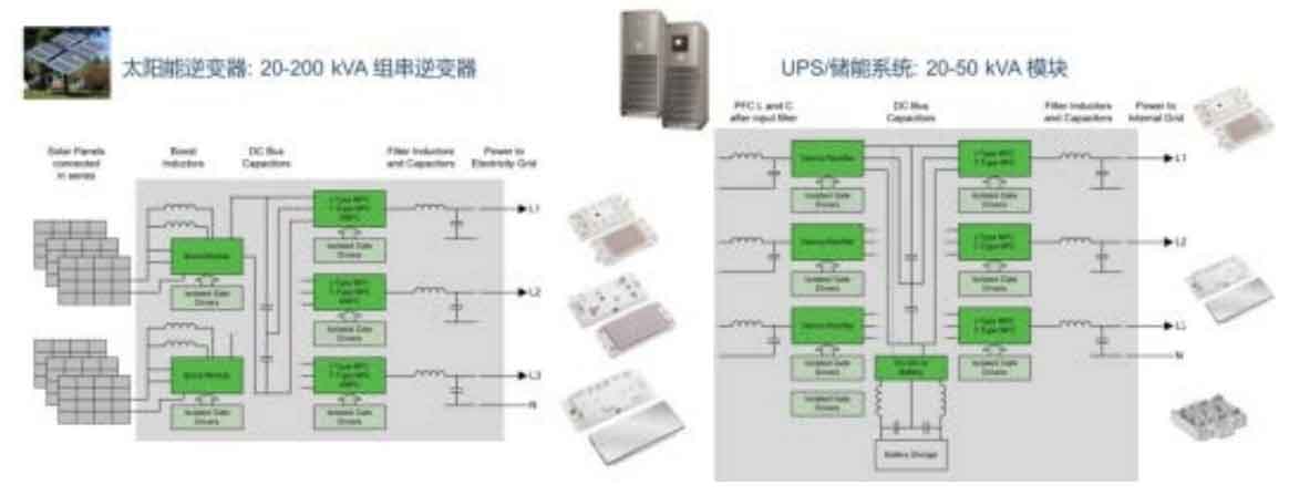
In battery powered operation, uninterruptible power supplies, energy storage systems, and solar inverters are composed of DC-DC converters and DC-AC solar inverters, and the solution enjoys a high degree of similarity and universality. As shown in Figure 1, a 20 to 200kVA series solar inverter includes a boost inductor, boost module, DC bus capacitor, solar inverter module, AC filtering inductor, and capacitor, while a 20 to 50kVA uninterruptible power supplies/energy storage systems includes input filtering, power factor correction (PFC), rectifier, DC bus capacitor, solar inverter module, filtering inductor, and capacitor. uninterruptible power supplies can provide backup power in the event of power outages or unstable power supply, and is widely used to power critical components in countless applications such as telecommunications, data centers, and various industrial facilities. energy storage systems is increasingly being deployed in conjunction with renewable energy to ensure uninterrupted power supply and promote modernization of the power grid.
2. Solar inverters/uninterruptible power supplies/energy storage systems solutions and trends
Due to the demand for higher energy efficiency, solar inverter modules generally adopt multi-level structures in typical applications, especially 3-level (NPC or T-NPC) solar inverters are popular because 3-level solar inverters have higher energy efficiency, smaller total harmonic distortion (THD) of current, lower input leakage current, and smaller output filtering, which are closer to the ideal sine wave. Of course, due to the increase in the number of IGBTs, drivers, and auxiliary power sources, the cost of Bill of Materials (BOM) and the complexity of control schemes will also increase. Ansemy Semiconductor provides a PIM solution, which adopts a multi series solar inverter structure without a power frequency transformer, while optimizing the chipset and layout to reduce losses, achieving the overall realization of high-frequency switching, high energy efficiency, and high power density.
3. Typical 3-level solar inverter topology
TNPC, NPC, and ANPC are three typical three-level solar inverter topologies. TNPC achieves low switching loss and NPC has been widely used in the past, while ANPC has the advantage of low parasitic inductance. The three-level scheme provided by Ansemi Semiconductor covers an output power of 20kW to 220kW, and adopts different packages of Q0, Q1, and Q2 for users in different power ranges to choose from. Q0 and Q1 packaging are used for boost modules up to 25kW and 40kW, as well as inverter modules up to 15kW and 20kW, respectively. Q2 packaging with copper substrate enhances heat dissipation, used for 1500V inverter modules up to 220kW and 1100V inverter modules up to 90kW.
4. Selection guide for boost and solar inverter modules and PIMs
For the DC-DC boost module, one MPPT channel can support up to approximately 25A photovoltaic (PV) transmission
In (2 PV boards in parallel), each module has different MPPT numbers, IGBT rated currents, and SiC diode ratings. The appropriate number of modules and modules should be selected based on the required number of MPPTs for the application and the power of each MPPT.
For applications with a maximum DC bus of 1100V, the corresponding 3-level DC-AC solar inverter module needs to be selected based on the required power level of the solar inverter. For smaller power solar inverters, such as 10kVA, Ansemi Semiconductor provides a three in one solution that consolidates three-phase A, B, and C into one Q1 package.
In addition, in response to the rapidly growing demand for 1500V photovoltaic power plants in the near future, Ansemy Semiconductor will also promote
A 1500V three-level solar inverter and boost module are produced. Compared with mainstream 1200V wafers in the market, the 1000V IGBT wafer has a thinner substrate area, resulting in smaller conduction resistance and significantly reduced losses. For single-phase solar inverters, Ansemi Semiconductor will launch modules using the H6.5 topology, which greatly reduces the common mode current compared to the widely used H-bridge topology to meet the safety requirements of grid connection without isolation transformers. Considering the increasing demand for battery energy storage in future household use, bidirectional power flow should be considered when selecting wafers, which can either transmit power to the grid or store power from the grid in the battery. It can operate efficiently when the power factor is 1 or -1.
When choosing a PIM, the first thing to know is the application requirements, such as rated power and voltage, whether a boost module is needed, whether to use 3-phase or single-phase, and what topology to use. Then, together with the application engineer, calculate the required number of modules and use simulation software to calculate losses and maximum junction temperature.
5. Practical design examples
Figure 2 is the circuit diagram of a 60kW solar inverter product. Taking the 1100V three-phase solar inverter as an example, the red block diagram shows one DC boost module, which is used to increase the input voltage of the photovoltaic panel from lower to higher DC bus capacitor voltage. The blue block diagram shows the TNPC three-level inverter module, which realizes energy conversion from DC to AC.
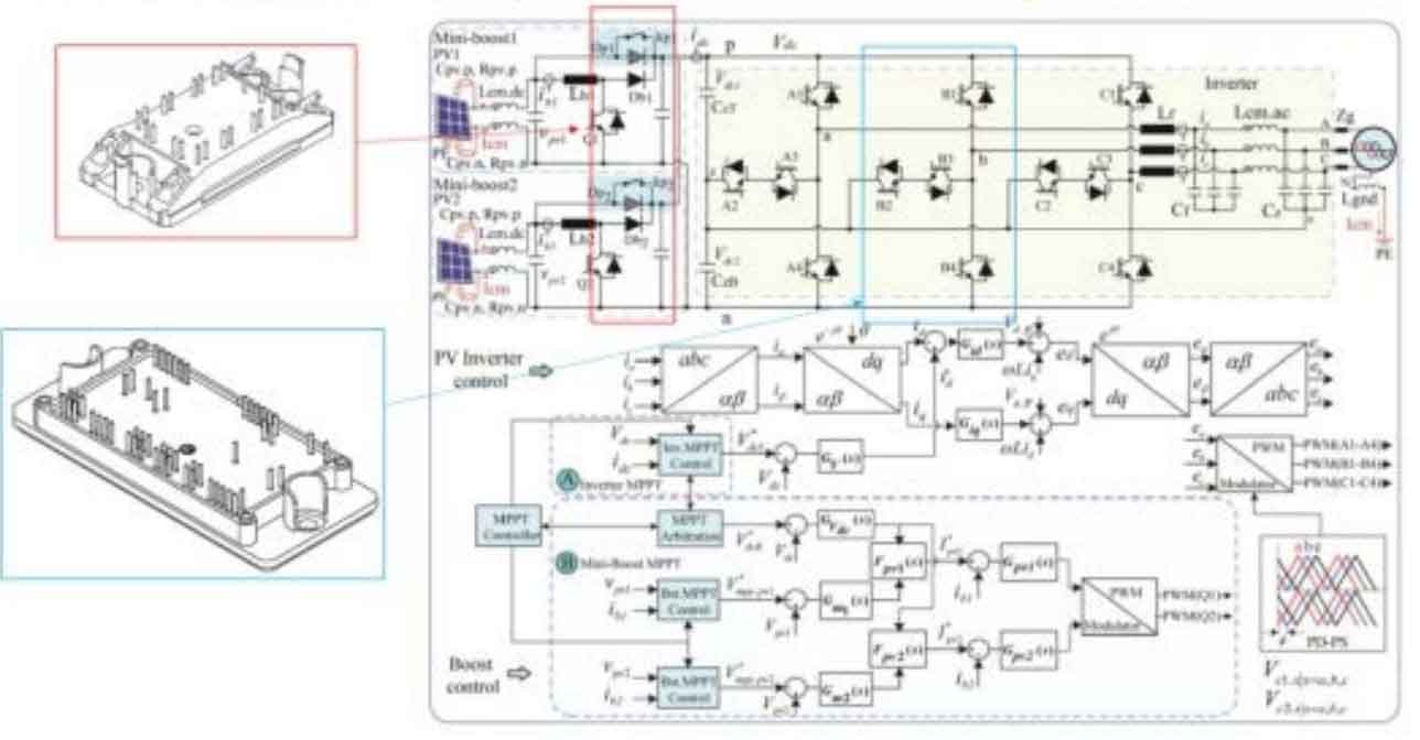
In addition, some passive devices such as electrolytic capacitors, thin film capacitors, common mode inductors, AC filter inductors, DC filter inductors, AC relays, etc. are also used. Electrolytic capacitors support the stability of DC bus voltage, thin film capacitors are used to absorb the peak voltage generated during IGBT switching, and common mode inductors provide high impedance in the common mode circuit, suppressing common mode interference EMI and common mode losses.
To design an 80kW system, assuming 4 Q0 boost modules NXH80B120H2Q0SG and 3 Q2Pack inverters NXH160T120L2Q2F2S1G are selected, the power of each MPPT is 80/8=10kW, the PV current is 10kW/600V=16.67A, and the power of each inverter module is 80/3=26.67kW. Then, input the following system condition parameters through simulation software to calculate energy efficiency and evaluate the junction temperature of IGBT and diode.
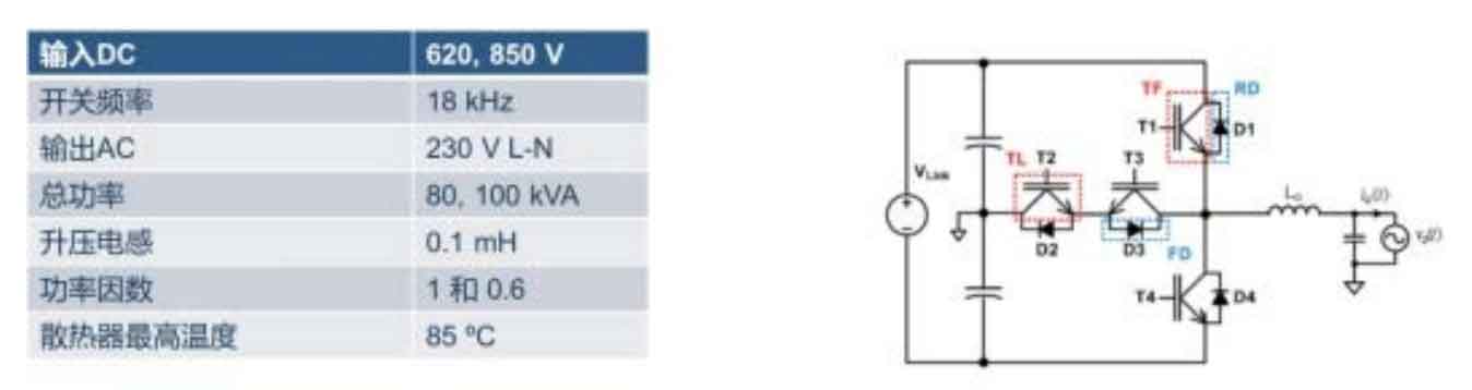
The simulation results show that the system energy efficiency of this design scheme exceeds 98%, and the loss and thermal performance are excellent, so it is feasible.
6. Design considerations for gate drive circuits
The conduction and shutdown of IGBT require charging and discharging the CGE circuit. In the field of photovoltaic applications, control signals and high-voltage circuits need to be isolated. When laying out the board, the gate drive circuit should be placed near the PIM module as much as possible to reduce the stray inductance of the drive circuit, as higher stray inductance may cause gate voltage oscillation. When selecting the gate resistance value Rg, a compromise needs to be made between switch loss and voltage and current stress. In addition, designers need to pay attention to the common mode transient suppression (CMTI) parameters of the isolation chip.
7. Summary
The world is shifting towards renewable energy sources such as solar energy to replace traditional energy sources, in order to address increasingly prominent energy and environmental issues. Ansemy Semiconductor offers a variety of three-level solar inverter modules and boost modules, using optimized power semiconductor devices and packaging designs to provide over 98% energy efficiency and high reliability in solar inverters, uninterruptible power supplies, and energy storage systems. It also offers various gate drivers used in conjunction with power modules to optimize system performance, accompanied by rapid and in-depth technical support, to help customers win business opportunities and expand their business.