
1. Energy storage system model selection
The commonly used heat transfer model for packed bed energy storage systems is the Schumann Model. It is a one-dimensional two-phase heat transfer model based on the assumption of a porous medium model, with the basic assumption that an ideal advection fluid passes through a packed bed. The model consists of two equations that describe the energy conservation of fluids (liquid phase) and solid filling materials (solid phase), respectively.
Among them, the first term on the left side of the formula is the time term of the energy change of the heat transfer fluid and solid particles, and the second term on the left side of the formula is the convection term. On the right side of the equation is the energy source term, which represents the heat transfer between solid particles and fluid, and the heat transfer between fluid and solid particles, respectively. Two equations are coupled by heat transfer coefficients ℎ𝑠\f 𝑎, representing heat exchange between solid particles and fluids through convection. ℎ𝑠 f is the heat transfer coefficient between the filling material and the fluid, and 𝑎 is the shape factor.
The Single Phase Continuous Model is a single expression of heat transfer in a packed bed derived from the interaction between fluid (liquid phase) and solid particles (solid phase). By assuming that the solid and liquid phases are in a thermal equilibrium state, the energy conservation equations of the solid and liquid phases are expressed uniformly, and the effective thermal conductivity is used to consider the thermal conductivity of the thermal storage medium. The equation form is as follows:
Compared to the Schumann model, the single-phase continuous model has smaller computational complexity. However, it cannot accurately calculate the temperature distribution of the solid energy storage system medium and heat transfer fluid in the packed bed, so its application is relatively limited. The Schumann model is only applicable to domains with large Reynolds numbers, however, for domains with small Reynolds numbers, the equation should include terms related to axial heat conduction of the solid phase.
The Two Phase Continuous Model considers both the thermal non-equilibrium between the heat transfer fluid and the solid medium, as well as the axial heat conduction. The thermal conductivity of the solid and liquid phases should be evaluated based on the cross-sectional area of the packed bed, and the control equation for energy conservation is as follows:
When the wall effect has a significant impact on the tank body, it can lead to uneven flow through the wall and heat loss. Therefore, using a two-phase continuous model is appropriate. Meier et al. provided a lower limit for a reference index, which states that when the ratio of tank diameter to solid particle diameter is greater than or equal to 40, the non-uniformity of fluid flow near the wall can be ignored. The two-phase continuous model is more accurate in predicting the temperature distribution of fluids and solid media in the tank, but it also takes longer to calculate.
The Dispersed Concentrated Model is a more accurate method for evaluating the thermal behavior of packed bed energy storage systems. This model assumes that the fluid flows in a dispersed advection state and that the temperature distribution inside the particles is radially symmetric. By calculating the internal temperature of solid particles at different positions, the temperature distribution of the entire packed bed is reflected, and the energy source term of the heat transfer fluid energy conservation equation is calculated using the surface temperature of solid particles. The form of this heat transfer model is as follows:
At the boundary 𝑟=𝑅, the temperature distribution of solid particles is solved using the following boundary conditions, expressed as:
Compared to the above models, the mixed diffusion model can more accurately reflect the transient heat transfer behavior during the heat storage process of a packed bed energy storage system. However, due to the need to separately calculate the internal temperature distribution of the heat transfer fluid and solid particles at different positions, this model requires a large amount of computation. Because the non thermal equilibrium between fluid and solid particles is considered, the mixed diffusion model can obtain more accurate results when describing the transient heat transfer problem of phase change packed bed heat storage and release.
The porosity of the packed bed is greatly influenced by the particle distribution, which also determines the energy storage and pressure drop of the packed bed. For the influence of multi-scale solid particle arrangement and thermal analysis, a new energy equation needs to be coupled. Beasley and Clark proposed a three-phase model that considers axial and radial diffusion of temperature and temperature distribution on the wall.
Liquid phase:
Solid phase:
Wall:
Unlike the above computational models, Hoffmann et al. designed a one-dimensional transient model using three coupled equations, namely solid heat transfer, fluid heat transfer, and a thermal gradient model considering tank wall effects.
Liquid phase:
Solid phase:
Wall:
Compared to the above two models, the formula takes into account the radial diffusion of temperature in the liquid phase, so the formula has an additional radial heat conduction term. However, the model proposed by Beasley and Clark did not consider the heat loss in contact between the solid phase and the tank wall, so there is no final term in the formula. The model proposed by Hoffmann et al. includes diffusion terms and wall heat loss, which can be considered as an extension of the two-phase continuous model.
Odenthal et al. proposed a three equation model for packed beds with different particle size arrangements. The packed bed achieves higher packing density through the combination of large and small particles, namely double dispersed fillers. Based on the Schumann model, in addition to the fluid differential equation, two differential equations are also established for large and small solid particles.
The above is a summary of the models used for modeling the unit of the packed bed energy storage system. Based on the above analysis, taking into account both computational accuracy and computational complexity, this paper starts with a two-phase continuous model and establishes a local non thermal equilibrium mathematical model for porous media to model the units of the packed bed energy storage system.
2. Model assumptions
Based on the analysis of the selection of heat storage models mentioned above, a two-phase continuous model and local non thermal equilibrium theory were used to simulate the units of the phase-change packed bed energy storage system. The dynamic characteristics of the energy storage system and the flow and heat transfer behavior of molten salt in the tank were analyzed.
In order to optimize computational efficiency, the following assumptions are made for the model of the packed bed energy storage system:
(1) The solid particles in the packed bed tank are considered as homogeneous and isotropic porous media, and the fluid flow inside is considered as advection flow, with the fluid flow friction ignored;
(2) Neglecting the flow velocity and temperature gradient of the fluid along the radial direction, only considering the axial velocity and temperature changes;
(3) Due to the small thickness and specific heat of the packaging material, the thermal resistance of the packaging material is ignored;
(4) The phase change material is uniformly filled in the encapsulated sphere, without considering the volume changes that occur during the solid-liquid phase transition process;
(5) Not considering the natural convection effect of phase change materials in encapsulated spheres;
(6) The radiation heat transfer between molten salts is ignored, and there is no internal heat generated in the packed bed.
3. Model validation
To verify the applicability of the phase change packed bed energy storage system, experimental data from Nallusamy et al. were selected for comparison. The schematic diagram of the on-site experiment device is shown in Figure 1, which includes a small cylindrical phase change packed bed hot water energy storage system unit, and the tank body is filled with encapsulated phase change spherical materials. The system uses solar collectors to heat cold water, and a splitter is installed at the top of the tank to ensure even water flow. Due to the fact that the system only has one circulating water pump, only one process of heat storage and release can be carried out simultaneously each time.
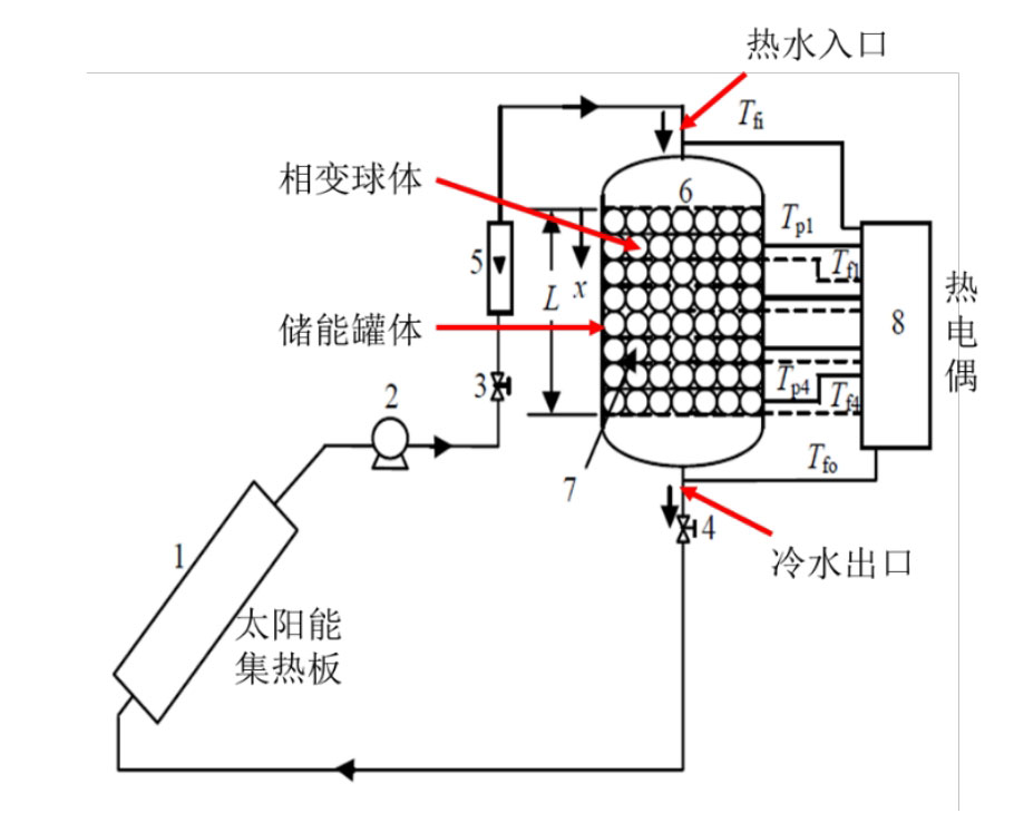
The thermal properties of the phase change materials used in this system are shown in the table. The experiment used a tank with a diameter of 360mm and a height of 460mm. The stainless steel tank had a capacity of 47 liters and was insulated externally with 50mm thick glass rock wool. Paraffin wax with a phase change temperature of 60 ℃ is used as the energy storage system medium, encapsulated in capsules. The diameter of the sphere is 55mm, and water is used as the heat transfer fluid (HTF). The porosity of the packed bed is 0.5. The initial and boundary conditions of the system are: during the heat storage process, the initial temperature of the system is 32 ℃, the inlet temperature of the water flow is 70 ℃, and the fluid flow rate is 2L/min. Except for the inlet and outlet, the outer surface of the system is made of insulation materials, and the heat storage time is 160 minutes. Taking the temperature changes of phase change materials at three axial positions (x/H=0.25), (x/H=0.5), and (x/H=1) of the tank as an example, the simulation results are compared, as shown in Figure 2.
| Parameters | Size |
| Melting point of phase change materials (℃) | 60 |
| Phase change latent heat (kJ/kg) | 213 |
| Phase change material density (kg/m ^ 3) | 861 (solid phase)/778 (liquid phase) |
| Specific heat of phase change materials (J/kg · K) | 1850 (solid phase)/2384 (liquid phase) |
| Thermal conductivity of phase change materials (W/m · K) | 0.4 (solid phase)/0.15 (liquid phase) |
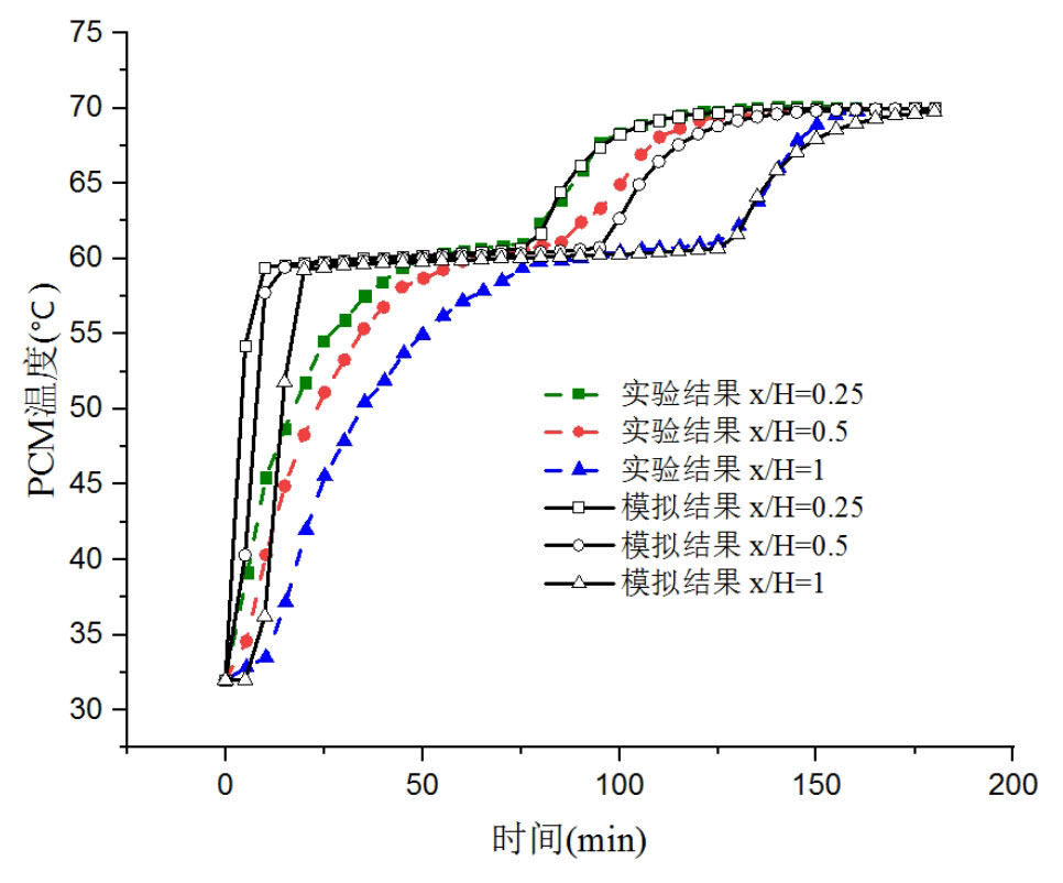
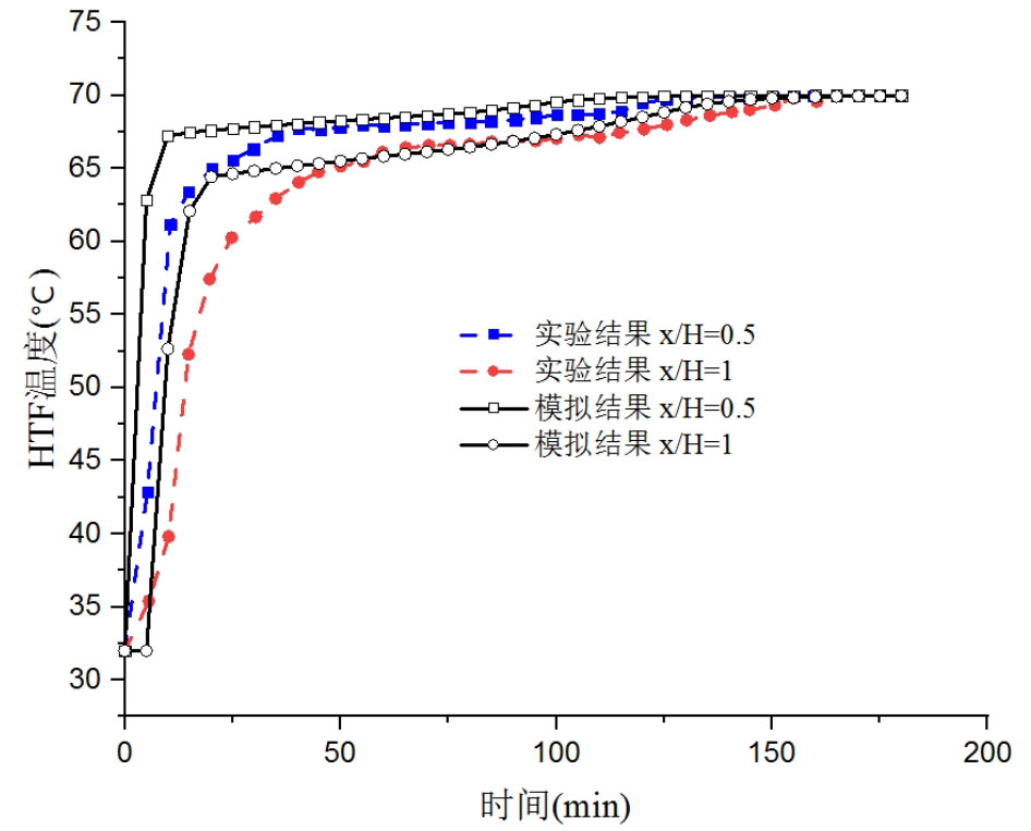
From Figure 2, it can be seen that the temperature change of phase change materials can be divided into three stages. The first stage is the solid-state heat storage stage, where the heat storage process begins and the solid phase change material rapidly heats up. The second stage is the phase change heat storage stage. When the phase change material reaches the melting temperature, it changes from solid to liquid. As the heat storage time increases, the temperature of the phase change material remains basically unchanged. The third stage is the liquid thermal storage stage, where the phase change process is completed and all the phase change materials become liquid. Over time, they reach the fluid inlet temperature. The simulation results can clearly display these three stages, and the temperature change curve of the phase change material in the simulation results is consistent with the experimental results as a whole. The difference between simulation results and experimental results is mainly in the initial stage of the heat storage process, but the maximum error between experimental and simulated heat storage time is 7.1%, which is within a reasonable and acceptable range. Figure 3 shows the temperature variation of the heat transfer fluid at different positions in the tank over time. The simulation results and experimental results also show relatively high similarity, and the error between the two mainly occurs in the initial stage of the heat storage process. In the first 50 minutes, the maximum error between the two is 10.8%.
Due to the uncontrollability of experimental environment conditions, uncertainty of experimental testing, and simplification of the model, there are some differences between the numerical simulation results and experimental results, but the differences are all within the range of 15%. Overall, there is good consistency between the experimental and simulation results, so the validated numerical model is accurate and reliable. Through the verification of the above model, it can be concluded that the model has high applicability for simulating packed bed thermal storage systems.
Based on the different energy storage methods and working principles of energy storage systems, this chapter introduces the structural characteristics of concrete energy storage systems and phase change packed bed energy storage systems. A three-dimensional physical model was established for the concrete sensible heat energy storage system. Based on the physical process of the interaction between the heat transfer fluid and the energy storage medium, the control equation for the heat transfer process was determined, providing a basis for solving the temperature field. The reliability of the model was verified by comparing it with experimental data from previous scholars. For the packed bed energy storage system, a comparative analysis was conducted on the modeling methods of different packed bed energy storage systems. Based on the accuracy and computational efficiency of the simulation, a two-phase continuous model and local non thermal equilibrium theory were selected to simulate the transient heat transfer process of the packed bed energy storage system. The results calculated using this model were compared with the experimental results of previous scholars, verifying the effectiveness of the model. The above work provides a theoretical basis for further research on the thermal storage performance of concrete energy storage systems and single tank filled bed energy storage systems.