
The power supply system includes two parts: the power supply system and the transmission and distribution system, which can directly distribute the supply energy generated by the core power grid to other subordinate electrical equipment. The conventional power supply system is basically divided into three connection forms: TT, IT, TN, etc. Among them, TN system can be divided into three characteristic manifestations: TN-S, TN-C, TN-C-S, etc. The power grid, as the backend support structure of the power supply system, consists of substations, power sources, load centers, and transmission and distribution lines. Normally, there is always an absolutely stable regulating connection relationship between each power supply point, which can promote the exchange voltage between high and low voltage power grid structures to quickly balance, and on the other hand, improve the economy and safety of the entire power supply network. In order to ensure the quality of power transmission at the high-voltage end, while improving the utilization rate of participating equipment in the power supply system, adjust the load curve related to the energy storage power supply, so as to rationalize the application of power resources and achieve the goal of controlling the total output consumption of the power network.
Based on the long-term operation of the power grid, the sensitivity of the entire power supply system to distribution transformation gradually decreases, leading to a significant differential change in the RF filtering output power of related participating equipment. To avoid the occurrence of the above situation, an inverse F-class output harmonic impedance method is proposed to determine the specific numerical level of energy storage level by judging the electromagnetic and capacity mode in the soft switching DC/DC converter circuit. However, this method requires a long adjustment time for the grid’s RF filtering, which cannot achieve the ideal output power of the RF wave per unit time. To solve this problem, this article designs a harmonic control method for the high-power converter of the energy storage power supply system in the power grid. Under the action of multiple components such as the power topology circuit and compatible relays, the specific high-power fundamental parameters are calculated. Based on the actual impedance control conditions, the application execution status of the harmonic converter sub circuit is adjusted to solve the problem of poor sensitivity to distribution transformation in the power supply system.
1.Energy storage environment of power supply system in the power grid
The power storage system of the power grid power supply system consists of three types of components: high-power switching power supply circuit, energy storage type power transformer, and grid compatible relay. The specific construction method is as follows.
1.1 High power switching power supply circuit
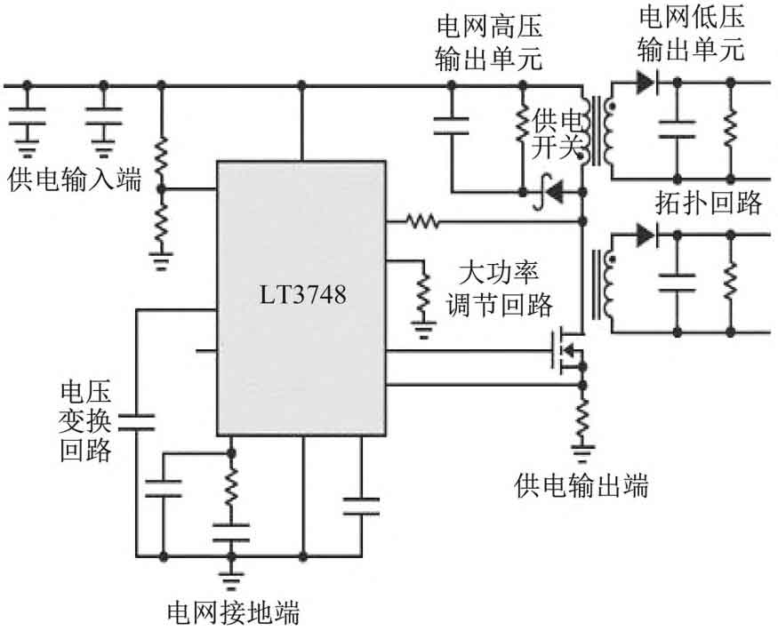
The high-power switching power supply circuit of the power grid power supply system consists of a voltage conversion circuit, a regulation circuit, and a topology circuit. The power supply input terminal is directly connected to the voltage conversion circuit. After the harmonic electrons enter the LT3748 converter host, the grounding terminal of the power grid will quickly change from a closed state to a connected state, which can transmit the incompletely consumed electrons to other lower level application components while receiving the power supply control voltage. The high-power regulation circuit is located in the middle of the topology circuit of the switching power supply, connecting the voltage conversion circuit at both ends of the power supply system and the topology circuit. When the power supply switch is in a facultative connection state, the high-voltage output unit of the power grid can quickly discharge the temporary DC electrons in the components, and the low-voltage output unit of the power grid can obtain a portion of the transmission current based on the actual resistance load in the topology circuit. The topology circuit occupies a relatively small volume in high-power switching power supply circuits, responsible for integrating scattered DC electrons into a bundle transmission form for the retrieval and utilization of harmonic control components such as energy storage power transformers and grid compatible relays. The specific circuit is shown in Figure 1.
1.2 Energy storage power transformer
The energy storage power transformer is a direct subordinate execution structure of a high-power switching power supply circuit, consisting of four parts: an external metal shell, input wires, output wires, and harmonic control interface slots. Normally, the rated power of the power transformer does not exceed 20 W, the safe operating voltage does not exceed 380V, and the frequency of the power supply and energy storage cycle is always maintained at 50-60Hz. The input wire is connected to the power supply output terminal of the high-power switching power supply circuit, and can directly withstand the 220V harmonic voltage from the low-voltage output unit of the power grid. After the internal conversion resistor spontaneous conversion operation, it becomes a DC transmission voltage that can be directly stored by the power supply system. Due to the connection between the output wire and the top-level interface of the grid compatible relay, in order to achieve stable output of grid harmonic voltage, the physical numerical value of this component is at least “3”. Two blue wires are responsible for transmitting AC voltage, and one black wire is responsible for transmitting DC voltage. The harmonic control interface slot is attached to both the front and back directions of the metal shell at the same time, accommodating the output wire and input wire respectively. During the given harmonic control cycle, the two always maintain the same transformation effect on the transmission electron. The structure of the energy storage power transformer is shown in Figure 2.
1.3 Grid compatible relays
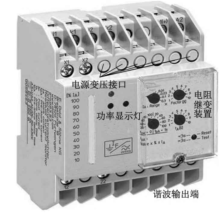
The grid compatible relay is the core processing component of harmonic control instructions for high-power converters in the power supply system, consisting of display lights, transformer interfaces, resistance relay devices, and other components. The power transformer interface serves as the connection path between the grid compatible relay and the energy storage type power transformer, responsible for coordinating the wavelength of harmonic electronic transmission, and changing the current and voltage difference drop values in the sub circuits according to the application requirements of the power topology circuit. The resistance relay device is the core harmonic induction component in the power grid compatible relay. Based on the specific real value of the voltage distribution at both ends of the unit organization, the resistance value loaded on the device body is changed to achieve stable RF wave output power of the high-power converter in the energy storage power supply system. The power display light is directly connected to the harmonic output terminal. When the load voltage of the grid compatible relay is higher than the ideal value level, both red lights light up simultaneously, and the harmonic electronic value at the output terminal gradually increases; When the load voltage of the grid compatible relay is lower than the ideal value level, both red lights go out at the same time, and the green light comes on, gradually reducing the harmonic electronic value at the output end. The structure of the grid compatible relay is shown in Figure 3.
2.Harmonic control method for high-power converters of energy storage power sources
Under the support of the energy storage environment of the power grid power supply system, the design of the harmonic control method for the high-power converter of the energy storage power supply is completed based on the construction of harmonic transformation sub circuits, calculation of high-power fundamental wave parameters, and determination of impedance control conditions.
2.1 Harmonic converter sub circuit
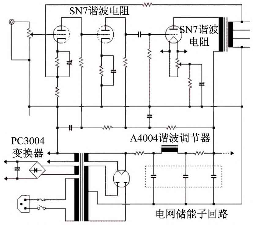
The harmonic converter sub circuit is a lower level executive control component of the high-power switching power supply circuit, with the power grid energy storage sub circuit as the core component. The A4004 harmonic regulator is located at the top of the power grid energy storage sub circuit, and is connected to two SN7 harmonic resistors with different resistance values at the left and right ends. Among them, the SN7 harmonic resistor at the left end is responsible for carrying the electronic quantity transmitted from the grid compatible relay, and can directly adjust the energy storage power value in the power supply system within the established control cycle; The SN7 harmonic resistor at the right end is connected to the energy storage power transformer, and the high-power RF wave value of the converter equipment load is adjusted based on the actual value level of the input resistor. The PC3004 converter is located at the leftmost end of the harmonic converter sub circuit and is connected to the grid energy storage sub circuit and SN7 harmonic resistor in the horizontal and vertical directions, respectively. When the harmonic output level changes in high-power switching power supply circuits, this component can quickly convert between closed and connected states, achieving the goal of shortening the control application cycle that matches harmonic electronics. The harmonic converter sub circuit is shown in Figure 4.
2.2 Calculation of high-power fundamental wave parameters
The high-power fundamental wave parameters limit the control authority of the energy storage power supply for harmonic electrons in the power grid power supply system, and are affected by the transmission topology resistance value and the extreme value of radio frequency waves within a given output cycle. The transmission topology resistance value can be expressed as R, which is the average value level of three physical quantities: SN7 harmonic resistance, grid high voltage resistance, and grid low voltage resistance. Normally, as the output time of the power supply system increases, the actual calculation application of this indicator will gradually increase, and it will never exceed the average load real value matched with the energy storage sub circuit in the harmonic transformation sub circuit. The radio frequency wave extreme value has two numerical control parameters: the upper limit index w1 and the lower limit index w0. Compared with other harmonic transformation coefficients, this physical index has stronger application stability, but the maximum and minimum values have opposite effects on high-power fundamental wave parameters. Combining the above physical quantities, the actual calculation results of high-power fundamental wave parameters can be expressed as:
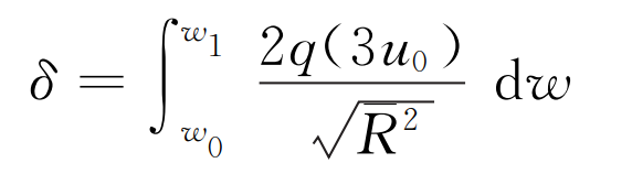
In the formula, q represents the harmonic transmission electron quantity matched with the power supply system power converter, and u0 represents the RF transmission step value of the harmonic electrons in the converter.
2.3 Determination of impedance control conditions
Impedance control is a relatively stable harmonic conversion state of the converter, which describes the parallel conversion process from the power supply energy storage cycle to another power supply energy storage cycle. It can be used as a supplementary condition for high-power fundamental wave parameters. Throughout the entire harmonic control cycle, the maximum electronic reserve quantity of the power grid power supply system is always constrained. Based on the load changes of the high-power converter, the actual transmission period value of the RF wave is determined. Assuming that within a power supply cycle of the power grid, the maximum value of the harmonic output electronic quantity of the energy storage high-power converter is s1, and as the unit control time t continues to extend, the numerical expression of this physical quantity also remains stable. If f is used as the maximum resistance tolerance condition for the grid compatible relay, and equation (1) is used, the impedance control condition for the harmonics of the high-power converter can be expressed as:
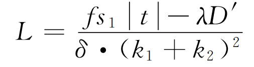
In the equation, λ Represents the high voltage electronic output coefficient carried by the power supply system, D ‘represents the total amount of high voltage electronic output per unit time, and k1 and k2 represent the actual voltage difference of two different converter harmonics.
Complete the calculation of relevant execution coefficients and the construction of equipment components at all levels, and achieve the smooth application of harmonic control methods for high-power converters in the energy storage power supply system of the power grid while the output value of electricity remains stable.
3. Experiments and Analysis
To verify the practical application value of harmonic control methods for high-power converters of energy storage power supply systems in the power grid, the following comparative experiments are designed. Select a power grid execution device with relatively stable output status as the experimental object, use an experimental host equipped with a new harmonic control method as the data recording element of the experimental group, and use an experimental host equipped with an inverse F-class output harmonic impedance method as the control group data recording element. Under the same experimental environment, study the specific changes in the experimental indicators of the experimental group and the control group.
3.1 Establishment of experimental environment
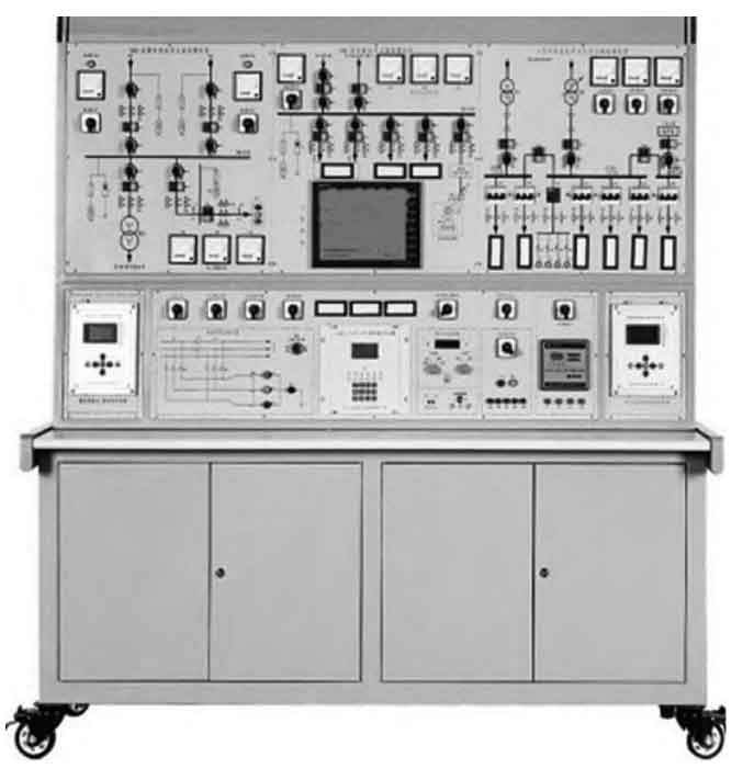
By manually adjusting the model of the experimental host connected to the power grid execution equipment, control other intervention factors to remain unchanged. Based on the specific transformation behavior of the displayed data in the recording host, analyze the trend of changes in the power grid RF filtering adjustment time and RF wave output power. The power grid execution equipment is shown in Figure 5.
3.2 Power grid RF filter adjustment time test
Table 1 shows the specific changes in the RF filtering adjustment time of the experimental group and control group under the established experimental environment.
| Number of experiments/T | Control group/s | Experimental group/s | Ideal value/s |
| 1 | 1.0 | 1.5 | 2.3 |
| 2 | 1.3 | 1.9 | 2.3 |
| 3 | 4.5 | 1.7 | 2.3 |
| 4 | 1.0 | 1.5 | 2.3 |
| 5 | 0.8 | 1.9 | 2.3 |
| 6 | 4.5 | 1.7 | 2.3 |
According to Table 1, the performance of the control group’s power grid RF filter adjustment time is extremely unstable, with a maximum value of up to 4.5 seconds and a minimum value of only 0.8 seconds; The performance value of the experimental group’s power grid RF filter adjustment time is relatively stable, with a maximum value of 1.9 seconds and a difference of 0.4 seconds between the minimum value of 1.5 seconds, which is much lower than the numerical results of the experimental group. In summary, it can be seen that applying the harmonic control method of the high-power converter of the energy storage power supply system in the power grid can minimize the waiting time required for the RF filtering adjustment of the power grid.
3.3 RF Wave Output Power Test
Record the specific changes in the RF wave output power of the experimental group and the control group during the experimental period of 50 minutes. The experimental details are shown in Tables 2 and 3.
| Experimental time/min | RF wave output power/dBm | Average value/dBm | Ideal value/dBm |
| 5 | 38.2 | 39.0 | 27.8 |
| 10 | 38.5 | 27.6 | |
| 15 | 38.8 | 27.9 | |
| 20 | 38.9 | 27.8 | |
| 25 | 39.1 | 27.9 | |
| 30 | 39.1 | 28.1 | |
| 35 | 39.3 | 27.7 | |
| 40 | 39.3 | 27.8 |
Comparing Tables 2 and 3, it can be seen that as the experimental time prolongs, the RF wave output power of the experimental group always maintains a continuously increasing trend, but the increase amplitude in the later stage is significantly lower than in the early stage, with the global maximum reaching 39.4 seconds; The RF wave output power of the control group remained stable first, then continued to decrease, and the global maximum value only reached 23.6 seconds, much lower than the experimental group value. In summary, it can be seen that applying the harmonic control method of the high-power converter of the energy storage power supply system in the power grid can achieve the goal of increasing the output power value of the radio frequency wave.
| Experimental time/min | RF wave output power/dBm | Average value/dBm | Ideal value/dBm |
| 5 | 23.6 | 23.3 | 27.8 |
| 10 | 23.6 | 27.6 | |
| 15 | 23.6 | 27.9 | |
| 20 | 23.5 | 27.8 | |
| 25 | 23.4 | 27.9 | |
| 30 | 23.3 | 28.1 | |
| 35 | 23.2 | 27.7 | |
| 40 | 23.1 | 27.8 | |
| 45 | 22.9 | 27.9 | |
| 50 | 22.7 | 28.0 |
3.4 Output of harmonic control results using different methods
In order to highlight the effectiveness of the proposed harmonic control method for high-power converters in the energy storage power supply system of the power grid, the harmonic control effect of the method proposed in this article is compared with the control group, and the specific results are shown in Figure 6.
According to Figure 6, compared to the initial fluctuation of harmonics, the control group can reduce the amplitude of harmonics to a certain extent. However, during the 50min experiment, the amplitude of harmonics can still reach between -5A and 5A. Compared with the control group, the method proposed in this article can better control harmonics, effectively reduce the output amplitude of harmonics, and enhance the stability of the output current of the converter. The experimental results indicate that the proposed method operates more stably in the power supply system of the power grid.
4. Summary
Compared with the inverse F-class output harmonic impedance method, the harmonic control method combined with the high-power converter of the energy storage power supply system in the power grid can shorten the waiting time for grid RF filtering adjustment while increasing the RF wave output power. According to the analysis of the construction process, this new harmonic control method combines hardware execution devices such as high-power switching power supply circuits and grid compatible relays to ensure the accuracy of the calculation results of high-power fundamental wave parameters, establish stricter impedance control constraints, and achieve the goal of improving the sensitivity of power supply system distribution transformation.