
In recent years, the global push for clean energy has accelerated the adoption of renewable sources like wind and solar power. However, the inherent intermittency and unpredictability of these sources pose significant challenges to grid stability. To address this, energy storage systems have emerged as a critical solution, with electrochemical storage, particularly cell energy storage systems, gaining rapid prominence. Among these, flow battery-based energy storage systems, such as vanadium redox flow batteries, offer scalable and long-duration storage capabilities. In this paper, I explore the harmonic issues arising in such cell energy storage systems, focusing on a large-scale installation, and present a detailed analysis using ETAP software to model, compute, and mitigate harmonic distortions. The goal is to ensure power quality and reliability, which are essential for the efficient operation of modern grids integrated with renewable sources.
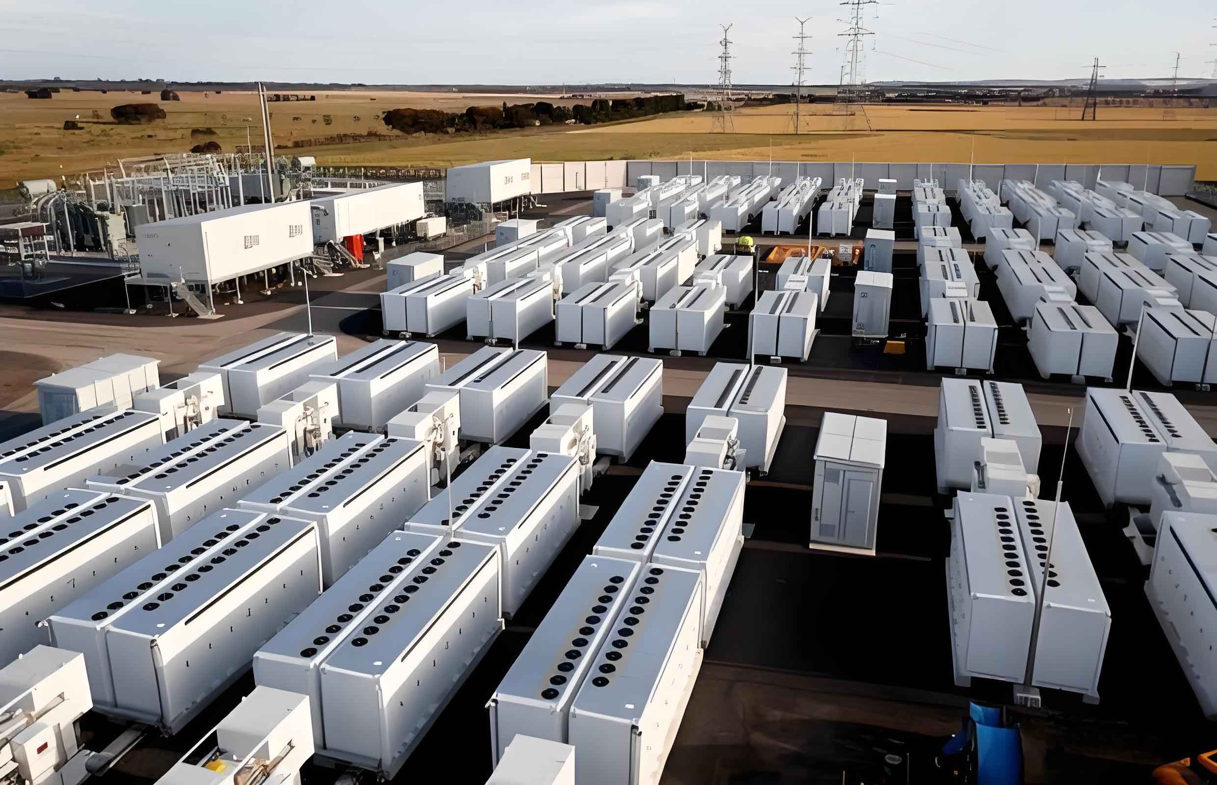
The cell energy storage system under consideration is a 100 MW/400 MWh vanadium redox flow battery plant. This facility comprises multiple storage units, each integrating battery stacks, power conversion systems, and auxiliary loads. The electrical topology includes 35 kV collection lines connecting storage units to a common bus, with step-down transformers supplying low-voltage segments for auxiliary equipment. A key aspect of this cell energy storage system is the extensive use of power electronic devices, including bidirectional energy storage converters, variable frequency drives (VFDs), and uninterruptible power supply (UPS) units. These devices, while enabling efficient energy management, introduce harmonic currents that can degrade power quality. Understanding and addressing these harmonics is crucial for the longevity and performance of the cell energy storage system.
To systematically analyze the harmonics, I first describe the system components in detail. The plant consists of four storage units, each with a specific rated capacity. For instance, three units are rated at 24 MW, and one at 28.8 MW. Each unit employs battery stacks configured for 500 kW or 800 kW power levels, with corresponding bidirectional converters. The auxiliary systems include numerous VFDs and UPS units powering electrolyte circulation pumps and critical loads. The parameters of these devices are summarized in tables to facilitate modeling. For example, the battery stack parameters include voltage ranges and current ratings, while the converter specifications detail harmonic spectra. This structured approach helps in building an accurate model for harmonic assessment in the cell energy storage system.
The harmonic sources in this cell energy storage system primarily stem from the power electronic converters. The bidirectional energy storage converters, which interface the battery stacks with the AC grid, utilize pulse-width modulation (PWM) techniques and include LC filters to attenuate harmonics. However, they still generate characteristic harmonic currents. Based on manufacturer data, the harmonic content for a 500 kVA converter is tabulated, showing significant lower-order harmonics such as the 5th, 7th, 11th, and 13th. The harmonic spectrum can be represented mathematically. For a converter, the output current often contains harmonics proportional to the switching frequency. A general formula for harmonic current magnitude is given by $$I_h = \frac{I_1}{h} \cdot k,$$ where \(I_1\) is the fundamental current, \(h\) is the harmonic order, and \(k\) is a distortion factor dependent on the converter design. For this cell energy storage system, the measured harmonic currents are provided in a table, which is essential for input into ETAP.
| Harmonic Order | Current Magnitude (A) | Percentage of Fundamental (%) |
|---|---|---|
| 2 | 10.35 | 0.90 |
| 3 | 1.97 | 0.17 |
| 4 | 1.54 | 0.13 |
| 5 | 9.83 | 0.85 |
| 7 | 6.78 | 0.59 |
| 11 | 2.81 | 0.24 |
| 13 | 2.37 | 0.20 |
| 23 | 3.92 | 0.34 |
Similarly, the VFDs and UPS units are modeled as typical 6-pulse rectifiers, which produce harmonics orders primarily at \(6n \pm 1\) (where \(n\) is an integer). For a 6-pulse drive, the harmonic current can be estimated using $$I_h = \frac{I_1}{h} \cdot \frac{\sqrt{6}}{\pi} \cdot \sin(h \cdot \alpha),$$ where \(\alpha\) is the firing angle. In this cell energy storage system, there are hundreds of such drives, leading to cumulative harmonic injection. The ETAP software allows for aggregating these sources by defining harmonic load models for each device type. I created custom models for bidirectional converters, VFDs, and UPS units, incorporating their harmonic spectra. This enables a comprehensive simulation of the entire cell energy storage system under various operating conditions.
After setting up the ETAP model, I performed harmonic load flow analysis to compute voltage and current distortion levels. The results indicate that the 35 kV bus has a voltage distortion rate of 1.6%, which complies with standards such as IEEE 519-2014, which recommends less than 3% for transmission systems. However, the low-voltage segments (e.g., 380 V buses powering auxiliary loads) exhibit severe distortion. For instance, three low-voltage buses show voltage distortion rates of 15.99%, and another shows 14.79%, far exceeding the 5% limit for low-voltage systems. The current distortion rates on these feeders are around 22%, highlighting significant harmonic pollution. The calculations are summarized in the table below, which compares different bus segments in the cell energy storage system.
| Bus Name | Voltage Level | Voltage Distortion Rate (%) | Current Distortion Rate (%) |
|---|---|---|---|
| 35 kV Main Bus | 35 kV | 1.6 | N/A |
| Low-Voltage Bus A | 380 V | 15.99 | 22.73 |
| Low-Voltage Bus B | 380 V | 15.99 | 22.73 |
| Low-Voltage Bus C | 380 V | 15.99 | 22.73 |
| Low-Voltage Bus D | 380 V | 14.79 | 22.22 |
| Auxiliary Bus 1 | 380 V | 1.46 | N/A |
| Auxiliary Bus 2 | 380 V | 1.46 | N/A |
The high distortion in low-voltage buses is attributed to the concentration of VFDs and UPS units, which act as nonlinear loads. This poses risks such as increased losses, overheating of cables, motor vibrations, and measurement errors. To mitigate these harmonics, I evaluated two common solutions: passive filters and active power filters (APFs). Passive filters use tuned LC circuits to shunt specific harmonic frequencies, but they have drawbacks like resonance with system impedance and limited adaptability. In contrast, APFs inject compensating currents dynamically to cancel harmonics, offering superior performance. For this cell energy storage system, I recommend APFs due to their ability to handle multiple harmonic orders and varying loads. A comparison is provided in the table below.
| Feature | Passive Filter | Active Power Filter |
|---|---|---|
| Working Principle | Passive, resonant at specific frequencies | Active, injects compensating currents |
| Harmonic Range | Limited to tuned orders | Covers 2nd to 50th harmonics |
| System Impact | Risk of resonance and magnification | Minimal, independent of impedance |
| Adaptability | Fixed, sensitive to load changes | Dynamic, adjusts in real-time |
| Cost | Lower initial cost | Higher initial cost |
To size the APFs, I calculated the required compensation current based on the harmonic current distortion. The formula for harmonic current is $$I_h = I_{\text{total}} \cdot \frac{\text{THD}_i}{\sqrt{1 + \text{THD}_i^2}},$$ where \(I_{\text{total}}\) is the total load current and \(\text{THD}_i\) is the current total harmonic distortion. Using data from the low-voltage buses, for Bus A with a load current of 3665 A and THDi of 22.73%, the harmonic current is $$I_h = 3665 \times \frac{0.2273}{\sqrt{1 + 0.2273^2}} \approx 812 \text{ A}.$$ Similarly, for Bus D, with 3443 A and 22.22% THDi, $$I_h = 3443 \times \frac{0.2222}{\sqrt{1 + 0.2222^2}} \approx 747 \text{ A}.$$ Therefore, I propose installing APFs rated at 900 A on each low-voltage bus to ensure adequate margin. These APFs should operate at 380 V, compensate harmonics up to the 50th order, and achieve at least 97% harmonic rejection. This design will effectively suppress harmonics in the cell energy storage system.
In addition to APF installation, I investigated the impact of transformer configurations and load arrangements on harmonic propagation. Using ETAP, I simulated scenarios with different transformer winding connections (e.g., Dy11 vs. Yy0) and found that while transformer phase shifts can attenuate some triple harmonics, they do not significantly reduce distortion from VFDs and UPS units. Isolating these nonlinear loads on dedicated transformers can prevent harmonic contamination of other sensitive loads but does not reduce the required APF capacity. Thus, for optimal performance in a cell energy storage system, a combined approach of proper system design and active filtering is recommended.
The harmonic analysis also involves evaluating interharmonic components, which may arise from frequency conversions in VFDs. Interharmonics can cause flicker and additional losses. The ETAP model can be extended to include interharmonic sources by defining frequency spectra. For this cell energy storage system, the interharmonic levels are relatively low due to the use of high-switching-frequency converters, but they should be monitored in future expansions. Furthermore, the interaction between multiple converters can lead to harmonic cancellation or amplification. Using superposition principles, the net harmonic current at a bus can be expressed as $$I_{h,\text{net}} = \sqrt{\sum_{j=1}^{n} I_{h,j}^2 + 2 \sum_{j<k} -="" \(\theta_{j}\)="" \(h\)-th="" \(i_{h,j}\)="" \(j\).="" \cos(\theta_{j}="" \theta_{k})},$$="" additive="" and="" are="" cell="" diversity="" effects,="" energy="" for="" from="" harmonic="" hence="" i_{h,j}="" i_{h,k}="" in="" is="" leading="" limited,="" magnitude="" mitigation.
Another aspect is the impact of harmonics on the battery stacks themselves. While the DC side of converters may have ripple currents, the battery stacks in a cell energy storage system are relatively tolerant due to their electrochemical nature. However, excessive harmonics on the AC side can increase losses in transformers and cables, indirectly affecting efficiency. I computed the additional losses using $$P_{\text{loss}} = \sum_{h=2}^{\infty} I_h^2 R_h,$$ where \(R_h\) is the resistance at harmonic frequency \(h\), which is higher due to skin effect. For a typical cable in this cell energy storage system, the losses increase by approximately 5-10% under harmonic conditions, underscoring the economic benefit of mitigation.
To validate the ETAP model, I compared results with analytical calculations for simple circuits. For example, for a single converter connected to a stiff bus, the voltage distortion can be approximated by $$\text{THD}_v = \frac{\sqrt{\sum_{h=2}^{\infty} (I_h Z_h)^2}}{V_1},$$ where \(Z_h\) is the system impedance at harmonic \(h\). The ETAP simulations showed close alignment, confirming model accuracy. Additionally, sensitivity analyses were performed by varying load levels and harmonic spectra to assess worst-case scenarios. This holistic approach ensures that the cell energy storage system remains compliant under all operating conditions.
In conclusion, harmonic analysis is vital for the reliable operation of cell energy storage systems. Through detailed modeling in ETAP, I identified significant harmonic distortions in low-voltage buses due to power electronic loads. By proposing active power filters with calculated ratings, the system can achieve compliance with power quality standards. This study highlights the importance of integrating harmonic mitigation early in the design phase of cell energy storage systems, especially as they scale up to support renewable integration. Future work could explore advanced control strategies for converters to minimize harmonic generation at the source, further enhancing the sustainability of such systems.
Finally, the use of software tools like ETAP enables comprehensive analysis that would be impractical manually. The tables and formulas presented here provide a framework for engineers to assess and address harmonics in similar installations. As the adoption of cell energy storage systems grows, continued focus on power quality will ensure grid stability and maximize the benefits of clean energy storage.