
The global imperative for a sustainable, low-carbon energy future has propelled the rapid integration of renewable energy sources, primarily wind and solar photovoltaic (PV) generation, into power systems worldwide. This transition, while environmentally crucial, introduces profound technical challenges to the reliable and stable operation of the electricity grid. A paramount concern is the degradation of system frequency stability. The inherent intermittency and variability of wind and solar power lead to significant and often unpredictable fluctuations in the net power injection into the grid. This exacerbates the instantaneous imbalance between electrical generation and load demand, a condition that directly manifests as frequency deviation. Maintaining frequency within a narrow, stable band (e.g., 50 Hz or 60 Hz ± 0.1-0.5 Hz) is fundamental to the secure operation of synchronous generators, protection systems, and all AC-powered equipment.
Traditionally, frequency regulation has been the domain of conventional synchronous generators—thermal (coal, gas) and hydroelectric plants. Through their rotating inertia and governor systems, they provide the primary frequency response (Inertial Response and Governor Droop Control), while their automatic generation control (AGC) systems execute secondary frequency regulation to restore system frequency to its nominal value and relieve inter-area tie-line power exchanges. However, the increasing displacement of these conventional plants by inverter-based resources (IBRs), which inherently possess little or no inertia, erodes the system’s natural resilience to disturbances. Furthermore, conventional generators are limited by their mechanical constraints: slow ramp rates (particularly thermal plants), actuation delays, and limited control precision. In a grid with high penetration of variable renewables, these limitations become critical, often leading to inadequate frequency response, increased wear and tear on conventional units, and higher risks of frequency excursions beyond safe limits.
In this evolving landscape, the cell energy storage system (CESS), particularly battery-based systems, has emerged as a transformative technology for grid services. Its unique attributes—extremely fast power response (milliseconds to seconds), high control accuracy, and bidirectional power capability—make it an almost ideal resource for frequency regulation. Unlike generators that must change their fuel input and mechanical output, a cell energy storage system can inject or absorb power purely through power electronic controls, acting as both a source and a sink to correct power imbalances almost instantaneously. This capability allows it to provide synthetic inertia and, more pertinently for this discussion, to participate with unprecedented effectiveness in secondary frequency regulation, often managed through AGC markets. The economic and reliability benefits of using a cell energy storage system for frequency regulation are now well-recognized, driving significant deployment globally, both as standalone facilities and co-located with renewable generation.
Architectural Foundations: From Cell to Grid-Scale System
To understand how a cell energy storage system participates in grid operations, one must first comprehend its hierarchical architecture. The fundamental building block is the electrochemical cell (e.g., Lithium-ion, LiFePO4, Flow battery). For utility-scale applications, these cells are systematically aggregated into larger functional units.
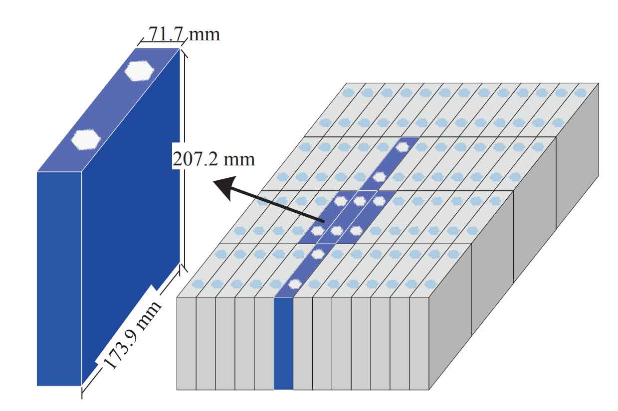
The figure illustrates the progression from a single lithium-iron-phosphate (LFP) cell to a battery module and pack, highlighting the physical aggregation necessary for scaling up capacity and voltage.
At the system level, a grid-connected cell energy storage system comprises several key subsystems integrated into a cohesive unit, often referred to as a Battery Energy Storage System (BESS). A typical functional block diagram for a unit participating in frequency regulation is as follows:
1. Battery System (BS): This is the core energy reservoir, consisting of thousands of individual cells arranged in series and parallel configurations within racks or containers to achieve the desired DC voltage and energy capacity (MWh).
2. Battery Management System (BMS): This is the guardian of the battery system. It performs critical real-time monitoring of cell voltages, temperatures, and currents. Its primary functions include state estimation (State of Charge – SOC, State of Health – SOH), ensuring safe operation within defined limits, performing cell balancing to maintain uniformity, and providing vital data to the higher-level controllers.
3. Power Conversion System (PCS): This is the critical interface between the DC world of the battery and the AC world of the grid. Typically a bidirectional Voltage-Source Converter (VSC), the PCS regulates the power flow according to setpoints. It controls the amplitude and phase of its AC-side voltage relative to the grid voltage to dictate the direction (charge/discharge) and magnitude of real (P) and reactive (Q) power exchange.
4. Energy Management System (EMS) / Frequency Regulation Controller: This is the “brain” for grid service provision. It receives signals from the grid operator (e.g., an AGC command signal like RegD or RegA) or locally measures frequency deviation. It processes these signals according to a predefined control strategy, considers the current state of the battery (SOC from BMS), and computes the optimal power setpoint (Pref) for the PCS to execute the frequency regulation service.
Scaling from a single unit (often in the range of 100 kW – 1 MW) to a large-scale cell energy storage system (tens to hundreds of MW) involves the parallel integration of multiple such BESS units. This can be done via two primary topological approaches, each with implications for control, reliability, and grid interaction, as summarized in the table below.
| Topology | Description | Advantages | Disadvantages/Challenges |
|---|---|---|---|
| Centralized (Master-Slave) | All PCS units are connected to a common DC bus before a large, centralized inverter interfaces with the medium-voltage grid. | Simplified grid interface; single point of control; potentially lower inverter costs at very large scale. | Single point of failure; complex DC bus protection; less modularity; “lump” response to grid signals. |
| Distributed (Multi-PCS Parallel) | Each BESS unit (or cluster) has its own PCS and is connected in parallel at the AC low-voltage side, often stepping up through a common transformer. | High modularity and scalability; N-1 redundancy; easier maintenance; enables differentiated control strategies per unit. | Requires sophisticated coordination to avoid circulating currents; more complex AC protection coordination. |
The distributed topology is increasingly favored for modern large-scale cell energy storage system projects due to its flexibility, reliability, and alignment with modular, containerized deployment.
Theoretical Underpinnings: How a Cell Energy Storage System Performs Secondary Frequency Regulation
Secondary frequency regulation, as part of AGC, aims to correct the steady-state error left by primary control and to restore inter-area scheduled power exchanges. The Area Control Error (ACE) is the key signal, typically defined as:
$$ ACE = \beta \Delta f + \Delta P_{tie} $$
where $\beta$ is the frequency bias factor (MW/0.1 Hz), $\Delta f$ is the frequency deviation, and $\Delta P_{tie}$ is the deviation from scheduled tie-line power flow. The AGC controller processes the ACE signal and dispatches power setpoint adjustments ($\Delta P_{ref}$) to participating resources.
When a cell energy storage system is integrated into AGC, it receives a portion of this $\Delta P_{ref}$ signal. The core actuation mechanism lies within the PCS. Consider a simplified per-phase equivalent circuit of the inverter output filter connected to the grid:
Let $\vec{U_a} = U_a \angle \delta$ be the fundamental output voltage of the PCS, $\vec{E_a} = E_a \angle 0$ be the grid voltage at the point of common coupling (PCC), and $X = \omega L$ be the inductive reactance of the coupling filter/transformer. The current $\vec{I_a}$ is given by:
$$ \vec{I_a} = \frac{\vec{U_a} – \vec{E_a}}{jX} $$
The complex power $S$ injected into the grid from the PCS is:
$$ S = P + jQ = \vec{E_a} \cdot \vec{I_a^*} $$
Substituting for $\vec{I_a^*}$ leads to the fundamental power flow equations for the inverter:
$$ P = \frac{E_a U_a}{X} \sin \delta $$
$$ Q = \frac{E_a U_a}{X} \cos \delta – \frac{E_a^2}{X} $$
For a grid-connected VSC, the phase angle difference $\delta$ is typically small. Therefore, real power transfer $P$ is predominantly controlled by modulating the phase angle $\delta$ (since $\sin \delta \approx \delta$), while reactive power $Q$ is primarily controlled by modulating the voltage amplitude ratio $U_a / E_a$. To execute a secondary frequency regulation command ($P_{ref}$), the cell energy storage system’s controller adjusts the phase angle of its output voltage relative to the grid, causing a near-instantaneous flow of active power into or out of the battery system. This rapid electrical power adjustment directly counteracts the generation-load imbalance, contributing to ACE reduction and frequency stabilization.
State of the Art in Control Strategies for Secondary Frequency Regulation
The integration of a cell energy storage system into secondary frequency control is not merely a matter of connecting hardware; it requires sophisticated control strategies to maximize effectiveness, ensure fair coordination with other resources, and protect the storage asset itself. Research has progressed along two main interconnected fronts: Coordinated Control with Conventional Generation and Internal Optimization for the Cell Energy Storage System.
1. Coordinated Control: Optimizing the Hybrid Fleet
The central question is how to optimally allocate the total AGC power requirement ($P_{AGC}$) between slow-moving conventional generators (G) and fast-acting cell energy storage systems (S). Naïve static partitioning is inefficient. Advanced strategies aim to exploit the complementary characteristics of each resource.
| Strategy Category | Core Principle | Mathematical Representation / Key Feature | Advantage | Challenge |
|---|---|---|---|---|
| Static/Dynamic Proportional Allocation | Allocate AGC signal based on a fixed or dynamically updated capacity share. | $P_{S}^{ref}(t) = k(t) \cdot P_{AGC}(t)$, $P_{G}^{ref}(t) = (1-k(t)) \cdot P_{AGC}(t)$. $k(t)$ may be updated based on CESS SOC. | Simple to implement; dynamic version respects CESS state. | Does not fully exploit speed difference; CESS may still track slow-moving trends. |
| Frequency-Domain Decomposition (Filtering) | Decompose $P_{AGC}(t)$ into high-frequency (HF) and low-frequency (LF) components using filters. | $P_{AGC}(t) = P_{HF}(t) + P_{LF}(t)$. Assign $P_{HF}(t)$ to CESS and $P_{LF}(t)$ to generators. E.g., using a low-pass filter: $P_{LF}(s) = \frac{1}{1+\tau s} P_{AGC}(s)$. | Exploits inherent speed advantage of CESS; lets generators handle gradual changes, reducing wear. | Choice of filter time constant $\tau$ is critical; requires careful tuning. |
| Optimization-Based Dispatch | Formulate a cost/benefit optimization problem considering performance, wear, and fuel costs. | Minimize: $J = \sum (w_1 \cdot ACE^2 + w_2 \cdot C_G(P_G) + w_3 \cdot C_S(P_S, SOC))$ subject to $P_G + P_S = P_{AGC}$ and other constraints. $C_S$ may model battery degradation. | Economically optimal; can explicitly model battery aging. | Computationally intensive for real-time use; requires accurate cost models. |
| Distributed/Autonomous Control | Use consensus algorithms or other distributed protocols for self-organized resource allocation. | Agents (CESS, generators) communicate locally to converge on a global power allocation that minimizes a global cost function without a central solver. | Scalable, robust to single-point failures, flexible for adding/removing resources. | Communication network requirements; ensuring convergence and stability. |
2. Internal Optimization: The SOC Management Imperative
While providing regulation, a cell energy storage system must manage its limited energy capacity. Continuous tracking of an AGC signal, which is a zero-mean random signal over time, can lead to SOC drift or operation at charge/discharge limits, rendering the system unavailable. Therefore, the internal control loop must modify the raw AGC command ($P_{AGC}^{raw}$) to produce the final battery setpoint ($P_{ref}$) that both supports the grid and maintains the SOC within a sustainable, effective range. This is often termed “SOC feedback” or “state-of-charge recovery.”
Advanced strategies move beyond simple PI control on SOC error. They embed intelligence to adapt the SOC recovery strength based on the grid’s need and the battery’s state.
a) Fuzzy Logic Control: This approach uses linguistic rules to determine the power adjustment $\Delta P_{SOC}$ based on both the SOC level and its trend. For example:
IF SOC is “Low” AND d(SOC)/dt is “Negative,” THEN apply a “Large Positive” charging bias.
IF SOC is “Medium” AND ACE is “Large,” THEN apply a “Very Small” bias.
The output $\Delta P_{SOC}$ is added to the frequency-regulation component:
$$ P_{ref}(t) = P_{FR}(t) + \Delta P_{SOC}(t) $$
where $P_{FR}(t)$ could be the filtered high-frequency component of $P_{AGC}^{raw}(t)$. This method is robust and handles nonlinearities well without a precise mathematical model.
b) Adaptive Gain Based on Nonlinear Functions: A more analytical approach uses a nonlinear function, like a logistic or sigmoid function, to dynamically adjust the gain applied to the SOC error. The power setpoint can be formulated as:
$$ P_{ref}(t) = P_{AGC}^{raw}(t) – K_{SOC} \cdot f(SOC(t) – SOC_{target}) $$
where $f(\cdot)$ is a bounded, smooth function (e.g., $f(x)=2/(1+e^{-ax})-1$). The gain $K_{SOC}$ itself can adapt based on the magnitude of ACE—small during large frequency deviations to prioritize grid support, and larger during quiet periods to prioritize SOC recovery. This creates a seamless, adaptive trade-off between regulation performance and battery state management.
c) Model Predictive Control (MPC): This is the most sophisticated approach, treating SOC management as a finite-horizon optimization problem. At each control interval, the MPC solves:
$$ \min \sum_{k=0}^{N-1} \left( \| ACE_{pred}(k) \|^2 + \lambda \| SOC(k) – SOC_{ref} \|^2 + \gamma \| \Delta P_{ref}(k) \|^2 \right) $$
subject to: Power balance, CESS power and energy limits, and SOC limits. It uses a prediction model of grid ACE (or regulation signal) and the CESS to find the optimal sequence of $P_{ref}$ commands that minimizes a cost function balancing regulation error, SOC deviation, and control effort. While computationally demanding, it provides optimal performance with explicit constraint handling.
Future Trajectories and Concluding Perspectives
The pathway for large-scale cell energy storage system integration into grid frequency regulation is marked by both tremendous promise and ongoing challenges. The future development will be shaped by advancements across technical, economic, and regulatory domains.
Technical Evolution: The next generation of control strategies will leverage artificial intelligence and machine learning more profoundly. Deep reinforcement learning agents could learn optimal policies for coordinated dispatch and SOC management directly from operational data, adapting to changing grid conditions and battery degradation. Furthermore, the concept of a cell energy storage system will expand to include hybrid storage systems (e.g., battery + supercapacitor), where ultra-fast storage handles the very highest frequency components, further optimizing the use of battery cycles and enhancing overall response.
Grid-Forming Capabilities: Moving beyond just following AGC signals, future cell energy storage systems equipped with grid-forming inverters will be able to autonomously establish and regulate grid voltage and frequency, providing essential stability services in grids with very high IBR penetration. This represents a paradigm shift from grid-following to grid-supporting and grid-forming operation.
Market and Regulatory Frameworks: For widespread adoption, markets must properly value the speed and accuracy of a cell energy storage system. Performance-based compensation mechanisms (e.g., pay-for-performance in U.S. ISO markets) that reward precision and fast response are crucial. Standardization of grid codes to define the required response characteristics for storage participating in frequency regulation is also necessary to ensure interoperability and predictable system behavior.
System-Level Planning and Sizing: Determining the optimal capacity, power rating, and placement of large-scale cell energy storage systems for frequency regulation requires advanced planning tools that co-optimize with other resources, considering future renewable growth, retirement of conventional plants, and the evolving inertia landscape.
In conclusion, the integration of large-scale cell energy storage systems into secondary frequency regulation is not merely an incremental improvement but a fundamental enabler for a secure, reliable, and renewable-dominant power grid. Its ability to provide fast, precise, and flexible power adjustments directly addresses the core stability challenge introduced by variable renewables. While significant research has matured the control strategies for coordination and internal optimization, the frontier continues to advance with AI, grid-forming technologies, and evolving market structures. The continued decline in battery costs, coupled with the escalating need for grid flexibility, unequivocally positions the cell energy storage system as a cornerstone technology in the ongoing transformation of the world’s electric power systems.