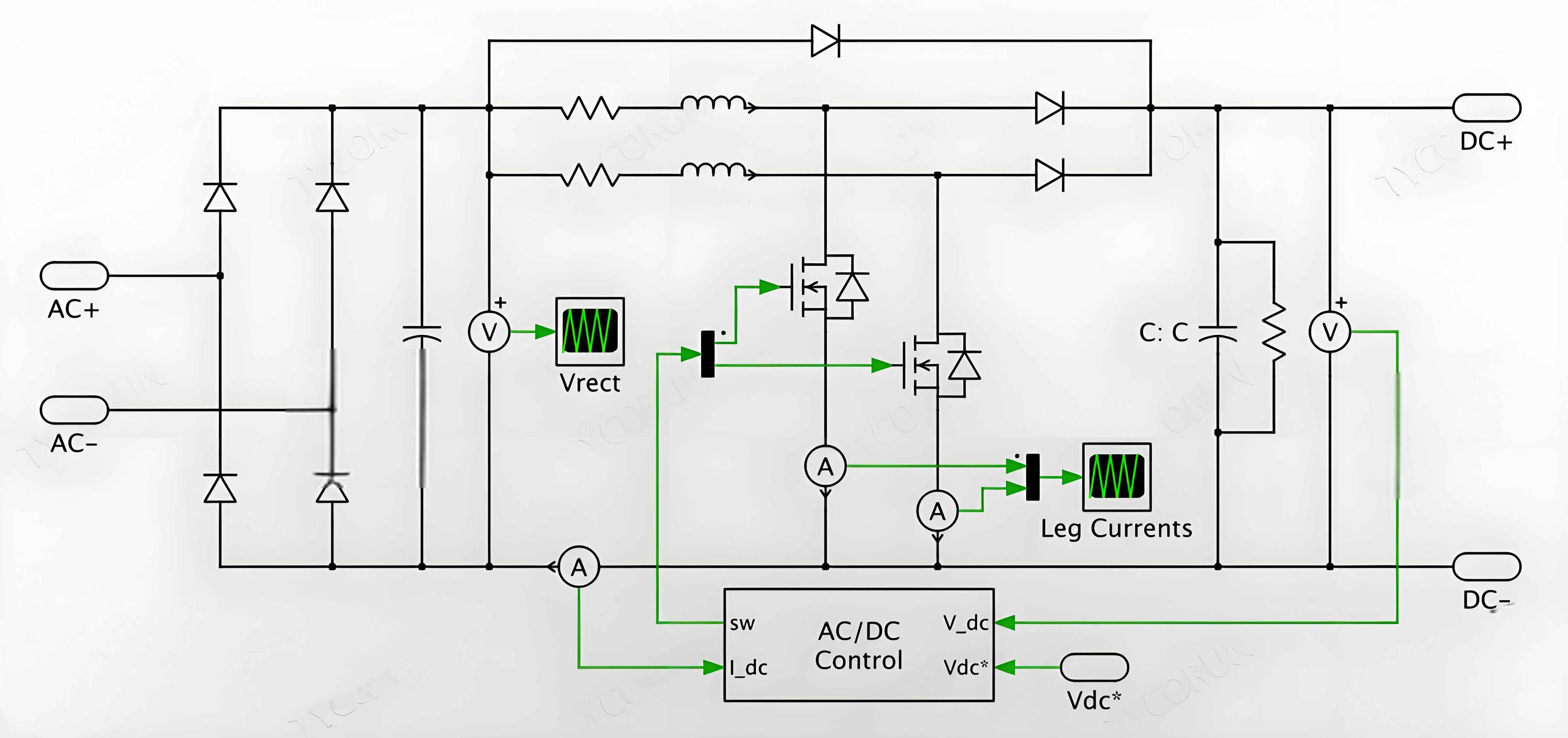
The grid-connected control of single-phase inverters. The main goal of grid-connected control is to ensure effective control of solar inverter’s grid-connected current, enabling it to track the frequency and phase changes of the grid voltage, and reduce the total distortion of the grid-connected current to minimize the impact of harmonic currents on the grid.

1. Introduction
The grid-connected control of solar inverter power supplies is crucial in distributed power generation systems. It requires the selection of a suitable filter and a current control method to achieve high-performance grid connection.
2. Design of Output Filter for Single-Phase Grid-Connected Inverter
2.1 L-Type Filter
The L-type filter uses a single inductor as the filtering component. It has a simple structure and good control characteristics, but its filtering effect for switching ripples is limited.
2.2 Π-Type Filter
The Π-type filter provides a low-impedance path for high-frequency switching ripple currents, reducing the injected ripple current into the grid. However, it is a third-order system with stability design challenges.
2.3 Split Capacitor-Type L Filter
The split capacitor-type L filter replaces the filtering capacitor in the Π-type filter with two parallel capacitors. By selecting appropriate inductance and capacitance parameters, it can reduce the filter to a first-order system, simplifying the control loop design.
3. Current Hysteresis Control for Single-Phase Grid-Connected Inverter
3.1 Principle Analysis of Current Hysteresis Control
Current hysteresis control is a widely used current tracking control method. It has the advantages of simple structure, fast response, automatic peak current limitation, and unconditional stability.
3.2 Switching Frequency Analysis of Current Hysteresis Control Inverter
The switching frequency of the current hysteresis control inverter is related to the hysteresis width, output filter inductance, DC source voltage, and grid voltage.
3.3 Design and Implementation of Fixed Switching Frequency Current Hysteresis Control
To achieve a fixed switching frequency, the hysteresis width needs to be adjusted according to the grid voltage. This can be implemented by adding a real-time calculation circuit for the hysteresis width.
4. Design of Constant Frequency Current Hysteresis Control Inverter Based on Switch Time Prediction
4.1 Implementation Principle
By predicting the switching time of the solar inverter based on the difference between the inductor current and the reference current, the control circuit can operate without the need to set the hysteresis width.
4.2 Steady-State Performance
The peak value of the ripple current is not fixed but changes with the grid voltage and the reference current signal. The duty cycle also changes with the grid current and the reference current signal.
4.3 Transient Performance
The dynamic response speed of the proposed control strategy is similar to that of the traditional current hysteresis control, with a maximum delay of 1/4 of the switching period.
4.4 Influence of Inductance Parameter Variation on Performance
When the actual value of the output inductance deviates from the design value, the switching frequency may deviate from the set value, but the deviation is small for medium and small power grid-connected inverters.
4.5 Design of Phase-Locked Loop
A digital phase-locked loop is used to track the grid voltage and obtain the synchronous signal for the reference current.
5. Experimental Results
The experimental results show that the grid-connected inverter with the proposed control strategy can output sinusoidal current, has a fast transient response, and a constant switching frequency.
In summary, this chapter analyzes the output filter and current hysteresis control method for single-phase grid-connected inverters, and proposes a constant frequency current hysteresis control strategy based on switch time prediction. The experimental results verify the effectiveness of this strategy.
The following is a summary of the key points in tabular form:
| Topic | Key Points |
|---|---|
| Output Filter Design | – L-Type Filter: simple structure, limited filtering effect – Π-Type Filter: better filtering effect, third-order system – Split Capacitor-Type L Filter: simplifies control loop, reduces to first-order system |
| Current Hysteresis Control | – Principle: current tracking, automatic peak current limitation – Switching Frequency: related to multiple factors – Fixed Switching Frequency: adjust hysteresis width based on grid voltage |
| Constant Frequency Current Hysteresis Control | – Implementation Principle: predict switching time, no need for hysteresis width – Steady-State Performance: ripple current and duty cycle change with voltage and current signals – Transient Performance: similar to traditional control, small delay – Inductance Parameter Variation: small impact on switching frequency for medium and small inverters – Phase-Locked Loop: track grid voltage for synchronous signal |
| Experimental Results | – Sinusoidal current output, fast transient response, constant switching frequency |
