
With environmental issues and the continuous depletion of fossil fuel reserves, renewable energy sources such as wind and solar energy have gradually become the main research directions. However, photovoltaic and wind power generation are greatly affected by terrain, climate, and the environment, resulting in fluctuations, intermittency, and difficulty in predicting active power output.
The battery energy storage system can effectively regulate the active power of the system, thereby improving the stability and reliability of the microgrid. When multiple battery energy storage units operate in parallel in the system, there may be situations where one energy storage unit is overcharged or discharged, affecting the service life of some energy storage units, causing other energy storage units to be idle, and reducing the overall efficiency of the system. Therefore, studying the SOC equilibrium control of multiple battery energy storage units has important application prospects and theoretical significance.
We studied the SOC equalization control of a battery energy storage system based on cascaded PWM converters. Adopting an improved droop control SOC balancing control strategy, the droop coefficient in the energy storage system is set by detecting the state of charge of each energy storage unit, thereby changing the output current of the energy storage unit and achieving SOC balancing of each energy storage unit. However, changing the sag coefficient will have an impact on the stability of battery energy storage. By adopting an improved droop control strategy that changes the reference voltage, energy balance is achieved for multiple double layer capacitors in a low-voltage bipolar DC microgrid.
This article focuses on the problem of SOC imbalance and output voltage fluctuation among multiple parallel energy storage units in a battery energy storage system. A battery energy storage system model is built, and traditional control methods are improved. A SOC balance control strategy based on fuzzy theory is adopted, and dual closed-loop control technology is used to stabilize the DC side voltage, completing simulation verification.
1.Battery energy storage system
1.1 Structure of battery energy storage system
The structure of the battery energy storage system is shown in Figure 1.
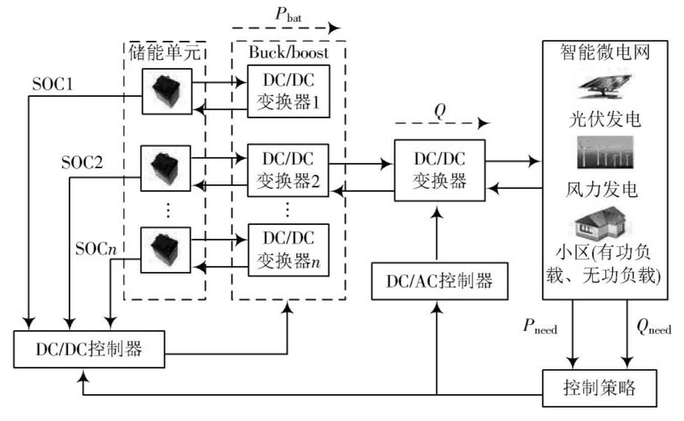
The system consists of four parts: battery pack, controller, inverter, and microgrid. Firstly, by collecting, analyzing, and processing microgrid data, the required active and reactive power for the microgrid can be obtained. The main research object of this article is the DC/DC controller, which mainly processes the active power of the microgrid, outputs control commands, and controls the charging and discharging of the battery energy storage system. When the active load in the microgrid is too large and there is a demand for active power, the energy storage system is controlled to discharge and generate active power. At the same time, the SOC of the energy storage unit is detected to control it to reach equilibrium; On the contrary, when there is an excess of active power in the microgrid, the energy storage system is controlled to charge, absorb active power, and detect the SOC of the energy storage unit to achieve equilibrium.
1.2 Topological structure of battery energy storage system
Choosing a suitable topology structure for energy storage systems is of great significance in reducing design redundancy and extending the service life of battery packs. The topology selected in this article is shown in Figure 2.
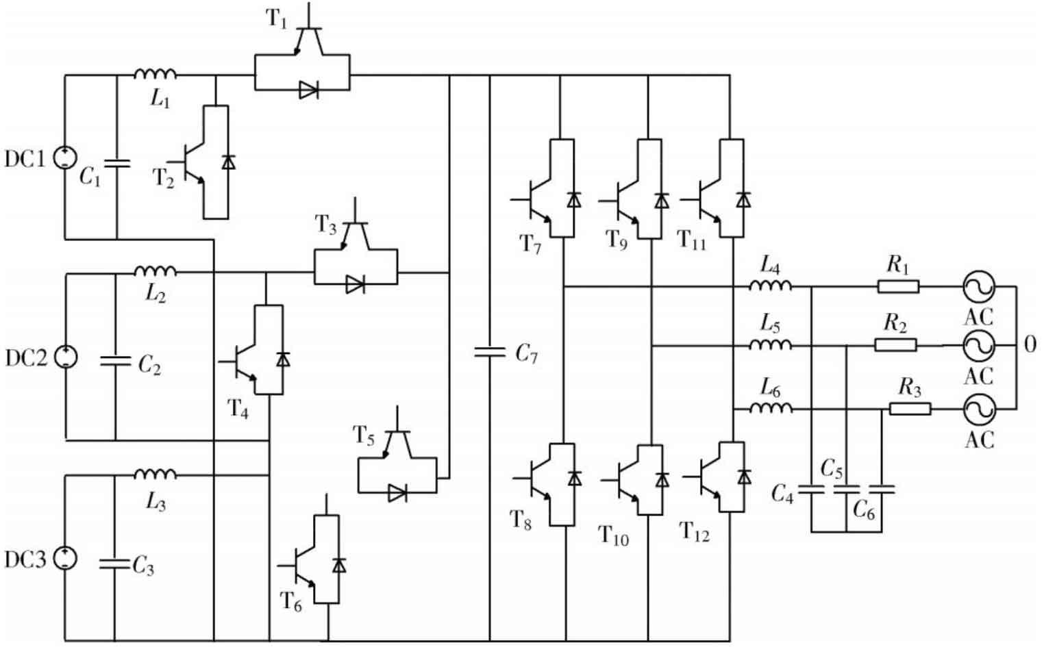
This topology consists of a battery pack, a bidirectional Boost ⁃ Buck circuit, a bidirectional PWM rectifier, an LC filter, and an AC microgrid. This topology structure with bidirectional Boost ⁃ Buck boost and boost modules has strong adaptability, which can achieve charge and discharge management of multiple parallel energy storage unit modules; Due to the fact that the Boost ⁃ Buck module can achieve DC voltage rise and fall, the capacity of the energy storage unit is more flexible; Suitable for microgrids with highly volatile distributed power sources such as wind power and photovoltaic, to suppress active power fluctuations.
1.3 Power Control Strategy for Battery Energy Storage System
This article separately controls the DC side and inverter side, with the DC/DC converter controlling the active power and stabilizing the DC side voltage, and the DC/AC converter controlling the reactive power. This article mainly studies the active power of the system, and the control strategy is shown in Figure 3..
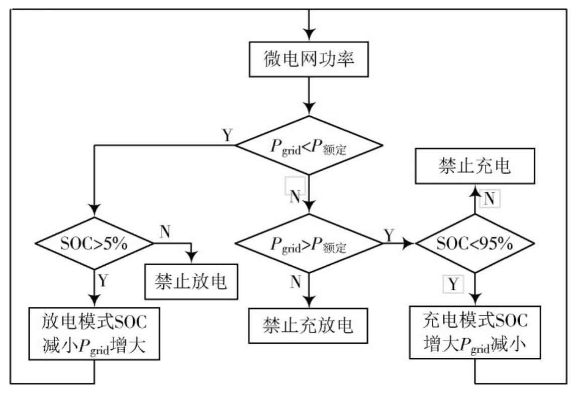
From Figure 3, it can be seen that when the SOC of the battery exceeds the upper limit, charging is prohibited; When the SOC of the battery is below the lower limit, discharge is prohibited; When the SOC of the battery is within the normal range of 5% ≤ SOC ≤ 95%, the battery absorbs or outputs power. The basic relationship between the actual power of the microgrid, the rated power of the microgrid, and the charging and discharging of the battery is as follows:
1) The actual power of the microgrid is greater than the rated power, and the microgrid is “peak shaving” and the battery is charged.
2) The actual power of the microgrid is less than the rated power, and the microgrid is “valley filled” and the battery is discharged.
3) The actual power of the microgrid is equal to the rated power, and the battery is not working.
2. SOC Equalization Control Strategy for Battery Energy Storage Units
This article takes the discharge mode of the battery energy storage system as an example to study the SOC balance control strategy of the battery energy storage unit. The basic idea of SOC balance control for battery packs is that batteries with larger SOC output more energy, while batteries with smaller SOC output less energy, thereby achieving SOC balance. Changing the reference voltage or changing the controller parameters in the dual closed-loop control can achieve battery output energy control and achieve SOC balance. However, the former will have an impact on system stability, so this article adopts the method of changing the reference voltage.
2.1 SOC evaluation of battery energy storage units
The battery energy storage system is regulated according to the SOC of the energy storage unit, so it is necessary to evaluate the SOC. Although many methods have been proposed to measure the SOC of battery energy storage units, the charge accumulation method is the most commonly used technique, and it is relatively simple to estimate the SOC of each energy storage unit, so this method is adopted. The algorithm is as follows:

In the formula: Ce_ I is the capacity of the energy storage unit; SOCit=0 is the initial remaining capacity; Ibat_ I is the output current of the energy storage unit.
2.2 Fuzzy control link
Fuzzy Control is a rule-based nonlinear control theory. The design rules of fuzzy controllers are usually based on the designer’s existing experience and knowledge, do not require precise mathematical models, have strong robustness, real-time performance, and are easy to implement digitally. This article uses fuzzy control to determine the reference voltage.
The input value Xk is the ratio of the remaining power of each battery to the average remaining power, expressed as follows:
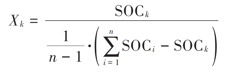
In the formula: SOCk is the remaining electricity of the selected energy storage unit; SOCi is the remaining power of a separate energy storage unit.
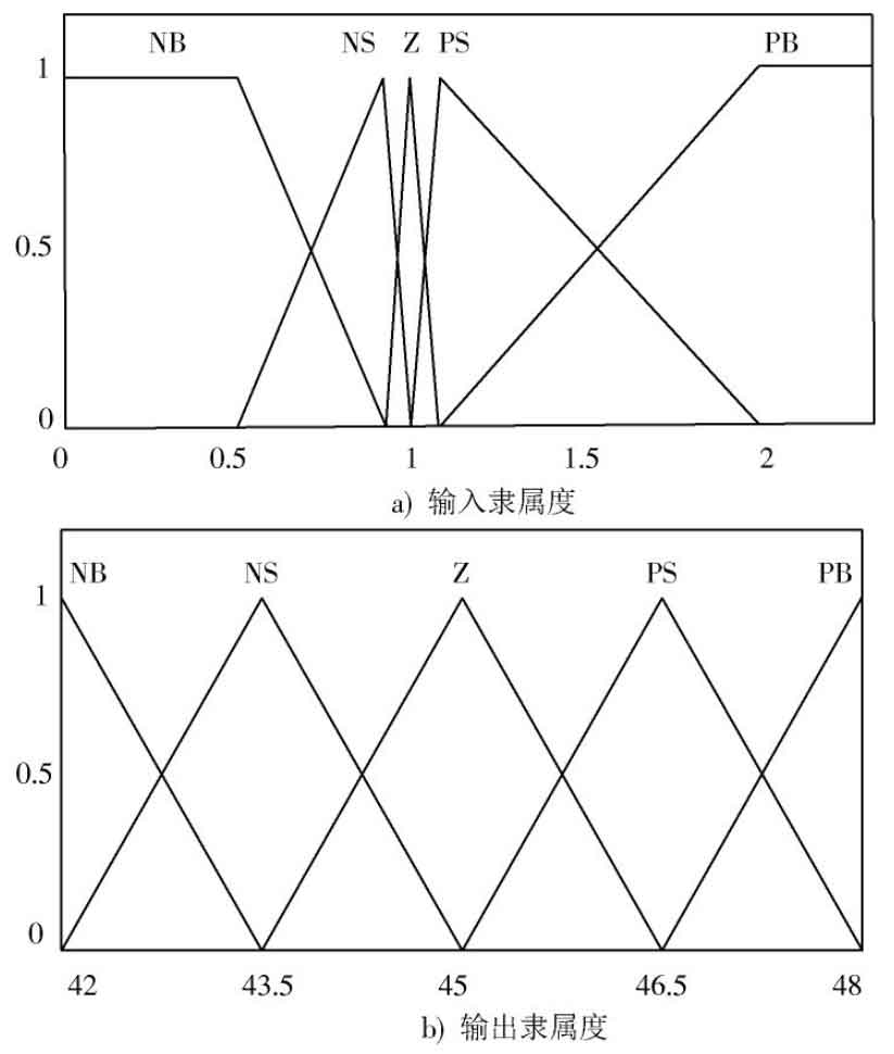
The system is a single input single output system, and this article selects Xk as the control signal to directly adjust Vdc through fuzzy rules. There are a total of 2 variables in the input and output, and their fuzzy set is defined as {PB, PS, Z, NS, NB}, that is, {negative large, negative small, zero, positive small, positive large}. In an ideal scenario, establish membership functions for Xk and Vdc respectively, as shown in Figure 4.
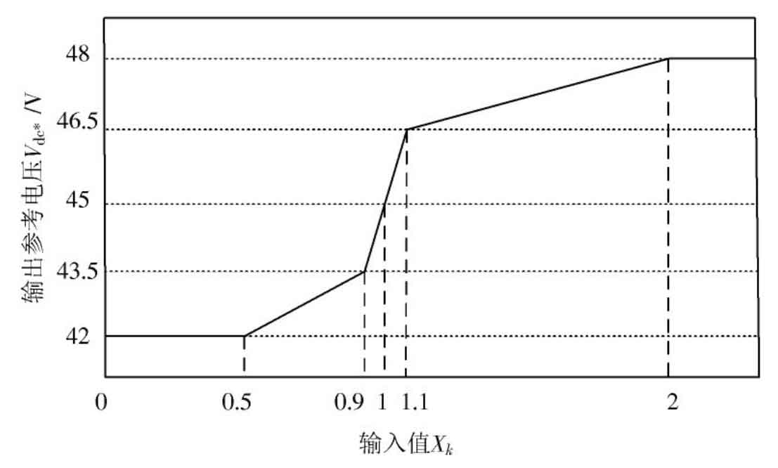
Using the Mamdani fuzzy inference method, with the goal of quickly reaching the given value of the output voltage, establish fuzzy rules, and obtain the relationship between the ideal input value Xk and the output reference voltage Vdc *, as shown in Figure 5.
2.3 SOC Balanced Control Strategy Based on Fuzzy Control
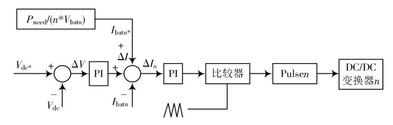
Figure 6 shows the control block diagram of a traditional battery energy storage system. Among them, the outer ring is the DC output voltage ring, and the reference voltage Vdc * is the given value. The difference between the reference voltage Vdc and the output voltage Vdc is controlled by PI to obtain the fluctuating current Δ Iv, the quotient of the required power Pneed of the microgrid and the current of the energy storage unit obtained through detection and calculation is used as the reference current Ibat *, Δ The sum of Iv and Ibat * serves as the reference current value for the final energy storage unit. The inner ring is the current ring of the energy storage unit, which outputs the difference between the measured current Ibat of the energy storage unit and the final reference current.
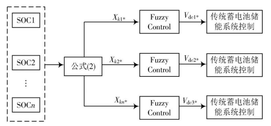
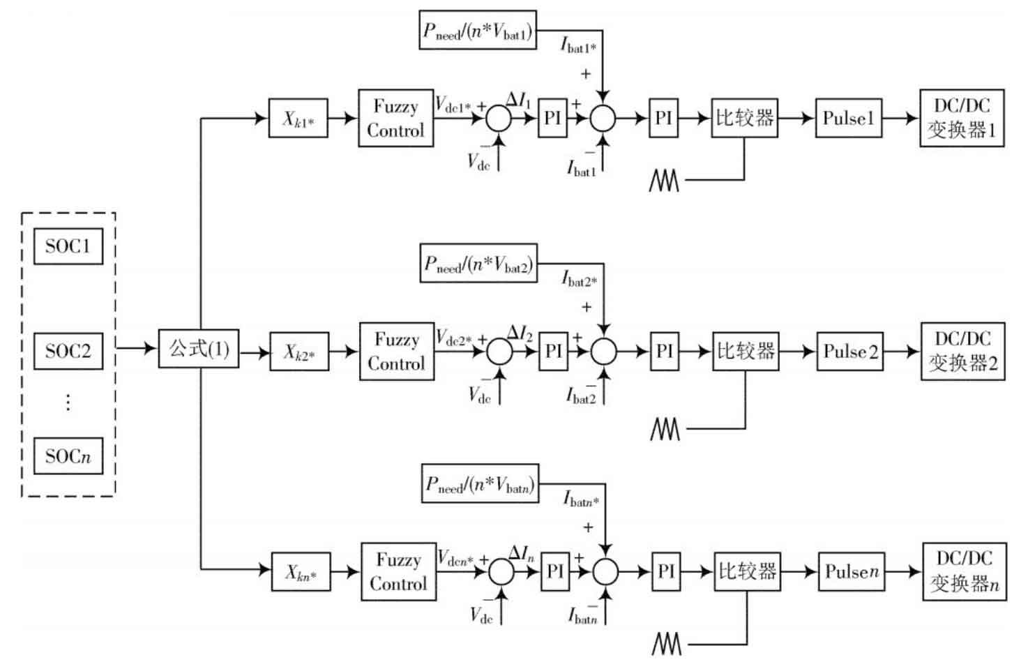
Figure 7 shows the SOC balance control process of the battery energy storage unit, and Figure 8 shows the overall control diagram of the improved battery energy storage system. Unlike traditional voltage and current dual closed-loop control systems, this article adds a fuzzy control link based on SOC to the traditional control method, detects the SOC of the energy storage unit, and then obtains the reference voltage Vdc * through fuzzy control, Thus, the voltage at the DC output end and the output current of the energy storage unit are changed, ensuring that the output voltage tends to be stable while achieving SOC equilibrium. The expression for output voltage is:
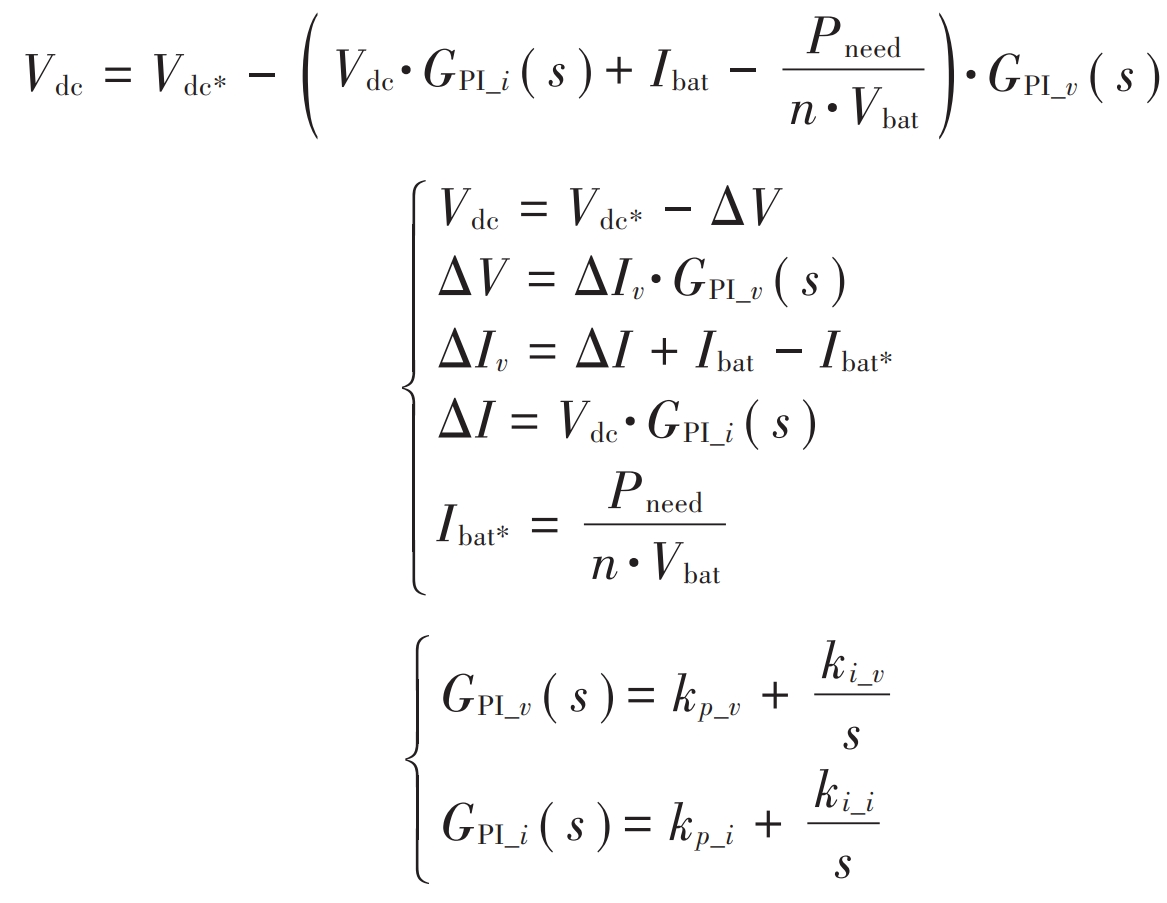
In the formula, Vdc and Vdc * are the output voltage and reference output voltage of the battery energy storage system, respectively; Ibat and Ibat * are the output current and reference output current of the energy storage unit, respectively; GPI_ (v s) is the transfer function of the output voltage PI controller; GPI_ (i s) is the transfer function of the PI controller for the output current of the energy storage unit; Pneed is the active power required by the microgrid; Δ V is the voltage deviation; Δ Iv is the current fluctuation caused by voltage deviation; Δ I is the current deviation.
3. Simulation results
In order to verify the correctness and effectiveness of the above theory, a simulation model was built in Matlab/Simulink, which has three sets of parallel energy storage units with different initial remaining electricity levels. Firstly, the application of traditional control in the battery energy storage system was simulated, and then the effect of the overall control method on the SOC balance of the energy storage unit and the impact on the output voltage of the battery energy storage system were verified by adding a SOC balance link based on fuzzy control.
The main simulation parameters are shown in Table 1.
| Parameter | Value |
| Rated output voltage on DC/V | 45 |
| Battery pack voltage/V | 24 |
| Initial remaining power SOC1, SOC2, SOC3 | 61%,59%,57% |
| Battery side inductance/μH | 1 |
| Battery side capacitance/μF | 0.1 |
| Output capacitance/μF | 470 |
Figure 9 shows the simulation waveform obtained from the control of a traditional battery energy storage system. From Figure 9, it can be concluded that the output current of the three groups of energy storage units remains basically the same, so the SOC of the energy storage unit is not balanced, and the output voltage of the energy storage system remains unchanged.
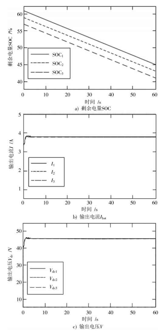
Figure 10 shows the simulation waveform obtained from SOC equalization control based on fuzzy theory. From Figure 10, it can be concluded that the output current and voltage of the energy storage unit can change correspondingly according to the SOC of the energy storage unit. When the difference in SOC decreases, the output current and voltage of the energy storage unit tend to be equal.
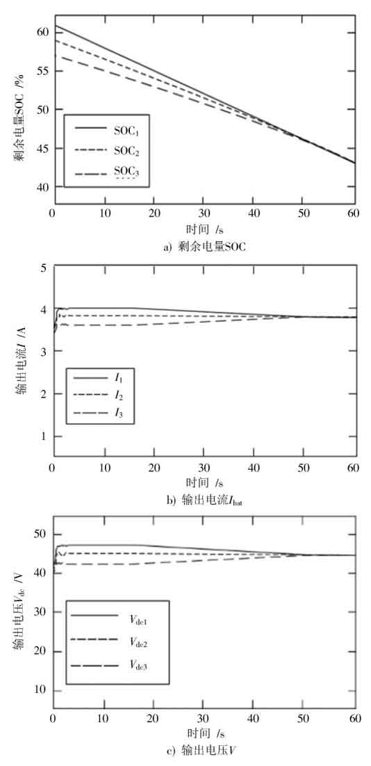
This method adjusts the output voltage of the energy storage unit within a certain range while achieving SOC balance, so that the output voltage is ultimately maintained at 45 V.
4.Conclusion
The battery energy storage system can effectively regulate the active power of the system, thereby improving the stability and reliability of the microgrid. This paper adopts a fuzzy improved dual closed-loop SOC balance control strategy. On the basis of the dual closed-loop control method, by adding a fuzzy control link to the SOC, the reference voltage is adjusted within a certain range to control the DC/DC converter to change the output current of the battery energy storage unit, ultimately achieving balance in the remaining electricity while maintaining stable output voltage of the energy storage system. Compared with the traditional control strategy without the addition of fuzzy control, the simulation results verify that the improved battery energy storage control strategy can effectively solve the problem of imbalanced SOC of energy storage units when multiple energy storage units are running in parallel in the battery energy storage system, and at the same time, make the output reference voltage of the battery energy storage system ultimately reach stability.