
The stability and operational safety of utility-scale photovoltaic power plants, particularly those equipped with tracking systems, are critically challenged by high wind loads. Under strong wind conditions, solar panels can experience significant dynamic swaying displacements. These displacements not only reduce power generation efficiency by misaligning the panels from their optimal sun-tracking angle but also induce long-term dynamic fatigue in the support structures, potentially leading to catastrophic structural failures. Therefore, accurate field monitoring of these wind-induced dynamic responses in solar panels is paramount for structural safety assessment, design optimization, and operational risk management.
Traditional methods for structural displacement monitoring, such as Linear Variable Differential Transformers (LVDTs), accelerometer-based integration, and Global Navigation Satellite System (GNSS) receivers, face significant limitations when applied to solar panels in extreme wind environments. Contact-based sensors like LVDTs are difficult to install on large, vibrating panel surfaces and can interfere with the panel’s natural motion. Accelerometer-based displacement derivation is prone to significant integration drift errors when measuring large-amplitude, low-frequency sway motions typical of solar panels. While GNSS can provide absolute positioning, its accuracy at the centimeter level may be insufficient for precise deformation analysis, and its sampling rate is often too low to capture rapid dynamic transients. Consequently, there is a pressing need for a non-contact, high-frequency, and accurate monitoring technique capable of capturing the full-field dynamic displacement of solar panels under service loads.
In this context, Large-Scale Particle Image Velocimetry (LS-PIV) emerges as a highly promising solution. Originally developed for fluid velocity field measurement, the core principle of PIV—tracking the motion of natural or seeded patterns between successive images—has been successfully adapted for measuring solid deformations in geotechnical and structural engineering. LS-PIV extends this capability to field-scale applications using consumer-grade digital cameras, making it a cost-effective and practical tool. This study proposes and validates a comprehensive LS-PIV-based methodology for the field monitoring of strong wind-induced sway displacements in single-axis solar tracking systems. We detail the image processing algorithms, implement them in a Python-based processing pipeline, and present results from a field campaign conducted on a solar power plant under wind conditions exceeding 20 m/s.
Algorithmic Foundation of LS-PIV for Solar Panel Monitoring
The successful application of LS-PIV to monitor solar panels hinges on robust image processing algorithms. Unlike laboratory PIV, field applications using consumer cameras must contend with variable lighting, lack of controlled seeding, and lens distortions. Our processing chain addresses these challenges through sequential stages: preprocessing, matching, and postprocessing.
Image Preprocessing
Raw images are first converted to grayscale to simplify subsequent calculations, using the standard luminance formula:
$$Grey = 0.299 \times R + 0.587 \times G + 0.114 \times B$$
where \(R, G, B\) are the pixel intensity values for the red, green, and blue channels, respectively, and \(Grey\) is the resulting grayscale value.
To mitigate noise from sensor grain and subtle lighting variations, a 2D Gaussian filter is applied. The Gaussian kernel \(G(x,y)\) is defined as:
$$G(x,y) = \frac{1}{2\pi\sigma^2} e^{-\frac{x^2+y^2}{2\sigma^2}}$$
where \(\sigma\) is the standard deviation controlling the blur intensity. Convolving this kernel with the image suppresses high-frequency noise.
Finally, histogram equalization is employed to enhance image contrast, especially under non-uniform lighting conditions common in outdoor monitoring of solar panel arrays. For an image with \(L\) total gray levels, the transformation is given by:
$$s_k = \sum_{j=0}^{k} \frac{n_j}{n}, \quad k = 0, 1, …, L-1$$
where \(n\) is the total number of pixels, \(n_j\) is the number of pixels with gray level \(j\), and \(s_k\) is the new mapped value for the original gray level \(k\). This step ensures that features on the solar panel surface, such as module frames, junction boxes, and textural patterns, have sufficient contrast to serve as effective “tracers” for the LS-PIV algorithm.
Image Matching via Cross-Correlation
The core of displacement calculation is identifying the motion of small interrogation windows between two consecutive frames. We employ the Sum of Squared Differences (SSD) algorithm for its computational efficiency and reliability. For two image frames represented by grayscale matrices \(\mathbf{G_1}\) and \(\mathbf{G_2}\), the SSD \(R_{SSD}\) for a window of size \(M \times N\) pixels at a candidate displacement \((\Delta x, \Delta y)\) is calculated as:
$$R_{SSD}(\Delta x, \Delta y) = \sum_{i=0}^{M-1}\sum_{j=0}^{N-1} [g_1(i, j) – g_2(i+\Delta x, j+\Delta y)]^2$$
Here, \(g_1\) and \(g_2\) are the grayscale value functions of the interrogation window in the first and second frame, respectively. The displacement vector for that window is determined by finding the \((\Delta x, \Delta y)\) that minimizes \(R_{SSD}\). This process is repeated for a grid of interrogation windows covering the entire region of interest on the solar panel, generating a dense vector field of apparent motion.
Image Postprocessing for Vector Validation
The raw displacement vectors from cross-correlation require refinement to remove spurious matches. A signal-to-noise ratio (SNR) filter is first applied. The SNR for a correlation peak is defined as:
$$SNR = \frac{P_1}{P_2}$$
where \(P_1\) is the primary correlation peak value and \(P_2\) is the second-highest peak. Vectors with an SNR below a defined threshold (e.g., 1.5) are considered unreliable and discarded.
To achieve sub-pixel displacement accuracy, a three-point Gaussian peak fitting is performed around the integer-peak location. The sub-pixel offsets \(\Delta x_{sub}\) and \(\Delta y_{sub}\) are calculated as:
$$\Delta x_{sub} = \frac{\ln(C_{i-1,j}) – \ln(C_{i+1,j})}{2[\ln(C_{i-1,j}) – 2\ln(C_{i,j}) + \ln(C_{i+1,j})]}$$
$$\Delta y_{sub} = \frac{\ln(C_{i,j-1}) – \ln(C_{i,j+1})}{2[\ln(C_{i,j-1}) – 2\ln(C_{i,j}) + \ln(C_{i,j+1})]}$$
where \(C_{i,j}\) is the correlation coefficient at the integer peak location \((i, j)\).
Finally, gaps left by the SNR filter are filled using Inverse Distance Weighting (IDW) interpolation from surrounding valid vectors. The interpolated value \(Z\) at point \((x,y)\) is:
$$Z(x,y) = \frac{\sum_{i=1}^{N} Z_i / D_i^p}{\sum_{i=1}^{N} 1 / D_i^p}$$
where \(Z_i\) are the \(N\) neighboring valid vector components, \(D_i\) is the distance to the \(i\)-th neighbor, and \(p\) is the power parameter (typically set to 2).
Camera Calibration for Accurate Metric Conversion
A critical step for converting pixel displacements to real-world metric units is camera calibration. We employ Zhang’s plane-based calibration method to correct for lens distortion and establish the precise relationship between image coordinates and world coordinates on the plane of the solar panel. A chessboard calibration target of known dimensions (e.g., 200 mm grid spacing) is rigidly attached to the solar panel structure, ensuring it moves as a rigid body with the panel. Multiple images of the target from the monitoring camera’s viewpoint are processed to compute the camera’s intrinsic matrix (focal length, principal point) and distortion coefficients (radial and tangential). This calibration enables the accurate projection of the 2D image displacement field onto the physical plane of the solar panel, correcting for perspective and lens effects that would otherwise introduce significant measurement error, especially at the edges of the panel.
Field Application and Monitoring Strategy for Solar Panels
The proposed LS-PIV methodology was deployed at a large-scale photovoltaic power plant featuring single-axis horizontal tracking systems. The site is characterized by a high-wind environment, making it an ideal candidate for studying wind-structure interaction on solar panels.
Site Characteristics and Wind Environment
The solar panel arrays consist of single-axis tracking units with a chord length of approximately 4.85 meters. An analysis of historical wind data from the site was conducted to understand the loading regime. The wind speed distribution was modeled using a two-parameter Weibull distribution, whose probability density function is:
$$f(v) = \frac{k}{c} \left( \frac{v}{c} \right)^{k-1} \exp\left[-\left( \frac{v}{c} \right)^k \right] \quad (v \geq 0)$$
where \(v\) is the wind speed, \(k\) is the shape parameter, and \(c\) is the scale parameter. For the site, the parameters were estimated as \(k \approx 1.69\) and \(c \approx 6.88 \, \text{m/s}\). This indicates a wind regime with frequent moderate winds and a non-negligible probability of extreme events. The probability of exceeding a given wind speed \(v_0\) is:
$$P(v > v_0) = \exp\left[-\left( \frac{v_0}{c} \right)^k \right]$$
Analysis showed that while winds are most common between 4-12 m/s, speeds exceeding 20 m/s have a measurable probability of occurrence, necessitating robust monitoring.
| Wind Speed \(v_0\) (m/s) | Exceedance Probability \(P(v > v_0)\) (%) |
|---|---|
| 4 | 67.04 |
| 8 | 27.52 |
| 12 | 7.73 |
| 16 | 1.56 |
| 20 | 0.23 |
| 24 | 0.03 |
Monitoring Setup and Data Acquisition
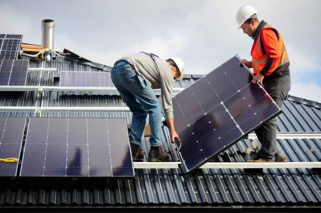
To capture the most critical dynamic response, the solar panel was intentionally positioned at a 45-degree angle, facing away from the prevailing high-wind direction (Northwest). This orientation subjects the panel to maximum uplift (suction) forces, representing a worst-case scenario for instability. The calibration target was securely mounted on the panel’s frame. A consumer-grade digital camera capable of 4K resolution video at 60 frames per second was used for monitoring. The camera was mounted on a sturdy tripod placed inside a vehicle to shelter it from the wind, ensuring stable image acquisition without external vibration. Video sequences were recorded during periods of varying wind intensity, as measured by a nearby meteorological tower.
Data Analysis and Results for Solar Panel Displacement
The recorded videos were decomposed into image sequences at the native frame rate. Our Python-based LS-PIV processing pipeline was then applied to compute the displacement field between consecutive frames. The calibration parameters were used to convert all pixel displacements to centimeters on the plane of the solar panel. For analysis, the maximum sway displacement amplitude of the solar panel during distinct wind events was extracted.
The monitoring focused on the dynamic sway of the solar panel’s free edge. For each recorded period (typically 2 minutes), the average wind speed was calculated from the meteorological data. Correspondingly, the LS-PIV analysis provided the time-history of the edge displacement. The average of the peak displacement amplitudes from several complete sway cycles within that period was taken as the representative displacement for that wind condition. The relationship between the average wind speed and the measured average sway amplitude of the solar panel is summarized below.
| Average Wind Speed (m/s) | Average Sway Amplitude of Solar Panel (cm) |
|---|---|
| 3.6 | 0.94 |
| 4.2 | 1.24 |
| 5.6 | 1.54 |
| 7.5 | 1.86 |
| 10.4 | 2.14 |
| 11.6 | 2.66 |
| 14.4 | 5.39 |
| 17.9 | 11.10 |
| 18.5 | 12.04 |
| 20.2 | 13.34 |
The data reveals a clear and strong relationship between wind speed and the dynamic response of the solar panel. The sway amplitude increases non-linearly with wind speed. An exponential model of the form \(y = y_0 + A e^{R_0 x}\) provides an excellent fit to the data, where \(x\) is wind speed and \(y\) is displacement. The fitted parameters were \(y_0 = -0.43\), \(A = 0.69\), and \(R_0 = 0.152\), with a coefficient of determination \(R^2 = 0.976\). This model can be expressed as:
$$D(v) \approx -0.43 + 0.69 \cdot \exp(0.152 \cdot v)$$
where \(D(v)\) is the predicted sway amplitude in cm for a given average wind speed \(v\) in m/s. This relationship highlights the rapidly escalating dynamic load on the solar panel and its support structure as wind speed increases. The displacement of over 13 cm observed at an average wind speed of 20.2 m/s underscores the significant deformation that solar tracking systems can undergo during strong wind events, posing a potential risk to structural integrity if not properly accounted for in design.
Conclusion
This study successfully demonstrates the application of Large-Scale Particle Image Velocimetry (LS-PIV) as a viable, non-contact technique for field monitoring of wind-induced dynamic displacements in solar panels. By implementing a robust algorithmic pipeline for image preprocessing, correlation-based matching, and postprocessing vector validation, we have shown that consumer-grade cameras can be used to achieve centimeter-level accuracy in measuring the sway of solar panels under real-world, high-wind conditions.
The key findings from the field deployment are twofold. First, the LS-PIV methodology effectively overcomes the limitations of traditional contact-based sensors for this application, offering full-field, high-frequency displacement data without interfering with the structure. Second, the quantitative analysis reveals a pronounced exponential correlation between average wind speed and the sway amplitude of the single-axis tracking solar panel. This non-linear response emphasizes the critical importance of considering dynamic wind loads in the design and safety assessment of solar panel support structures, especially in wind-prone regions.
The primary advantages of this LS-PIV approach for solar panel monitoring are its non-invasive nature, relatively low cost (using standard camera equipment), and ability to capture complete displacement fields. However, its effectiveness is contingent on adequate natural lighting and the presence of sufficient textural features on the solar panel surface for correlation. Future work will focus on extending this methodology to different solar panel mounting configurations (e.g., fixed-tilt, dual-axis), testing its performance under even more extreme wind and low-light conditions, and integrating the displacement data with structural models for real-time stress analysis and fatigue life prediction of solar panel arrays.