
Due to the significant impact of temperature and irradiance on the output of photovoltaics (PV), in order to obtain more electricity under the same conditions, it is necessary to perform maximum power point tracking (MPPT) on photovoltaic cells. At present, the maximum power tracking methods for photovoltaic arrays are mainly divided into mathematical model based methods, disturbance based self optimization methods, and intelligent control based methods.
The method based on mathematical models is established on reasonable mathematical relationships, including the open-circuit voltage proportional coefficient method, short-circuit current proportional coefficient method, and scanning current method. The first two simplify the model and utilize approximate proportional relationships, which are inaccurate and may cause short-term effects on the circuit when obtaining open-circuit voltage and short-circuit current; The latter has high accuracy but slow speed. The disturbance based self optimization method is currently the most widely studied and widely used control method, which tracks maximum power based on directly measured voltage and current information of photovoltaic arrays. Including perturbation and observation (P&O), increased conductivity method, and wave correlation similar to P&O method
Ripple correlation control (RCC), etc. This type of method requires exploratory adjustment of the working state of the circuit. The logic is simple, but it is relatively blind and the time is not fast enough. Therefore, existing research generally focuses on addressing the adjustment direction of control and accelerating control time to cope with rapid changes in environmental conditions and reduce tracking time.
By utilizing the characteristic of increasing conductivity method that can quickly adapt to environmental conditions, the fixed step increasing conductivity method has been improved. In the step setting, real-time P-V curve slope parameters have been introduced, with large slope corresponding to large step size and small slope corresponding to small step size. The proportion coefficient is introduced to adapt to the duty cycle of the controller, thereby accelerating the tracking speed; Adopting robust dual integral sliding mode variable structure control to eliminate steady-state errors and mitigating oscillation effects by selecting new sliding surfaces; By using the fixed voltage method to determine the approximate point of maximum power point (MPP), a large step size is used for areas farther from this point, and a small step size is used for areas closer to it, thereby adjusting the disturbance amplitude. Intelligent control based methods are generally combined with disturbance optimization methods to improve the shortcomings of optimization methods, reduce jumping time and oscillations near MPPT, through intelligent control of adaptive step size. Using ant colony algorithm to obtain the initial starting value of P&O method, and further tracking with P&O method; Adopting genetic algorithm based PI control to improve the previous P&O method.
The traditional MPPT method essentially tracks the maximum power point locally. When shadow shading or other mismatches occur, the P-V curve of photovoltaic modules will exhibit multiple peaks
Characteristics, these methods often fall into local optima. In order to achieve global optimization, many new control methods have emerged, which often combine perturbation observation with global optimization algorithms, such as swarm optimization algorithms, genetic algorithms, fuzzy PI tuning, etc. Using fireworks intelligent algorithms to simulate fireworks explosions generating sparks, using sparks as a new iterative search method to achieve global search and fast tracking; Adopting fractional order fuzzy control, selecting the fractional order based on the dynamic range of the fuzzy controller, expanding the fuzzy domain with a larger control factor, and shortening the search time for MPP; The particle swarm optimization algorithm, which simulates the feeding mechanism of bird flocks, is compared with the perturbation observation method, indicating that it can still track the global MPP under multi peak conditions; A new grey wolf optimization algorithm was proposed, which imitates the leadership level and hunting mechanism of grey wolves and overcomes the problems of low tracking efficiency, steady-state oscillation, and transient in disturbance observation. These methods do not rely on the model foundation and have simple logic, but they cannot escape the interference caused by multiple exploratory jumps on the circuit.
Based on the 5-parameter model of photovoltaic cells, a mathematical model of the output current voltage relationship of photovoltaic arrays considering mismatch parameters was derived. By utilizing the real-time invariance of parameters, a nonlinear equation system was formed to solve the parameters through measured voltage and current data. After obtaining the parameters, the Lagrange multiplier method is used to further determine the real-time maximum power point of the photovoltaic array. At the same time, considering the multimodality under shadow conditions, the method of setting multiple initial values is used to solve the Lagrangian conditional equation. Finally, combined with external circuit adjustment, the circuit can be adjusted to the maximum power point in one step. The contribution lies in:
1) Improved the 5-parameter model of photovoltaic cells and derived a mathematical model for photovoltaic arrays considering mismatch;
2) Unlike the traditional MPPT method, which starts with a mathematical model and directly solves the equations using mathematical methods, independent of the photovoltaic array, it saves time for blind exploratory jumping of the circuit and reduces interference to the photovoltaic array;
3) Considering the multimodal characteristics under shadows and mismatches, the maximum power point is iteratively solved by setting multiple initial values to avoid falling into local optima.
1. Series parallel centralized photovoltaic array structure
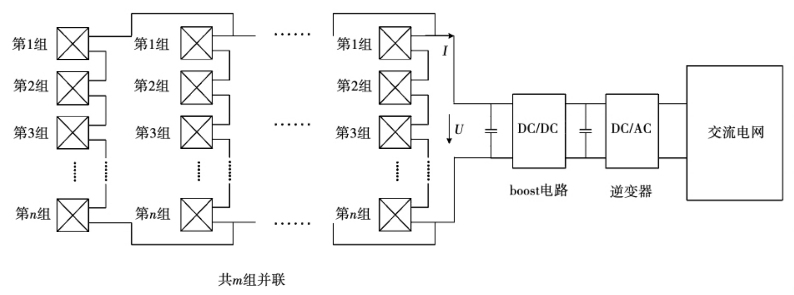
At present, photovoltaic grid connection mostly adopts a two-stage structure, which uses a DC/DC converter to first boost or reduce the DC voltage of the photovoltaic array to meet the requirements of the grid connected solar inverter, while achieving MPPT of the photovoltaic cell array. Then, a DC-AC solar inverter is used to invert the DC power on the DC bus into AC power, achieving the transmission of photovoltaic power generation energy to the grid. Compared to single stage controllers, two-stage controllers are easier to design and parallel expansion of photovoltaic modules is also easier to implement. Figure 1 provides a schematic diagram of this structure.
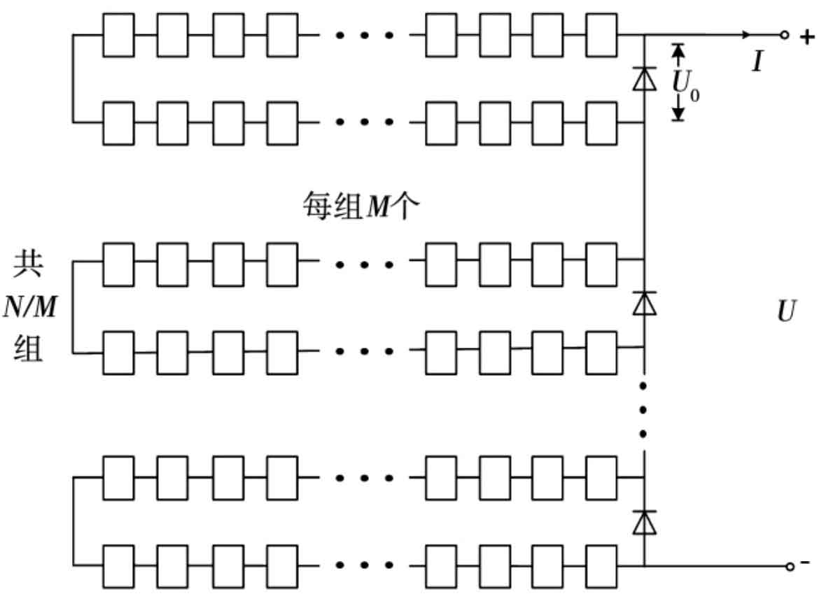
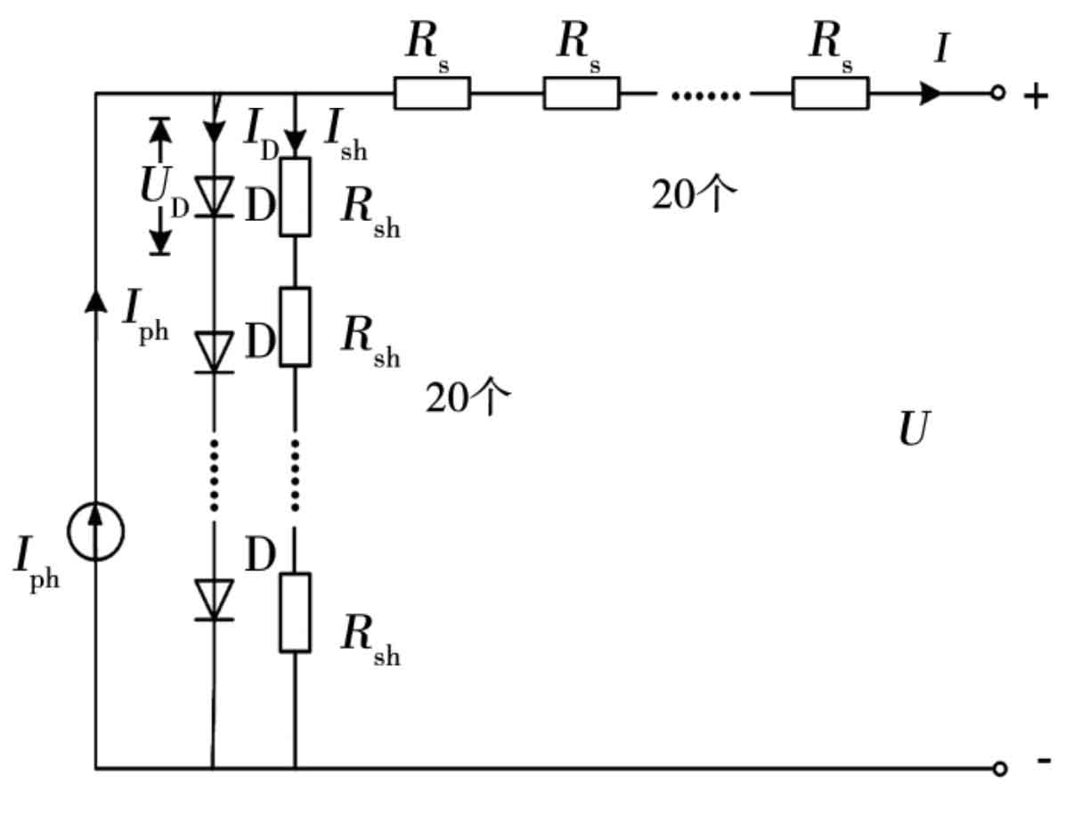
In Figure 1, the photovoltaic array is composed of m * n photovoltaic modules in series and parallel, each consisting of n photovoltaic modules in series. The entire photovoltaic array has a total of m channels, and each photovoltaic module is composed of N silicon wafer monomers in series. Each M monomer forms a unit, and each unit is connected in parallel with a bypass diode. Bypass diodes can effectively reduce the damage of mismatched batteries. The photovoltaic array is connected to the boost circuit as a whole, and then connected to the AC power grid through a solar inverter. Figure 2 shows a schematic diagram of one of the component boards. Figure 3 shows the equivalent circuit diagram of one of the units.
2. Mathematical model of photovoltaic array considering mismatch
2.1 Five parameter model of photovoltaic cells
Figure 4 shows the commonly used single diode equivalent circuit for photovoltaic cells.
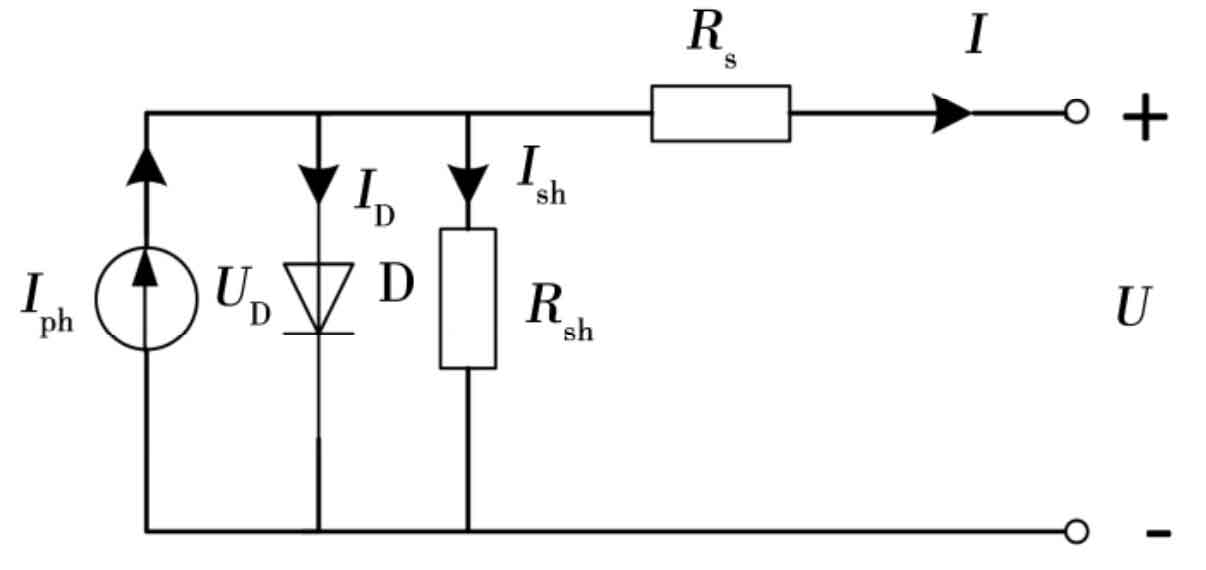
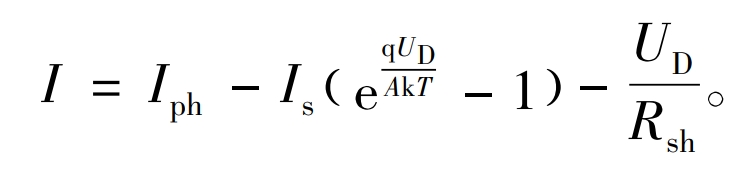
The 5-parameter model expression corresponding to this equivalent circuit is:
In the formula, q is the constant electronic charge, which is 1.602 × 10⁻¹⁹ C; K is the Boltzmann constant, which is 1.381 × 10⁻²³ J/K; A is the fitting coefficient of diode characteristics, which is a variable with a value between 1 and 2. The formula can be regarded as an equation with 5 undetermined parameters, namely Iph, Rsh, q/AkT, Is, Rs. Iph is the photogenerated current, Is is the equivalent diode saturation current, Rsh is the equivalent parallel resistance, and Rs is the equivalent series resistance.
2.2 Improved 5-parameter model for photovoltaic panels considering mismatched parameters
Due to the fact that the current and output voltage of each path in the photovoltaic array can be periodically read by the device, the equations for the output voltage and current of each path are derived first.
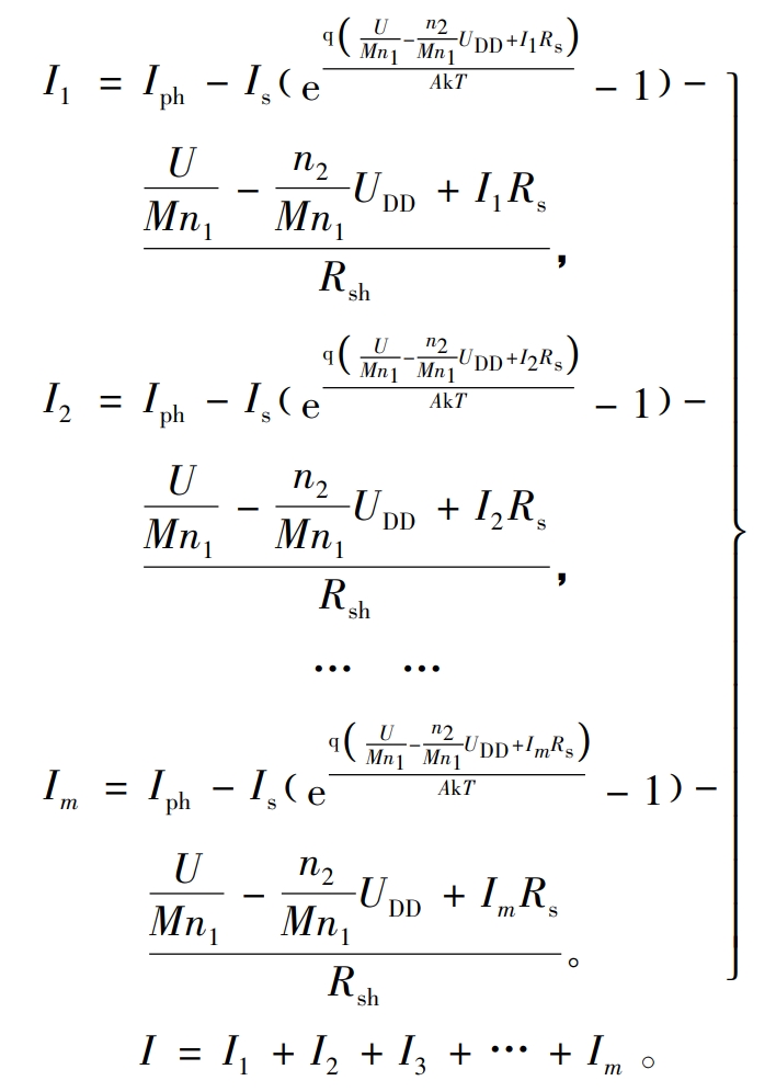
Considering mismatch, for one of the channels, there are a total of n photovoltaic modules, each with N/M units. When any single unit in each unit is obscured, the entire unit will be bypassed by diodes. Assuming that all components in this path component add up to n1 units that are not obscured and n2 units that are obscured, then n1+n2=n * N/M, where n, N, and M are known quantities, the masking reaction amount n2 is introduced. The equivalent diode voltage of each individual cell of an unshielded unit is:
The U-I relationship of one component considering masking is:
2.3 Equivalent mathematical model of photovoltaic array
As shown in Figure 1, for a photovoltaic array containing m channels, the relationship between the output voltage and current of each series group satisfies the formula. The total output voltage of the photovoltaic array is the output voltage of each circuit. The relationship between the total voltage and each sub current, as well as the relationship between the total current and each sub current, can be expressed as:
3. Maximum power point tracking method
3.1 Traditional MPPT method
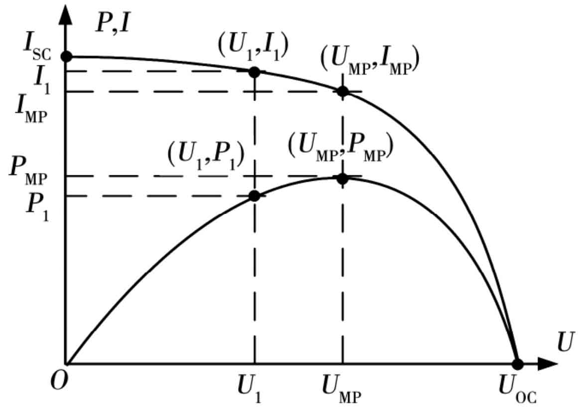
Figure 5 shows the I-U and P-U curves of the photovoltaic array without mismatch. When the lighting and temperature are determined, the working curve of the photovoltaic array is determined. As the voltage increases, the current gradually decreases, and the output power first increases and then decreases. The peak point of the P-U curve is the maximum power point.
The tracking process of the existing MPPT method is shown in Figure 6. Curve L1 represents the front P-U curve, while curve L2 represents the P-U curve where masking occurs. After MPPT, the photovoltaic array operates at point A. But at this point, if masking causes array mismatch or external environmental conditions change, it will cause a change in the P-U curve. Assuming the temperature is constant and the light changes, as the effect of light on UOC is minimal, assuming it remains unchanged, the P-U curve becomes L2. The operating point may have jumped from point A to point C, point D, or other points. If it jumps to point D, the MPPT controller will give a small disturbance to the circuit, and the operating point may move up or down. The choice of direction is blind, and the next direction is determined by observing the changes in the reference quantity, and the disturbance will be perturbed step by step to the new MPP.
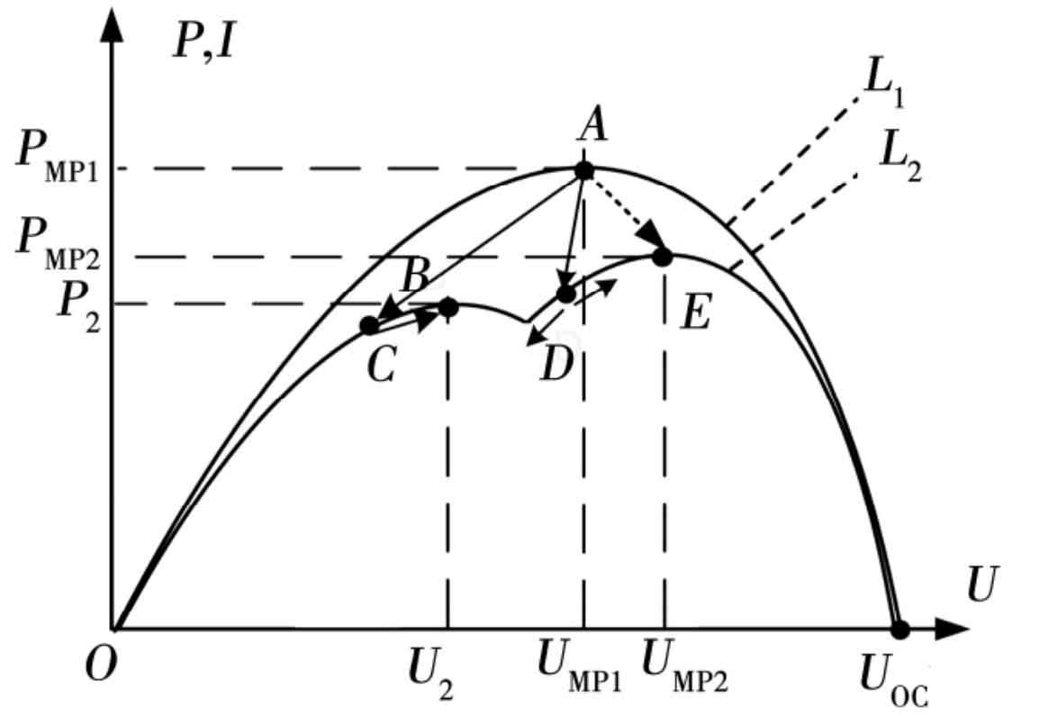
But if the operating point jumps from point A to point C, due to multimodality, the point tracked by the perturbation method is the local maximum power point B, and the array does not output maximum power.
3.2 Determination of mathematical model parameters
Manufacturers generally only provide open circuit voltage UOC, short circuit current ISC, voltage UMP, and current IMP values at the maximum power point under standard operating conditions (irradiance of 1000 W/m ^ 2, battery operating temperature of 25 ℃ (298 K)). The simplified model for engineering applications utilizes these four parameters and makes corrections that take into account changes in temperature and irradiance, which are often limited to measurement errors in actual irradiance and temperature; Most 5-parameter models also use this method for parameter identification, which is actually difficult to implement. The correction formula for Iph, Rsh, Is, and Rs under different illuminances and irradiances is:
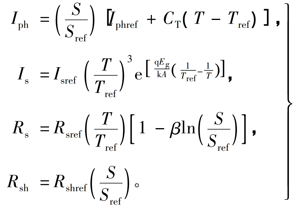
In the formula: Iphref is the photogenerated current under standard operating conditions, A; S is the real-time irradiance, Sref is the irradiance under standard conditions, W/m ^ 2; CT is the temperature coefficient that can be provided by the manufacturer, A/K; Iref is the diode saturation current under standard conditions, A; T is the real-time temperature, Tref is the temperature under standard conditions, K; Eg is the bandgap width, eV, depending on the material of the photovoltaic cell; β = 0.217, the calculation shows that the change in irradiance is not significant for Rs.
Consider the U-I relationship of each series group in the formula as an equation with 6 undetermined parameters, namely Iph, Rsh, q/AkT, Is, Rs, and n2. According to the formula analysis, the influence of temperature and irradiance changes in a short period of time on the parameters can be ignored and can be regarded as fixed values. This set of parameters determines a U-I curve accordingly. By adjusting the external circuit, different operating points on this curve can be obtained.
For one of the series component groups, by adjusting the working state of the external circuit 6 times, measure 6 sets of (U, Ii) values, namely: (U1, Ii1), (U2, Ii2), (U3, Ii3), (U4, Ii4), (U5, Ii5), (U6, Ii6), and substitute them into the formula to obtain 6 equations about the 6 parameters, and then obtain the equations about the 6 parameters. By iterating through the Newton method, the parameters Iph, Rsh, q/AkT, Is, Rs, and the masking situation n2 at the entire point can be determined, thereby determining the U-Ii relationship of the component of the path. This real-time U-I relationship takes into account the mismatch situation, as well as the aging and attenuation of the battery, which matches the current operating curve of the battery. The initial iteration value can select the solution from the previous iteration, which can greatly reduce the number of iterations and ensure the feasibility of the iteration.
3.3 Using Lagrange multiplier method to track maximum power
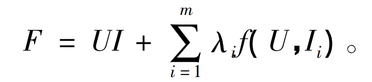
Using the Lagrange multiplier method, record the formula as:
The objective function is:
When P=UI reaches its maximum value, the optimization condition is met:
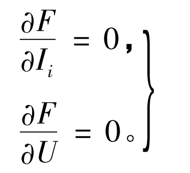
The specific expression is:
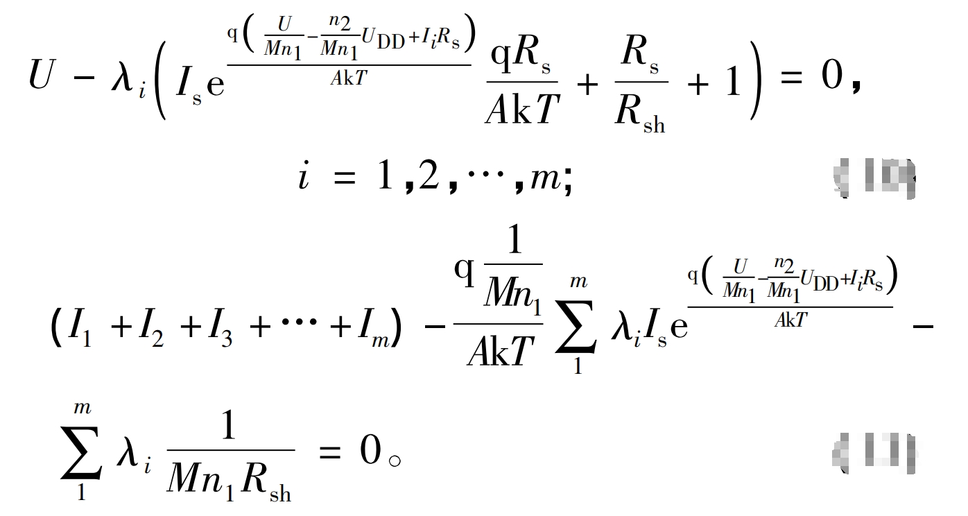
Adding the m formulas of the formula yields:
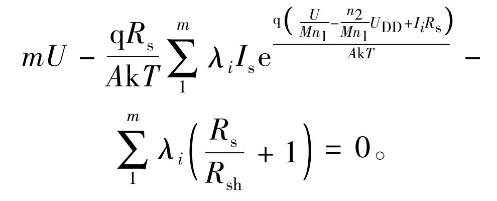
Thus, the formula can be simplified to obtain:
Add m U-Ii equations of the formula to obtain the equations containing (U, I1, I2,…, Im, λ 1, λ 2, λ The zero point function of the 2m+1 unknown equation is:
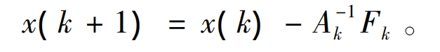
Using the Newton method for iterative calculation, the Jacobian matrix is:
Expanding and substituting the above equation can obtain the Jacobian matrix as:
The iterative formula is:
In the case of local shadows, the P-U curve has multimodality, and the iterative method may converge to the local “pseudo maximum”. For the m group parallel system in Figure 1, there may be at most m+1 peak. When solving, m+1 initial value can be set, and the maximum power points UMP and IMP=I1+I2+…+Im can be obtained through iterative comparison.
Through the disturbance circuit, the data collector collects 6 sets of voltage and current data for operation. The parameter identification module can output the values of 5 parameters for each component and the values of mismatch reflection parameter n2. Then, through the MPPT strategy above, the output voltage and current of the photovoltaic array corresponding to the maximum power point can be output.
By equating the power before and after the DC/DC circuit, the relationship between the system terminal voltage and current and the duty cycle can be obtained. After calculating the I-U value corresponding to the maximum power point, the corresponding duty cycle can be obtained. Adjusting the duty cycle can directly jump the working point to the vicinity of the maximum power point.
4. Actual measurement verification
The experimental data is sourced from the photovoltaic system of the smart grid building at Shanghai Jiao Tong University. Take the measured data of six photovoltaic panels for verification. Each route is composed of 20 component boards connected in series. During the experiment, in order to simulate local cloud shading, the third route is partially masked, so that 4 of the boards are affected by the “cloud shadow” and the output power is 0. Each circuit is connected in parallel with the same voltage. Table 1 provides the voltage and current data of each series component.
| Number | U/V | I1 /A | I2 /A | I3 /A | I4 /A | I5 /A | I6 /A |
| 1 | 284.83 | 6.832 | 5.284 | 6.226 | 6.325 | 5.668 | 5.919 |
| 2 | 362.72 | 6.829 | 5.271 | 6.152 | 6.315 | 5.623 | 5.911 |
| 3 | 449.91 | 6.800 | 5.195 | 5.523 | 6.257 | 5.372 | 5.788 |
| 4 | 475.32 | 6.741 | 5.132 | 4.956 | 6.211 | 5.184 | 5.695 |
| 5 | 520.34 | 6.749 | 4.911 | 3.113 | 6.012 | 4.610 | 5.371 |
| 6 | 554.22 | 6.664 | 4.583 | 0.888 | 5.721 | 3.919 | 4.901 |
Perform parameter identification on each path, taking the initial values as [Iph, Is,/AkT, Rs, Rsh, n]=[7, 0.000 004, 25, 0.000 4, 8 000, 0], all in international units. The values of each parameter are shown in Table 2.
| Routes | Iph /A | Is /μA | q /AkT | Rs /mΩ | Rsh /Ω | n^2 |
| 1 | 6.8324 | 1.2342 | 25.234 | 10.3243 | 83724 | 0.103 |
| 2 | 5.2873 | 2.3425 | 24.988 | 9.3985 | 32452 | 0.294 |
| 3 | 6.2357 | 1.9824 | 25.398 | 6.3975 | 39887 | 0.023 |
| 4 | 6.3277 | 2.0234 | 25.023 | 7.3874 | 73626 | 0.234 |
| 5 | 5.6783 | 4.4235 | 25.284 | 12.2984 | 92834 | 0.153 |
| 6 | 5.9234 | 2.9238 | 25.399 | 8.3423 | 38727 | 0.235 |
From the 5 parameter values of each circuit, the voltage current relationship of each circuit can be determined, and the photovoltaic characteristic curve equation can be written. According to the Lagrange multiplier method, the Jacobian matrix of 13 * 13 for the optimization equation of the 6-way system is listed. Based on the iterative formula, the current values of each path at the maximum power point of the total system can be obtained, as shown in MPP1 in Table 3. The actual maximum power point tracked by the centralized solar inverter was measured, as shown in MPP2 in Table 3.
| No. | MPP1 I/A | MPP1 U/V | MPP1 P/W | MPP1 I/A | MPP1 U/V | MPP1 P/W |
| 1 | 6.774 | 428.1 | 2900 | 6.729 | 455.221 | 3063 |
| 2 | 5.438 | 428.1 | 2328 | 5.185 | 455.221 | 2360 |
| 3 | 5.905 | 428.1 | 2528 | 5.529 | 455.221 | 2517 |
| 4 | 6.189 | 428.1 | 2649 | 6.153 | 455.221 | 2801 |
| 5 | 5.478 | 428.1 | 2345 | 5.338 | 455.221 | 2430 |
| 6 | 5.837 | 428.1 | 2499 | 5.771 | 455.221 | 2627 |
According to Table 3, the maximum power calculated by the method described in this article is 16.7 kW, and the maximum power point tracked by the MPPT control strategy of the centralized solar inverter is 16.1 kW. The output power of the fast MPPT method is 3.72% higher than the actual output power of the on-site solar inverter.
5. Conclusion
A mathematical model of photovoltaic array considering mismatch parameters was derived based on the 5-parameter model of photovoltaic cells. The changes of the 5 parameters under different irradiance and temperature combinations were considered, and an MPPT method based on real-time voltage and current data was designed. Each parameter is a real-time parameter that considers the aging and attenuation of photovoltaic cells under real-time conditions. After practical verification, it can be seen that this mathematical method can effectively track near the maximum power point, has a fast tracking speed, and is more effective than the current disturbance observation method.