
In recent years, the rapid development of battery technology has led to lithium-ion batteries becoming a primary energy storage medium due to their high energy density and long lifespan. However, as the application scale of lithium-ion batteries expands, safety incidents occur frequently, raising widespread concern about the safety of these batteries. Overcharging is one of the main triggers for thermal runaway in lithium-ion batteries, leading to safety issues. In this study, we focus on the thermal runaway behavior of energy-type LiFePO4 batteries under overcharging conditions. Our aim is to investigate the characteristics of thermal runaway and its propagation in battery modules, providing insights for safety design and management of LiFePO4 battery systems.
Electric abuse, particularly overcharging, is a critical factor inducing thermal runaway in lithium-ion batteries. Previous studies have explored the thermal runaway mechanisms under various abusive conditions, but most research has concentrated on power batteries for electric vehicles. There is relatively less research on energy-type LiFePO4 batteries, which are commonly used in stationary energy storage systems. This gap motivates our experimental investigation into the overcharging-induced thermal runaway of large-capacity LiFePO4 batteries.
We conducted overcharging experiments on 60Ah prismatic LiFePO4 batteries and battery modules. The positive electrode material is LiFePO4, the negative electrode is graphite, and the electrolyte primarily consists of ethylene carbonate, dimethyl carbonate, and diethyl carbonate. The experiments were performed in an open environment to simulate real-world conditions. We designed two experimental schemes: overcharging single cells at rates of 0.5C, 1C, and 2C, and overcharging battery modules at the same rates. In the module tests, only the outermost cell was overcharged to examine thermal runaway propagation between cells.
The experimental setup included a data logger, video recorder, and DC charger. All batteries were fully charged before testing. The charger’s maximum voltage was set to 35V; upon reaching this voltage, the charger automatically switched from constant current to constant voltage mode. During thermal runaway, charging was manually stopped. To assess the flammability of ejected gases, a pulse igniter was used to spark near the safety valve at a height of 20 cm. Thermocouples were placed on the battery surfaces to monitor temperature, and voltage was recorded throughout the process.
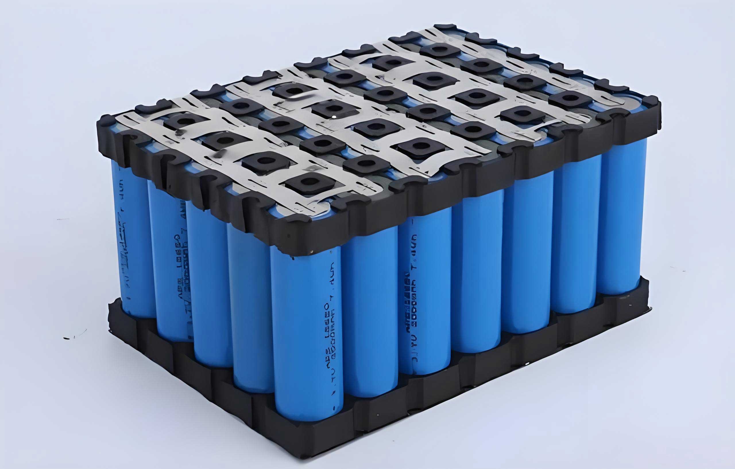
The LiFePO4 battery modules consisted of four fully charged cells arranged without series or parallel connections. In module tests, thermocouples were attached to the center of the largest surface of each cell to capture temperature distributions. This setup allowed us to analyze heat transfer and potential thermal runaway propagation.
Thermal Runaway Behavior of Single LiFePO4 Batteries
Under overcharging at 0.5C, 1C, and 2C rates, all LiFePO4 batteries experienced thermal runaway. During thermal runaway, large amounts of gas were ejected from the safety valve, but no fire was observed initially. To determine the flammability of the ejected gases, we used a pulse igniter to create sparks in the gas plume. Approximately 3 minutes after gas ejection began, the gases ignited, as shown in the image. This indicates that the gases emitted during thermal runaway of LiFePO4 batteries are combustible and can be ignited by external sparks, even if no open flame is present internally.
Based on voltage and surface temperature changes, the overcharging-induced thermal runaway process of LiFePO4 batteries can be divided into four distinct stages. We analyze these stages in detail using data from the 1C overcharging test as a representative example.
Stage I: Slow Rise in Voltage and Temperature. In this stage, the battery voltage slowly increases to a critical point, denoted as $V_1$, while the temperature rises to $T_1$. For the 1C test, $V_1 = 5.59\, \text{V}$ and $T_1 = 84\,^\circ\text{C}$. The gradual increase is due to internal side reactions, such as electrolyte oxidation when voltage exceeds 4.7V and SEI (Solid Electrolyte Interphase) decomposition around 80°C. The heat generated from these reactions, combined with ohmic heating from overcharging, accelerates temperature rise. Gas production from side reactions increases internal pressure until the safety valve ruptures.
The temperature rise during Stage I can be modeled by a heat balance equation:
$$ \frac{dT}{dt} = \frac{Q_{\text{gen}} – Q_{\text{loss}}}{C_p} $$
where $Q_{\text{gen}}$ is the heat generation rate from side reactions and ohmic heating, $Q_{\text{loss}}$ is the heat loss rate to the environment, and $C_p$ is the heat capacity of the LiFePO4 battery. For a LiFePO4 battery, $Q_{\text{gen}}$ increases with temperature due to exothermic reactions.
Stage II: Rapid Rise in Voltage and Temperature. The voltage surges from $V_1$ to the charger’s maximum voltage (35V), while temperature quickly rises to $T_2$. In the 1C test, $T_2 = 103\,^\circ\text{C}$, with an average temperature rise rate of 12.8°C/min. The voltage surge indicates a sharp increase in internal impedance, leading to higher joule heating. This further accelerates side reactions, creating a positive feedback loop. The temperature change can be expressed as:
$$ \Delta T = \int_{t_1}^{t_2} \left( \frac{I^2 R_{\text{int}}}{C_p} + \frac{Q_{\text{side}}}{C_p} \right) dt $$
where $I$ is the charging current, $R_{\text{int}}$ is the internal resistance, and $Q_{\text{side}}$ is the heat from side reactions.
Stage III: Voltage Drop to 0V and Secondary Slow Temperature Rise. When the voltage reaches the set maximum, the charger switches to constant voltage mode, reducing current. The voltage drops to approximately 0V, indicating internal short circuit due to separator failure. Temperature continues to rise slowly from $T_2$ to $T_3$ (127°C in the 1C test). The reduced current decreases joule heating, slowing the temperature rise rate. This stage reflects the degradation of internal structure in the LiFePO4 battery.
Stage IV: Temperature Surge and Decline. Thermal runaway occurs, with temperature rapidly increasing from $T_3$ to a maximum $T_{\text{max}}$ (495°C in the 1C test). Large amounts of combustible gases are ejected, carrying away heat. As internal reactions subside, heat generation falls below heat loss, causing temperature to decline. The peak temperature can be estimated by considering the total energy released:
$$ T_{\text{max}} = T_3 + \frac{E_{\text{release}}}{C_p} $$
where $E_{\text{release}}$ is the energy released from exothermic reactions during thermal runaway of the LiFePO4 battery.
We conducted tests at different overcharging rates to analyze the impact on thermal runaway parameters. The key parameters are summarized in Table 1.
| C-rate | $t_1$ (s) | $t_2$ (s) | $t_3$ (s) | $T_1$ (°C) | $T_2$ (°C) | $T_3$ (°C) | $T_{\text{max}}$ (°C) | $Q_1$ (Ah) | $Q_2$ (Ah) | $Q_3$ (Ah) | $V_1$ (V) |
|---|---|---|---|---|---|---|---|---|---|---|---|
| 0.5C | 3372 | 3550 | 4187 | 96 | 122 | 154 | 503 | 28.1 | 29.6 | 34.9 | 5.18 |
| 1C | 1388 | 1477 | 1636 | 84 | 103 | 127 | 495 | 23.1 | 24.6 | 27.3 | 5.59 |
| 2C | 527 | 605 | 816 | 71 | 100 | 135 | 425 | 17.6 | 20.2 | 27.2 | 5.64 |
From Table 1, as the overcharging rate increases, the times $t_1$, $t_2$, and $t_3$ decrease significantly, indicating a faster progression to thermal runaway. The overcharged electricity $Q_1$, $Q_2$, and $Q_3$ also decrease, suggesting that higher rates lead to more intense polarization and side reactions, reducing the charge needed to trigger each stage. The initial voltage $V_1$ increases with rate due to higher polarization. Notably, $T_{\text{max}}$ decreases at higher rates; for example, at 2C, $T_{\text{max}} = 425\,^\circ\text{C}$ compared to 503°C at 0.5C. This is because high-rate overcharging causes the voltage to reach the maximum quicker, limiting the completeness of internal reactions and thus reducing the total heat release. This highlights the complex thermal behavior of LiFePO4 batteries under abusive conditions.
The temperature evolution during overcharging can be further analyzed using a kinetic model. The rate of side reactions, such as SEI decomposition and electrolyte oxidation, follows an Arrhenius equation:
$$ k = A e^{-E_a / (RT)} $$
where $k$ is the rate constant, $A$ is the pre-exponential factor, $E_a$ is the activation energy, $R$ is the gas constant, and $T$ is temperature. For a LiFePO4 battery, multiple reactions occur simultaneously, contributing to heat generation. The total heat generation rate $Q_{\text{gen}}$ can be expressed as:
$$ Q_{\text{gen}} = I^2 R_{\text{int}} + \sum_i \Delta H_i r_i $$
where $\Delta H_i$ is the enthalpy change and $r_i$ is the rate of reaction $i$. This model helps explain the accelerated temperature rise in Stage II.
Thermal Runaway Propagation in LiFePO4 Battery Modules
We also investigated thermal runaway propagation in battery modules. The module consisted of four LiFePO4 batteries, with only the outermost cell (Cell 1) overcharged. In tests at 0.5C, 1C, and 2C rates, only Cell 1 underwent thermal runaway, ejecting gases. However, at 0.5C and 1C, the adjacent cell (Cell 2) had its safety valve rupture due to heat exposure, while Cells 3 and 4 remained intact. At 2C, all other cells (Cells 2, 3, 4) stayed intact, with no valve rupture. This suggests that higher overcharging rates reduce the thermal impact on neighboring cells due to shorter thermal runaway duration and lower heat release.
Figure 6 shows the voltage and temperature curves for the module under 1C overcharging. Cell 1’s voltage behavior resembles that of single cells, but internal short circuit occurs later at 1929s compared to 1636s in the single test, due to heat dissipation to Cell 2. The other cells maintain constant voltage, indicating no structural damage. Temperature data reveal a gradient: Cell 2’s side near Cell 1 reached 452°C, while the opposite side was at 84.4°C, causing valve rupture only on the heated side. Cells 3 and 4 had temperatures below 60°C, showing minimal heat transfer. This demonstrates that thermal runaway propagation in LiFePO4 battery modules is influenced by heat conduction and cell spacing.
The heat transfer between cells can be described by Fourier’s law:
$$ q = -k \nabla T $$
where $q$ is the heat flux, $k$ is the thermal conductivity, and $\nabla T$ is the temperature gradient. For a LiFePO4 battery module, the heat dissipation depends on the module design and materials. The temperature rise in adjacent cells can be estimated using a lumped capacitance model:
$$ T(t) = T_{\text{env}} + (T_0 – T_{\text{env}}) e^{-t/\tau} + \frac{Q_{\text{input}}}{hA} (1 – e^{-t/\tau}) $$
where $T_{\text{env}}$ is the environment temperature, $T_0$ is the initial temperature, $\tau$ is the time constant, $Q_{\text{input}}$ is the heat input from the runaway cell, $h$ is the heat transfer coefficient, and $A$ is the surface area. This model explains why Cell 2 experienced significant heating while Cells 3 and 4 did not.
Discussion on Safety Implications
The findings have important safety implications for LiFePO4 battery systems. The combustibility of ejected gases means that even if a LiFePO4 battery does not ignite internally, external ignition sources can cause fires. Therefore, battery enclosures should include spark prevention and ventilation systems. The four-stage thermal runaway process provides a framework for early warning systems; monitoring voltage and temperature can help detect anomalies before catastrophic failure.
Moreover, the inverse relationship between overcharging rate and maximum temperature suggests that fast charging might reduce the severity of thermal runaway in LiFePO4 batteries, but it also shortens the time to failure, requiring faster response mechanisms. In module design, thermal barriers or spacing between cells can mitigate propagation, as shown by the temperature gradients. These insights are crucial for developing safer energy storage systems using LiFePO4 batteries.
To further analyze the thermal runaway energy, we can calculate the approximate energy released during Stage IV. Assuming the LiFePO4 battery has a mass $m$ and specific heat capacity $c_p$, the energy required to raise temperature from $T_3$ to $T_{\text{max}}$ is:
$$ E = m c_p (T_{\text{max}} – T_3) $$
For a 60Ah LiFePO4 battery with mass around 1.2 kg and $c_p \approx 1000\, \text{J/kgK}$, the energy release at 1C is:
$$ E \approx 1.2 \times 1000 \times (495 – 127) = 441.6\, \text{kJ} $$
This substantial energy release underscores the hazards of thermal runaway in LiFePO4 batteries.
Conclusion
In this study, we experimentally investigated the thermal runaway behavior of energy-type LiFePO4 batteries under overcharging conditions. Key conclusions are:
- The gases ejected during thermal runaway of LiFePO4 batteries are combustible and can be ignited by external sparks, highlighting a fire risk even without internal ignition.
- The overcharging-induced thermal runaway process for LiFePO4 batteries consists of four stages: slow voltage/temperature rise, rapid voltage/temperature rise, voltage drop to 0V with secondary slow temperature rise, and temperature surge followed by decline. This staging is consistent across different overcharging rates.
- As the overcharging rate increases, the time to trigger thermal runaway in LiFePO4 batteries shortens significantly, while the maximum temperature decreases, indicating reduced thermal effects. This suggests that higher rates may lessen the severity but accelerate the onset of failure.
- In battery modules, thermal runaway propagation is limited to adjacent cells, with heat transfer causing safety valve rupture only in nearby cells at lower rates. At higher rates, propagation is further suppressed due to shorter thermal exposure.
These findings contribute to a better understanding of LiFePO4 battery safety and can inform the design of protection systems for energy storage applications. Future work could involve modeling thermal runaway kinetics and exploring mitigation strategies for LiFePO4 battery packs.