
Solar energy, as an environmentally friendly, safe, and pollution-free new type of energy, is constantly expanding its application fields. Among them, as a typical application of solar vehicles, it has been greatly developed since the second half of the 1970s when road experiments proved its technical feasibility. In recent years, with the maturity of high-capacity battery pack technology, it has become possible to replace traditional fuels with solar energy to provide power security. The solar emergency support power station vehicle, which combines large-scale solar power generation (storage) systems with heavy-duty vehicles, has high power, good stability, and few constraints. These performance advantages make it have broad application prospects in emergency support, disaster relief, emergencies, natural disasters, forest fire prevention, field operations, military activities, and other fields. However, solar powered vehicles also have their own technological limitations. In order to ensure the power supply of AC loads, inverters, as important components of photovoltaic power generation systems, their electronic switches and PWM technology can cause certain interference to the electromagnetic environment. Therefore, for some work scenarios with specific requirements for the electromagnetic environment, their electromagnetic compatibility must be considered. To further understand the impact of this interference, this article takes the solar emergency support power station vehicle as the test object, collects and compares the electromagnetic spectrum data of its working and shutdown states, and provides a reference value for electromagnetic compatibility evaluation.
1. Solar photovoltaic power generation
Solar power generation mainly utilizes the photovoltaic effect. The so-called photovoltaic effect refers to the phenomenon where when sunlight shines on a semiconductor, it produces pairs of electrons and holes, which accumulate opposite charges under the action of an electrostatic field, resulting in a potential difference at both ends of the battery.

The solar photovoltaic power generation system, as a device that directly converts solar energy into electricity using solar cells, mainly consists of solar panels (photovoltaic arrays), controllers, battery packs, and inverters, as shown in Figure 1. Solar panels serve as a receiving device for light, used to directly convert solar energy into electrical energy; The controller is mainly used to protect the normal operation of batteries and circuits with reasonable charging and discharging control strategies; A battery pack is used to store the electrical energy generated by solar panels for use by subsequent loads; The function of the inverter is to convert the low-voltage direct current provided by the solar panel and battery into alternating current, which is an indispensable component for supplying power to AC loads. The working characteristics of inverters themselves are often the main causes of high-order harmonic noise and high-frequency electromagnetic interference in photovoltaic power generation systems.
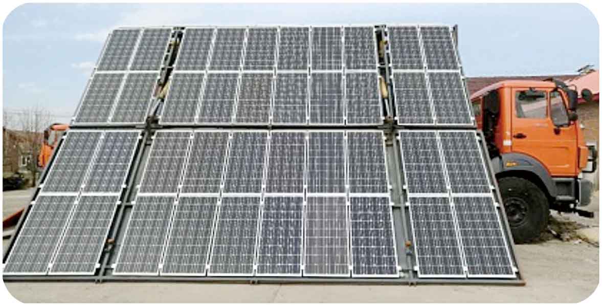
According to different application scenarios, solar photovoltaic power generation systems can be divided into three types: independent, grid connected, and hybrid. The solar vehicle tested and studied in this article adopts the independent photovoltaic power generation mode, which is mostly used for navigation, alarm, wireless communication emergency support, etc. As shown in Figure 2, this is a physical image of the solar powered vehicle used in this test. The battery pack used is the Huafu CN-600 lead-acid battery pack for energy storage, which can provide uninterrupted power supply for 24 hours. During the task, the solar panel can be quickly unfolded and folded, making it easy to operate and use. The specific technical parameter indicators are detailed in Table 1.
| Total installed power | 11kWp | Energy storage capacity | > 55kW |
| Standard output voltage | AC-220V | Battery capacity | 1200Ah (system voltage is 110V) |
| Power supply level | 10kW~30kW | Operating temperature | -40 ℃+60 ℃ |
| Wind resistance level | Level 5 | Dynamic system | Hydraulic+electric |
| Vehicle size | 6.4×2.5×4.15(/m) | Total mass | 12000kg |
| Power plant deployment time | ≤ 6min | Collapse time | ≤ 10min |
2. Electromagnetic interference in photovoltaic systems
According to the definition given by the International Electrotechnical Commission (IEC), electromagnetic compatibility refers to the ability of a device to perform its functions satisfactorily in an electromagnetic environment without causing unacceptable interference to the environment (including other devices). The electromagnetic interference of photovoltaic power generation systems is mainly caused by the use of power electronic switching devices and PWM technology in the inverter circuit, which directly leads to a large rate of voltage change over time and a large absolute value of dv/dt. This large rate of change here is equivalent to the emission source of electromagnetic waves. According to the differences in the propagation pathways of electromagnetic interference, it can be divided into two types: conducted interference and radiated interference. The so-called conducted interference refers to the coupling of interference signals from interference sources to sensitive devices through directly connected circuits; The so-called radiation interference refers to the propagation of interference signals in the form of electromagnetic waves, coupled to the interfered circuit. The electromagnetic compatibility of solar powered vehicles studied in this article is tested and evaluated from the perspective of their radiation interference. The radiation interference mechanism of photovoltaic power generation can be summarized as a complex antenna system composed of silver wires that absorb electrons in solar cells, brackets and wires of photovoltaic arrays. High order harmonics generated by power electronic switches such as inverters can form electromagnetic radiation in the surrounding area through the antenna of photovoltaic arrays, thereby causing radiation interference to other electronic devices.
3. Test evaluation
The test aims to collect electromagnetic spectrum data of solar powered vehicles in both working and shutdown states. Through monitoring and comparison software, the agreement of the radio noise level envelope curves of the two data samples is compared to evaluate the electromagnetic compatibility of solar powered vehicles during operation.

This test uses PR100 as the signal receiver, and the data collected by the test antenna is processed and transmitted to a laptop with professional monitoring and comparison functions to obtain a comparison chart of the level envelope curve of the noise signal sample. At the same time, use a spectrophotometer to mark the same frequency band and record the level values for quantitative verification (see Figure 3).
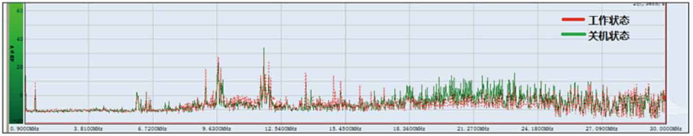
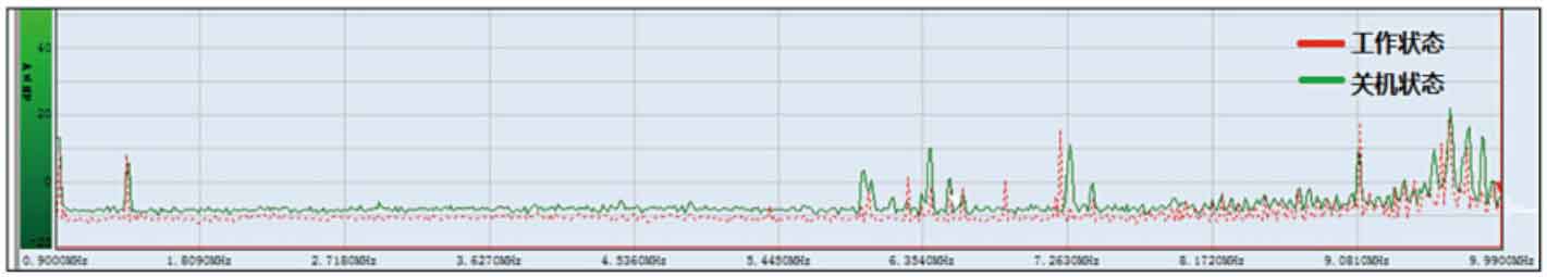
In the test, sample data in the short wave frequency band (9kHz~30MHz) was first collected, as shown in Figure 4. From the graph, it can be seen that the signal level envelope curves under the two working conditions are basically the same, which means that the impact of solar powered vehicles on the surrounding electromagnetic environment is not significant in the short wave frequency band during operation. In order to make this comparison more obvious, the comparison frequency band was reduced in the test to achieve better monitoring results, as shown in Figure 5. The comparison frequency band was adjusted to 9kHz~10MHz, from which it can be more clearly seen that there is basically no difference in the electromagnetic spectrum data between the two situations. Therefore, it can be concluded that for the tested solar powered vehicle, it has little effect on the surrounding electromagnetic environment in the short wave frequency range.
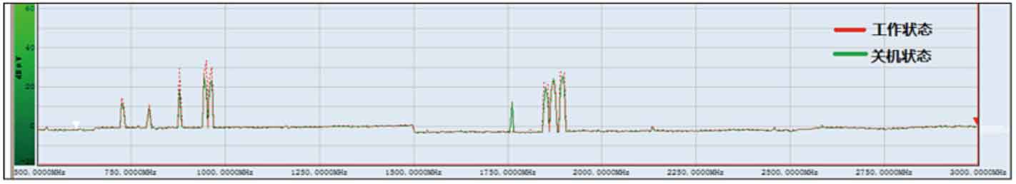
For the electromagnetic compatibility of solar powered vehicles, in most cases, the ultra short wave frequency band, namely the 30MHz to 3000MHz frequency band, is more concerning because most radio services are assigned to this frequency band, and some interference investigation and activity support tasks are also focused on this frequency band. Therefore, a key comparison was also made in the testing of this frequency band, as shown in Figure 6. Taking 500MHz to 3000MHz as an example, it can be seen that the spectrum data curves collected under the two conditions are basically consistent, similar to the short band. From the test comparison results, it can be seen that in the ultra short wave frequency band, the electromagnetic compatibility of the tested solar vehicle is still good, and there is not much electromagnetic interference to the surrounding environment.
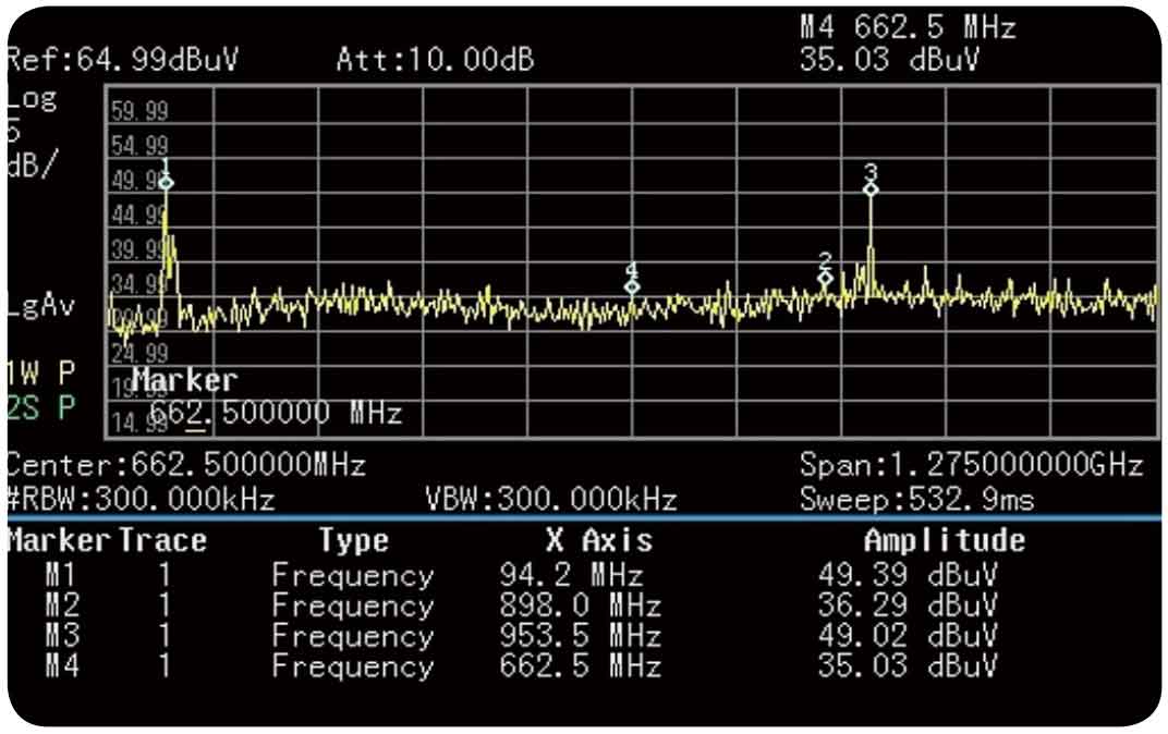
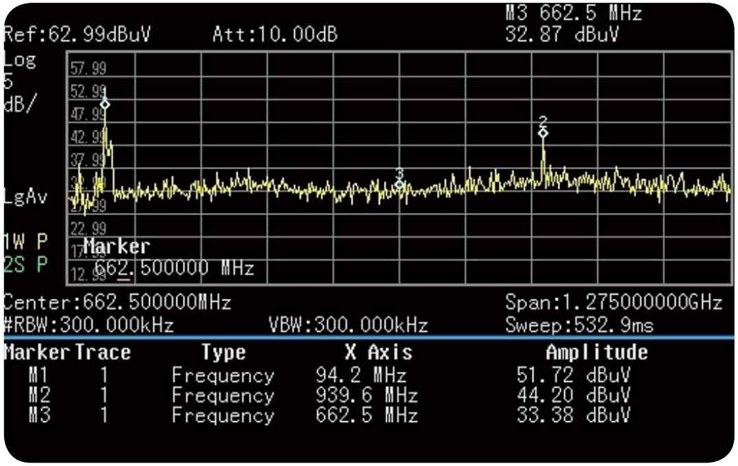
Based on the above comparative analysis results, it can be concluded that for the tested solar emergency power supply vehicle, it has good electromagnetic compatibility in the frequency range of 9kHz to 3000MHz. However, the accuracy of the methods and instrument equipment used in the test did not show that the solar vehicle will have a significant impact on the surrounding electromagnetic environment during operation. Figures 7 and 8 show the frequency band scanning data of solar powered vehicles in the 25MHz to 1300MHz frequency band under different operating conditions, respectively, monitored using the N9344C spectrophotometer. From the sampled frequency point level values, it can be seen that the two situations are basically consistent, which once again verifies the test results of the monitoring comparison above.