Due to the difficulty in obtaining a relatively simple expression for the voltage current relationship from the given solar cell array characteristic equation, in practice, the characteristic curves of solar cells under different environmental conditions are often obtained based on fitting parameters and actual parameters. Figure 1 shows the characteristic curves of solar cells under different environmental conditions.
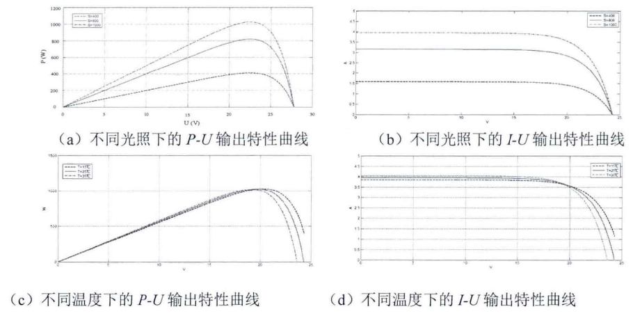
From the graph, it can be seen that while keeping the environmental conditions constant, the output power of the solar cell slowly increases with the increase of electricity output, and rapidly decreases when reaching a certain value. The output current of solar cells always remains near the short-circuit current, and as the voltage continues to rise, the output current rapidly decreases.
Due to the non-linear variation of solar cell parameters with environmental changes, it is often necessary to build solar cell models based on actual engineering situations, in order to establish more simplified solar cell models. Based on the electronic components in Figure 2 and the short-circuit current, open circuit voltage, maximum power voltage, and maximum power current provided by the manufacturer under standard conditions, a mathematical expression is constructed to simulate the I-U curve.
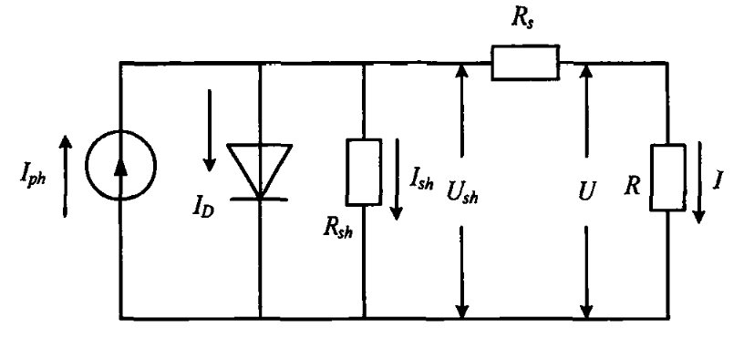
By analyzing the I-U curve and equivalent circuit diagram under certain operating conditions, the output characteristic equation of the solar cell can be derived:
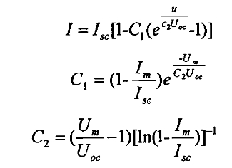
In the formula, Isc and Uoc are the short-circuit current and open circuit voltage of the solar cell;
Im and Um are the maximum power current and voltage.
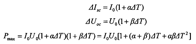
The above equation represents the simulation model of solar cells under specific conditions. In order to obtain the simulation model in any environment, environmental correction is required. In order to perform environmental correction, the current temperature coefficient is introduced Δ Isc, voltage temperature coefficient Δ Uoc, power temperature coefficient Pmax, and current and voltage correction values dI and dU.
Ignoring the square term yields:
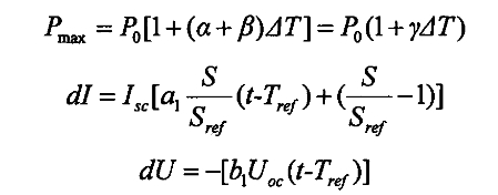
Among them, Sref and Tref are the light intensity and temperature under standard environment (the standard light intensity and temperature have been provided earlier). S. T represents the actual light intensity and temperature. α 1. B1 is the compensation coefficient for lighting and temperature. Derive the corrected output characteristic equation based on the above equation.
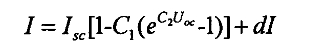
The seed delivery model can obtain the output characteristics of solar cells in different environments, but there are also shortcomings, that is, it does not provide the basic performance parameters of solar cells in different environments, so it has certain limitations in application.
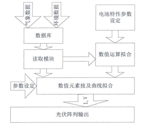
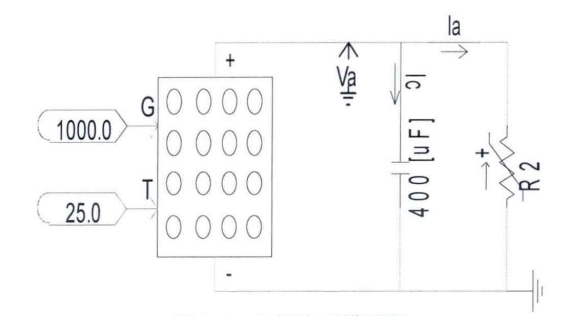
Figures 3 and 4 respectively show the schematic and model diagrams of the photovoltaic array model constructed in PSCAD.