
As a researcher focused on renewable energy integration, I have extensively studied the challenges faced by photovoltaic (PV) systems during grid disturbances. The on-grid inverter serves as a critical interface between PV arrays and the utility grid, and its performance under fault conditions is paramount for grid stability. Among various topologies, the three-phase cascaded H-bridge (CHB) on-grid inverter is particularly advantageous for medium- to high-voltage applications due to its modular structure and ability to generate multilevel output voltages, thereby improving power quality. However, during low-voltage ride-through (LVRT) events, especially under asymmetric faults like phase-to-phase short circuits, this on-grid inverter topology encounters significant issues with active power backflow. This can lead to unbalanced operation points and potential system shutdown, violating grid codes. In this article, I present a harmonic compensation strategy to enhance the LVRT capability of CHB on-grid inverters, addressing these limitations through detailed theoretical analysis, mathematical formulations, tabular comparisons, and experimental validation.
The importance of on-grid inverters in PV systems cannot be overstated. They convert DC power from solar panels into AC power synchronized with the grid, ensuring efficient energy transfer. The CHB on-grid inverter, composed of multiple H-bridge modules per phase, offers scalability and reduced harmonic distortion. However, during LVRT, grid standards require the on-grid inverter to remain connected and inject reactive current to support grid voltage. For asymmetric faults, negative-sequence voltages interact with positive-sequence currents, causing active power to flow back into the inverter. In isolated CHB on-grid inverters with separate DC links per phase, this backflow can elevate DC bus voltages, triggering protection mechanisms and disconnection. Thus, improving the LVRT performance of on-grid inverters is essential for reliable grid integration.
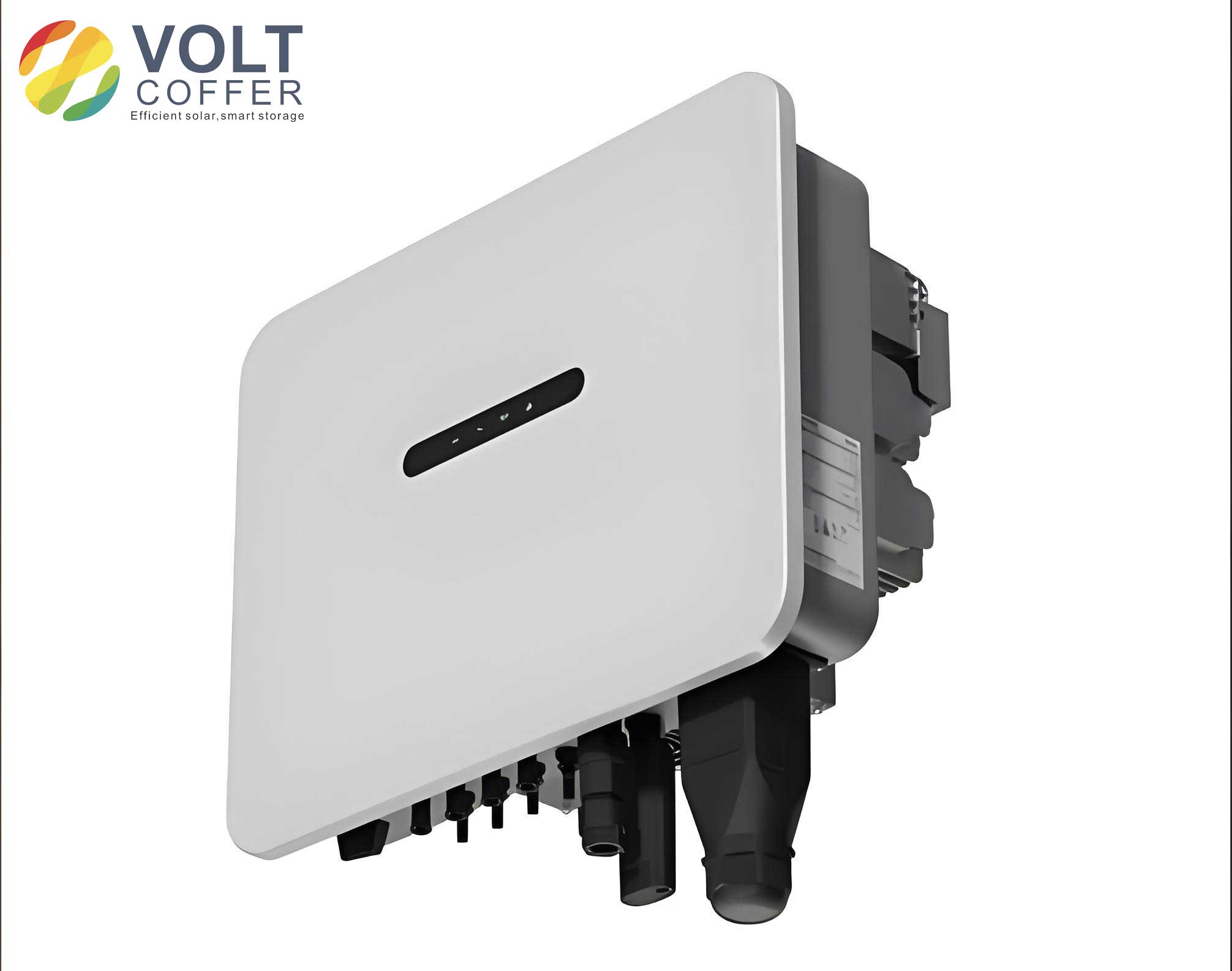
To understand the problem, consider a three-phase CHB on-grid inverter under a phase-to-phase short-circuit fault, such as between phases b and c. The grid voltages become unbalanced, leading to negative-sequence components. The active power per phase for an on-grid inverter can be expressed in terms of symmetrical components. Let $$u_{g}^{p}$$ and $$u_{g}^{n}$$ represent the positive- and negative-sequence grid voltages, respectively, and $$i_{g}^{p}$$ and $$i_{g}^{n}$$ the corresponding currents. The instantaneous active power for phase x (where x = a, b, c) is given by:
$$p_x = u_{gx} \cdot i_{gx}$$
In the dq-frame, the total active power P and reactive power Q for an on-grid inverter are:
$$P = \frac{3}{2}(u_{d}^{p} i_{d}^{p} + u_{q}^{p} i_{q}^{p} + u_{d}^{n} i_{d}^{n} + u_{q}^{n} i_{q}^{n})$$
$$Q = \frac{3}{2}(u_{q}^{p} i_{d}^{p} – u_{d}^{p} i_{q}^{p} + u_{q}^{n} i_{d}^{n} – u_{d}^{n} i_{q}^{n})$$
During LVRT, grid codes mandate the injection of reactive current. For asymmetric faults, the positive-sequence reactive current $$i_{q}^{p}$$ is determined by voltage dip depth D and rated current $$I_{gN}$$:
$$i_{q}^{p} = \min\{2(0.9 – D)I_{gN}, 0.4 I_{gN}\}, \quad D < 0.9$$
The positive-sequence active current $$i_{d}^{p}$$ is limited by the available PV power. Define $$R_P = P_T / P_N$$, where $$P_T$$ is the actual PV output power and $$P_N$$ is the rated power. Then:
$$i_{d}^{p} = \frac{2 R_P I_{gN}}{D + 1}$$
Under phase-to-phase faults, the negative-sequence voltage $$u_{g}^{n}$$ causes active power backflow when $$i_{d}^{p}$$ is low. Existing methods, such as the Adaptive Zero-Sequence Voltage Compensation Strategy (AZSVCS), mitigate this by injecting a zero-sequence voltage $$u_0$$ to redistribute active power among phases. For an on-grid inverter, the compensation voltage is:
$$u_0 = -f(D, R_P) U_N \cos(\omega t + \phi + 2\pi/3)$$
where $$f(D, R_P)$$ is an adaptive coefficient ranging from 0 to 1. While AZSVCS reduces backflow, it increases the modulation voltage amplitude in non-fault phases, risking over-modulation. Another approach, the Positive-Negative Sequence Maximum-Minimum Harmonic Zero-Sequence Voltage Injection Strategy (PNSMMHZSVIS), combines AZSVCS with harmonic voltage injection to further shrink the backflow region. However, it still leaves substantial backflow areas under severe dips and low power output.
To address these limitations, I propose a harmonic compensation strategy that enhances the LVRT performance of CHB on-grid inverters. The key idea is to extend the modulation voltage of the non-fault phase into three symmetric voltages, compute their maximum and minimum harmonic components, and use these as zero-sequence compensation. This reduces modulation indices and expands the stable operating region. For a phase-to-phase fault between b and c, phase a is the non-fault phase. After applying AZSVCS, the modulation voltage for phase a is:
$$u_{ca}^* = U_{gN} B \cos(\omega t – \alpha)$$
where $$B = \sqrt{1 + \left[\frac{f(D, R_P)(1-D)}{2}\right]^2 – f(D, R_P)(1-D)\cos 2\phi}$$ and $$\alpha = \arccos\left(\frac{2 – f(D, R_P)(1-D)\cos 2\phi}{\sqrt{4 + [f(D, R_P)(1-D)]^2 – 4 f(D, R_P)(1-D)\cos 2\phi}}\right)$$. To lower the amplitude of $$u_{ca}^*$$, I extend it into three symmetric voltages:
$$u_{ca1}^* = U_{gN} B \cos(\omega t – \alpha)$$
$$u_{ca2}^* = U_{gN} B \cos(\omega t – 2\pi/3 – \alpha)$$
$$u_{ca3}^* = U_{gN} B \cos(\omega t + 2\pi/3 – \alpha)$$
The harmonic zero-sequence voltage $$u_H$$ is then calculated as:
$$u_H = \frac{\max(u_{ca1}^*, u_{ca2}^*, u_{ca3}^*) + \min(u_{ca1}^*, u_{ca2}^*, u_{ca3}^*)}{2}$$
Finally, the total modulation voltages for the on-grid inverter become:
$$u_{ca1}^{**} = u_{ca}^* + u_H$$
$$u_{cb1}^{**} = u_{cb}^* + u_H$$
$$u_{cc1}^{**} = u_{cc}^* + u_H$$
This harmonic injection ensures that the modulation indices are reduced, minimizing over-modulation risk while suppressing active power backflow. The effectiveness of this strategy can be analyzed by comparing the backflow regions for different control methods. Define the modulation index $$S_T = U_{ca1}^{**} / U_{gN}$$, where $$U_{ca1}^{**}$$ is the peak modulation voltage. For stable operation, $$S_T \leq 1$$. The backflow region is the area in the $$R_P$$-D plane where active power backflow occurs. I computed these regions for AZSVCS, PNSMMHZSVIS, and the proposed harmonic compensation strategy, as summarized in Table 1.
| Control Strategy | Backflow Region Area (normalized) | Reduction Compared to AZSVCS | Key Features |
|---|---|---|---|
| AZSVCS | 0.04288 | 0% | Base adaptive zero-sequence injection |
| PNSMMHZSVIS | 0.01700 | 60.4% | Combines harmonic injection with sequence separation |
| Proposed Harmonic Compensation | 0.00956 | 77.7% | Extends non-fault phase voltage and uses max-min harmonic voltage |
The mathematical derivation shows that the proposed strategy significantly shrinks the backflow area. For instance, at $$D = 0.2$$ and $$R_P = 0.06$$, the modulation index $$S_T$$ is reduced from 0.95 with AZSVCS to 0.87 with the harmonic compensation, allowing the on-grid inverter to operate without over-modulation. This is crucial for maintaining grid connection during faults. The improvement stems from the additional degrees of freedom provided by harmonic voltage injection, which reshapes the modulation waveforms without affecting active power balance.
To validate the strategy, I implemented a low-voltage prototype of a three-phase CHB on-grid inverter. Each phase consisted of two three-level LLC converters and eight H-bridge modules, with a rated power of 3.6 kW. The grid simulator provided a 120 V, 50 Hz supply, and the PV simulator emulated solar input. The control system used digital signal processors to execute the proposed algorithm. During experiments, a phase-to-phase short-circuit fault between b and c was applied with $$D = 0.2$$ and $$R_P = 0.06$$. The reference currents were set to $$i_{d}^{p} = 2 \, \text{A}$$ and $$i_{q}^{p} = 8 \, \text{A}$$, with an adaptive coefficient $$f(D, R_P) = 0.65$$. The DC bus voltages remained stable at 17.5 V, indicating no active power backflow. Moreover, the modulation voltages showed no over-modulation, and the grid currents exhibited fast dynamic response with a recovery time of 104.7 ms upon fault clearance, meeting LVRT requirements.
The experimental results confirm the theoretical advantages. Table 2 lists key performance metrics for the on-grid inverter under the tested conditions.
| Parameter | Value | Comments |
|---|---|---|
| DC Bus Voltage Stability | ±0.2 V variation | No significant backflow-induced rise |
| Modulation Index (S_T) | 0.87 | Below unity, ensuring no over-modulation |
| Grid Current THD | < 5% | Within grid standards |
| LVRT Response Time | 104.7 ms | Complies with grid code mandates |
| Active Power Backflow | Negligible | Verified via power analyzer measurements |
These findings demonstrate that the harmonic compensation strategy enhances the robustness of on-grid inverters during asymmetrical faults. The on-grid inverter maintains stable operation even under deep voltage dips and low power output, expanding its LVRT capability. This is particularly important for large-scale PV farms where grid faults are common, and the on-grid inverter must support grid stability.
Further analysis involves the impact of parameter variations. The adaptive coefficient $$f(D, R_P)$$ plays a critical role in optimizing performance. I derived an analytical expression for $$f(D, R_P)$$ based on power balance constraints. For an on-grid inverter, the condition to avoid backflow is that the active power per phase $$P_x > 0$$. Using symmetrical components, this leads to:
$$f(D, R_P) = \begin{cases}
0 & \text{if } i_{d}^{p} \geq \frac{\sqrt{3}(1-D)i_{q}^{p}}{3D+1} \\
1 – \frac{2(D+1)i_{d}^{p}}{(1-D)(i_{d}^{p} + \sqrt{3}i_{q}^{p})} & \text{otherwise}
\end{cases}$$
This ensures minimal zero-sequence injection while preventing backflow. The harmonic compensation then builds upon this by adding $$u_H$$, which further reduces modulation stresses. The total compensation voltage $$u_{comp} = u_0 + u_H$$ is purely AC and does not affect the average active power transfer, making it suitable for on-grid inverter applications.
In comparison to other topologies, the CHB on-grid inverter benefits greatly from this strategy due to its modular nature. However, the principles can be adapted to other multilevel on-grid inverters, such as modular multilevel converters (MMCs). The key is to manipulate zero-sequence voltages to control power distribution among phases. For future work, integrating this strategy with model predictive control could further improve dynamic response. Additionally, the on-grid inverter’s interaction with grid impedance should be studied to ensure stability under weak grid conditions.
In conclusion, the proposed harmonic compensation strategy effectively addresses active power backflow in CHB on-grid inverters during LVRT, especially for phase-to-phase short-circuit faults. By extending the non-fault phase modulation voltage into symmetric components and injecting calculated harmonic zero-sequence voltages, the method reduces modulation indices and shrinks the backflow region significantly. Experimental results on a low-power prototype confirm the feasibility and superiority over existing methods. This advancement enhances the reliability and grid code compliance of on-grid inverters, supporting the integration of renewable energy into modern power systems. As PV penetration grows, such improvements in on-grid inverter technology will be vital for grid resilience and stability.