
The quest for sustainable and cost-effective energy solutions has placed thin film solar panels at the forefront of photovoltaic research. Compared to their conventional wafer-based counterparts, thin film solar panels offer significant advantages in terms of material usage, weight, and potential for flexible applications. However, a fundamental challenge limits their widespread adoption: the reduced physical thickness of the light-absorbing semiconductor layer inherently compromises its ability to trap and absorb incident sunlight, particularly photons with energies near the material’s bandgap. This directly translates to lower photocurrent and, consequently, diminished power conversion efficiency. Overcoming this “thinness penalty” is critical for realizing the full potential of thin film solar panel technology.
In recent years, a promising strategy has emerged that leverages the unique optical properties of nanoscale metals. By embedding metallic nanostructures, such as nanoparticles, within or near the active layer of a thin film solar panel, it is possible to dramatically enhance light absorption through the excitation of Localized Surface Plasmon Resonance (LSPR). When light of a specific frequency interacts with a metal nanoparticle smaller than the wavelength, it drives the collective oscillation of the nanoparticle’s conduction electrons. This resonant oscillation creates intensely localized and enhanced electromagnetic fields around the nanoparticle. For a thin film solar panel, these “hot spots” can significantly increase the effective optical path length within the thin semiconductor, boosting the probability of photon absorption and carrier generation far beyond what the thin geometry would normally allow.
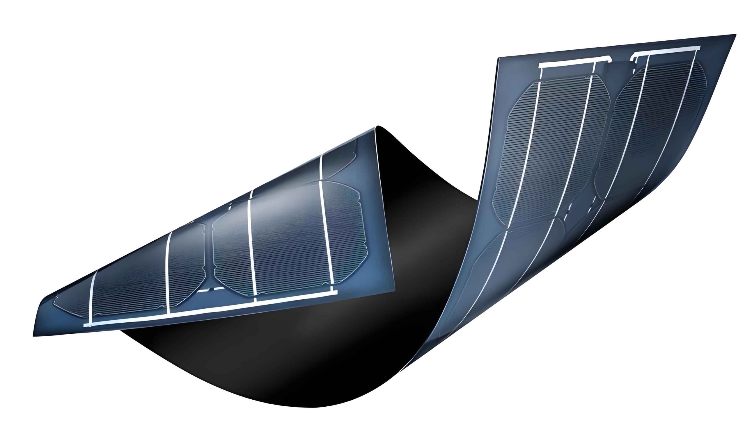
This article presents a comprehensive numerical investigation into the optical enhancement achieved by embedding periodic arrays of spherical metal nanoparticles directly into the crystalline silicon (c-Si) absorber layer of a model thin film solar panel. Using rigorous finite-difference time-domain (FDTD) simulations, we systematically explore the influence of key design parameters—including nanoparticle material, inter-particle spacing, and comparative shape—on the spectral absorption and the spatial distribution of photogenerated carriers. Our findings provide detailed insights and quantitative guidelines for optimizing plasmonic thin film solar panel designs to maximize performance.
Theoretical Foundation of Plasmonic Enhancement
The optical response of a small, sub-wavelength metal nanoparticle in a dielectric medium can be described by its polarizability, \(\alpha\). For a spherical nanoparticle of radius \(r\) with a complex dielectric function \(\epsilon_m(\omega)\) embedded in a medium with dielectric constant \(\epsilon_d\), the electrostatic polarizability in the quasi-static approximation (where \(r << \lambda\)) is given by:
$$
\alpha = 4\pi r^3 \frac{\epsilon_m(\omega) – \epsilon_d}{\epsilon_m(\omega) + 2\epsilon_d}
$$
The LSPR condition, leading to a maximum in polarizability and thus scattering/absorption cross-section, occurs when the denominator approaches zero: \(Re[\epsilon_m(\omega)] \approx -2\epsilon_d\). This condition is highly dependent on the material’s intrinsic dielectric function and the surrounding environment. The enhanced local electric field \(\mathbf{E}_{loc}\) at the nanoparticle surface is related to the incident field \(\mathbf{E}_0\) by:
$$
\mathbf{E}_{loc} = f \mathbf{E}_0, \quad \text{where } f \propto \left|\frac{\epsilon_m(\omega) – \epsilon_d}{\epsilon_m(\omega) + 2\epsilon_d}\right|
$$
This field enhancement is the primary mechanism for increased light-matter interaction in the neighboring semiconductor of a thin film solar panel. The subsequent absorption rate of photons in the semiconductor, \(G(\mathbf{r})\), at a position \(\mathbf{r}\) and for a wavelength \(\lambda\) is proportional to the square of the electric field magnitude and the material’s absorption coefficient:
$$
G(\mathbf{r}, \lambda) = \frac{2\pi c \epsilon_0 n(\lambda) k(\lambda)}{\lambda \hbar} |E(\mathbf{r}, \lambda)|^2
$$
where \(n(\lambda)\) and \(k(\lambda)\) are the real and imaginary parts of the semiconductor’s complex refractive index, \(\epsilon_0\) is the vacuum permittivity, \(c\) is the speed of light, and \(\hbar\) is the reduced Planck’s constant. Integrating this generation rate over the solar spectrum and the device volume yields the total photocurrent potential of the thin film solar panel.
Simulation Methodology and Device Structure
To accurately model the complex light-matter interactions in our proposed thin film solar panel, we employed the Finite-Difference Time-Domain (FDTD) method. This technique solves Maxwell’s equations directly in the time domain, making it exceptionally suitable for simulating electromagnetic wave interactions with intricate nanostructures. The fundamental equations solved are:
$$
\nabla \times \mathbf{H} = \frac{\partial \mathbf{D}}{\partial t}, \quad \nabla \times \mathbf{E} = -\frac{\partial \mathbf{B}}{\partial t}
$$
with the constitutive relations \(\mathbf{D} = \epsilon \mathbf{E}\) and \(\mathbf{B} = \mu \mathbf{H}\).
The simulated unit cell of the thin film solar panel is illustrated schematically and consists of the following layers, from top to bottom:
- SiNx Anti-Reflection Coating (ARC): A 40 nm thick layer to minimize front-surface reflection over the solar spectrum.
- Crystalline Silicon (c-Si) Absorber: The core active layer with a thickness of 1 μm, into which metal nanoparticles are embedded.
- Ag Back Reflector: A 200 nm thick silver layer to reflect any unabsorbed light back into the silicon layer for a second pass, further enhancing the optical path length.
The key innovation is the periodic array of two spherical metal nanoparticles embedded within the c-Si layer. They are positioned 200 nm below the Si/SiNx interface, situated within the charge carrier depletion region for optimal carrier collection. The radius \(r\) of each nanoparticle is 50 nm. The center-to-center spacing between the two nanoparticles in the unit cell is denoted as \(T\). A single unit cell with dimensions 0.4 μm × 0.4 μm in the periodic (x-y) plane was simulated. Periodic boundary conditions were applied laterally, and perfectly matched layers (PML) were used at the top and bottom boundaries to absorb outgoing waves. The source was a plane wave with the standard AM1.5 solar spectrum, incident normally from the top across the wavelength range of 300 nm to 1100 nm. The optical constants for all materials (Si, SiNx, Ag, Au, Cu, Al) were taken from experimental data (Palik).
| Parameter | Symbol | Value |
|---|---|---|
| Si Absorber Thickness | dSi | 1.0 μm |
| SiN ARC Thickness | dARC | 0.04 μm |
| Ag Back Reflector Thickness | dAg | 0.2 μm |
| Nanoparticle Depth | dNP | 0.2 μm |
| Nanoparticle Radius | r | 0.05 μm |
| Unit Cell Size (x, y) | – | 0.4 μm × 0.4 μm |
| Wavelength Range | λ | 0.3 – 1.1 μm |
Results and Discussion: Optimizing the Thin Film Solar Panel
1. The Impact of Nanoparticle Shape
We first investigated the fundamental benefit of embedding nanoparticles and the role of their shape. The baseline case is a thin film solar panel with no embedded nanoparticles. We compared it to panels with embedded Ag nanoparticles of two shapes: a sphere (radius 50 nm) and a cube (edge length 100 nm, providing a similar volume). The spacing \(T\) was fixed at 200 nm.
The spectral absorption \(A(\lambda)\) of the silicon layer alone was calculated by monitoring the net power flow into the layer. The results, shown graphically, reveal a striking difference. The baseline thin film solar panel shows characteristic absorption: high in the short wavelength (blue/green) region where silicon’s absorption coefficient is high, followed by a steep decline for wavelengths beyond 800 nm due to the weak absorption of near-infrared (NIR) light in the thin layer.
Embedding Ag nanoparticles drastically alters the spectrum. Most notably, both nanoparticle shapes induce a significant enhancement in absorption across the 800-1100 nm NIR range, precisely where the thin film solar panel is most deficient. This broadband enhancement is a direct consequence of the LSPR-mediated light trapping and local field enhancement. Quantitative integration of the absorption curves over the entire spectrum shows that the spherical nanoparticles provide a 23.1% increase in total absorbed photons compared to the baseline, outperforming the cubic shape which produced a slightly narrower enhancement peak.
The superiority of the sphere can be attributed to its lack of sharp corners, which minimizes damping losses and leads to a stronger and broader plasmonic resonance beneficial for thin film solar panel applications. The spatial distribution of the photogeneration rate \(G(x,z)\) confirms this. While both nanoparticles create localized “hot spots” of high carrier generation around them, the sphere induces a more extensive and uniform region of enhanced generation above and below it, leading to better overall performance of the thin film solar panel.
| Structure | Integrated Absorption (300-1100 nm) [a.u.] | Enhancement vs. Baseline | Key Spectral Feature |
|---|---|---|---|
| Baseline (No NPs) | 1.00 | – | Rapid drop beyond 800 nm |
| With Ag Cubes | 1.19 | +19% | Strong but narrow NIR peak |
| With Ag Spheres | 1.23 | +23.1% | Broad, strong NIR enhancement |
2. The Role of Nanoparticle Material
The choice of metal is critical, as it determines the spectral position and strength of the LSPR via its dielectric function \(\epsilon_m(\omega)\). We simulated thin film solar panels with embedded spheres of four different metals: Silver (Ag), Gold (Au), Copper (Cu), and Aluminum (Al), keeping \(r = 50\) nm and \(T = 200\) nm.
The complex refractive indices (\(n + ik\)) of these metals govern their behavior. Ag, Au, and Cu have relatively similar optical properties in the visible-NIR, with negative real permittivity supporting surface plasmons. Al, however, has a significantly different dielectric function, supporting plasmon resonances at higher energies (UV/blue) but also exhibiting interesting behavior in the NIR.
The absorption spectra reveal distinct material-dependent responses. As expected, the Ag, Au, and Cu nanoparticles produce very similar absorption curves, with strong, overlapping enhancement peaks in the 800-1100 nm range. This correlates well with their similar LSPR conditions in a silicon environment.
The Al nanoparticle result is particularly interesting for thin film solar panel design. While it shows less pronounced sharp peaks compared to Ag in the NIR, it produces a broader and more sustained elevation of absorption across the 700-1000 nm range. This broadband enhancement is highly desirable for maximizing the photocurrent under the solar spectrum. Analysis of the photogeneration map for the Al case shows not only strong localization near the nanoparticles but also the emergence of an ordered pattern of enhanced generation regions in the silicon above the nanoparticles, indicating efficient coupling and redistribution of light within the thin film solar panel absorber.
| Material | LSPR Peak Approx. (in Si) [nm] | Primary Enhancement Band | Advantage for Thin Film Solar Panels |
|---|---|---|---|
| Silver (Ag) | ~900-1000 | 800-1100 nm (Strong, sharp peak) | Highest peak enhancement in NIR |
| Gold (Au) | ~900-1050 | 800-1100 nm (Strong peak) | Good stability, but more lossy than Ag |
| Copper (Cu) | ~850-950 | 800-1100 nm (Strong peak) | Lower cost, but prone to oxidation |
| Aluminum (Al) | UV/Visible & Broad NIR | 700-1000 nm (Broad, sustained lift) | Broadband response, low cost, CMOS-compatible |
3. Tuning Inter-Particle Spacing (Coupling Effects)
The interaction between neighboring nanoparticles—plasmonic coupling—can significantly modify the resonance properties. To study this in our thin film solar panel context, we fixed the material to Al (due to its promising broadband response) and varied the center-to-center spacing \(T\) between the two nanoparticles in the unit cell to 100 nm, 150 nm, and 200 nm.
The absorption spectra demonstrate a clear spacing dependence. For \(T = 100\) nm (nanoparticles nearly touching), the absorption is superior in the shorter wavelength range (450-750 nm). However, at the critical longer wavelengths of 900 nm and 1000 nm, the intermediate spacing of \(T = 150\) nm produces the widest and highest absorption peaks, outperforming both the closer (\(T=100\) nm) and farther (\(T=200\) nm) configurations.
This non-monotonic behavior is a signature of plasmonic coupling. At very small separations, strong near-field coupling can shift and dampen resonances. An optimal separation exists where the coupled mode provides maximal field enhancement and radiative scattering into the silicon layer of the thin film solar panel. The photogeneration maps visually corroborate this: the \(T = 150\) nm configuration exhibits the most extensive and uniformly enhanced carrier generation in the upper region of the silicon absorber, minimizing low-generation “dead zones” and thus promising higher overall current collection.
The coupling between two spherical nanoparticles can be modeled by considering the modified polarizability in the presence of the other particle’s dipole field. The effective field exciting nanoparticle 1 is \(\mathbf{E}_1 = \mathbf{E}_0 + \mathbf{E}_{21}\), where \(\mathbf{E}_{21}\) is the field from nanoparticle 2 at the location of nanoparticle 1. For dipoles aligned with the incident field and separated by distance \(T\) along the x-axis, this leads to a modified resonance condition influenced by terms like \(1/T^3\). This explains the sensitive dependence of the thin film solar panel’s spectral response on the parameter \(T\).
| Spacing (T) | Absorption at 450-750 nm | Absorption Peak at ~900-1000 nm | Uniformity of G(x,z) in Upper Si |
|---|---|---|---|
| 0.10 μm | Best | Good, but narrower peak | Low (large low-G zone above NPs) |
| 0.15 μm | Good | Best (widest & highest peak) | Best (most uniform enhancement) |
| 0.20 μm | Good | Good | Good |
Conclusion and Perspectives for Thin Film Solar Panel Development
This numerical study systematically demonstrates the profound potential of embedded metal nanoparticles to overcome the intrinsic light absorption limitations of thin film solar panels. By exciting localized surface plasmon resonances, these nanostructures act as efficient optical antennas, concentrating light and enhancing the effective absorption path length within an ultra-thin crystalline silicon absorber.
Our key findings for optimizing such a plasmonic thin film solar panel are:
- Shape Matters: Spherical nanoparticles are superior to cubic ones, providing broader spectral enhancement and a more uniform boost in photogeneration, leading to a 23.1% integrated absorption increase for Ag spheres.
- Material Choice is Strategic: While Ag provides the strongest sharp resonance in the NIR, Aluminum emerges as a highly compelling candidate due to its ability to induce a broadband enhancement from 700-1000 nm, its low cost, and compatibility with standard semiconductor processing, making it ideal for manufacturable thin film solar panels.
- Coupling Can Be Optimized: The spacing between nanoparticles is not trivial. An optimal separation (e.g., \(T = 150\) nm for Al spheres) exists where plasmonic coupling yields the widest and highest absorption peaks in the crucial near-infrared region and the most favorable distribution of photogenerated carriers.
The insights gained from this work, particularly the quantified relationships between nanoparticle parameters and absorption enhancement, provide a valuable roadmap for the design of high-efficiency, next-generation thin film solar panels. Future work should focus on extending the analysis to multi-layer nanoparticle arrays, different periodic arrangements (e.g., hexagonal lattices), and the integration of these plasmonic structures with other light-trapping schemes (e.g., textured interfaces). Furthermore, a coupled opto-electrical simulation would be essential to fully translate the enhanced optical absorption into predicted electrical efficiency gains, accounting for potential parasitic absorption and carrier recombination effects at the metal-semiconductor interfaces. The pursuit of these advanced designs holds the key to making thin film solar panel technology a more dominant and efficient player in the global renewable energy landscape.
| Design Parameter | Recommended Choice | Primary Reason |
|---|---|---|
| Nanoparticle Shape | Sphere | Broader resonance, lower losses, more uniform field enhancement. |
| Nanoparticle Material | Aluminum (Al) or Silver (Ag) | Al for broadband, low-cost enhancement; Ag for maximum peak NIR enhancement. |
| Nanoparticle Radius (r) | ~50 nm (used in study) | Strong dipole resonance within solar spectrum; amenable to fabrication. |
| Inter-Particle Spacing (T) | ~1.5r to 3r (e.g., 150 nm for r=50 nm) | Optimizes plasmonic coupling for broad, high absorption peaks. |
| Embedding Depth in Si | Within depletion region (~200 nm from surface) | Ensures enhanced carriers are generated in high-field region for efficient collection. |