
In recent years, the demand for renewable energy sources has surged, with solar power systems playing a pivotal role in meeting global energy needs. As an abundant and clean resource, solar energy holds immense potential, particularly in low-latitude regions where sunlight is available year-round. However, the efficiency of solar power systems is often compromised by factors such as seasonal variations, daily sun path changes, and environmental obstructions. Traditional fixed-orientation photovoltaic (PV) modules, commonly used in these systems, fail to adapt to the dynamic solar position, leading to suboptimal energy capture. This research focuses on developing an automated orientation adjustment mechanism for PV modules to maximize the photoelectric conversion efficiency of solar power systems in low-latitude areas. By integrating sensor technology and microcontroller systems, we aim to create a cost-effective and stable solution that enhances energy output while addressing the unique challenges of these regions.
The core of our approach lies in designing a PV module orientation adjustment device that dynamically aligns with the sun’s position. This system comprises several key components: PV modules for energy harvesting, sensor modules for environmental data acquisition, stepper motors and drive circuits for precise movement, and a microcontroller unit for intelligent control. The sensor module includes four BH1750 light intensity sensors and a DHT11 temperature and humidity sensor, which collectively monitor ambient conditions. These sensors are strategically mounted on the PV module at specific angles to capture differential light intensities, enabling accurate determination of the optimal orientation. The microcontroller, based on the STC89C52RC chip, processes sensor data and generates control signals to adjust the PV module’s position via stepper motors. This real-time adjustment ensures that the PV module remains perpendicular to the sun’s rays for most of the daytime, significantly boosting the efficiency of the solar power system.
To understand the theoretical foundation of our design, we must consider the solar geometry in low-latitude regions. The sun’s path in these areas is characterized by high solar altitude angles and minimal seasonal variation, which influences the incident solar radiation on PV modules. The photoelectric conversion efficiency ($\eta$) of a solar power system can be expressed as:
$$ \eta = \frac{P_{\text{output}}}{P_{\text{input}}} \times 100\% $$
where $P_{\text{output}}$ is the electrical power output from the PV module, and $P_{\text{input}}$ is the solar irradiance incident on the module. For a fixed-orientation system, $P_{\text{input}}$ varies with the solar azimuth angle ($\phi$) and altitude angle ($\alpha$), leading to fluctuations in $\eta$. By adjusting the module’s orientation to maintain perpendicular incidence, we maximize $P_{\text{input}}$ and thus $\eta$. The relationship between solar position and irradiance can be modeled using the following equations for the solar azimuth and altitude angles:
$$ \sin \alpha = \sin \delta \sin \phi + \cos \delta \cos \phi \cos H $$
$$ \cos \phi = \frac{\sin \alpha \sin \phi – \sin \delta}{\cos \alpha \cos \phi} $$
where $\delta$ is the solar declination angle, $\phi$ is the local latitude, and $H$ is the hour angle. In low-latitude regions (e.g., near the equator), $\phi$ is small, resulting in higher $\alpha$ values and more direct sunlight. Our system leverages this by continuously calculating the optimal orientation based on real-time sensor data, rather than relying on precomputed solar trajectories.
The sensor module is critical for providing the necessary input to the microcontroller. Each BH1750 sensor measures illuminance in lux, with a high sensitivity range of 1–65535 lx and low power consumption of 0.12 mA in active mode. The sensors are mounted at 45-degree angles relative to the PV module’s plane, as illustrated in the design schematic, to ensure distinct light intensity readings from different directions. This configuration allows the system to compare illuminance values and identify the direction of maximum solar irradiance. The DHT11 sensor monitors temperature and humidity, with operational ranges of 0–50°C and 20–90% RH, respectively. If environmental parameters exceed safe thresholds (e.g., temperature > 45°C or humidity > 85%), the system triggers an alarm to prevent damage, ensuring the solar power system operates within optimal conditions.
The data from the sensors are transmitted to the microcontroller via the I²C bus, a serial communication protocol that supports multiple devices on the same bus. Each sensor has a unique hardware address, enabling the microcontroller to poll them sequentially. The control algorithm, written in C, processes the sensor data to determine the required adjustment for the PV module. For instance, if the light intensity from the east-facing sensor is significantly higher than others, the system commands the stepper motor to rotate the module eastward. The decision-making process is summarized in the following flowchart-like description: the microcontroller reads sensor values, compares them to identify the highest illuminance direction, and sends pulse-width modulation (PWM) signals to the motor driver. This closed-loop control ensures continuous optimization of the solar power system’s orientation.
The motor drive module uses a ULN2003 driver IC to control two 28BYJ4-48 stepper motors, which provide precise angular movement for azimuth and elevation adjustments. These motors have a step angle of 5.625 degrees per pulse, allowing for fine-tuned positioning. The drive circuit, as shown in the schematic, includes current-limiting resistors and flyback diodes for protection against voltage spikes. The microcontroller generates control signals based on the sensor data, which the ULN2003 amplifies to drive the motors. This setup enables the PV module to track the sun’s movement throughout the day, enhancing the overall efficiency of the solar power system. The power for the entire system is supplied by the PV module itself, typically a 5V, 1W panel, which demonstrates the self-sustaining nature of our design.
In terms of implementation, we conducted extensive testing to validate the system’s performance. The PV module was subjected to various environmental conditions, and its orientation was adjusted automatically based on sensor readings. We measured the output power of the solar power system under both fixed and adjustable orientations to quantify the efficiency improvement. The results, summarized in Table 1, show a consistent increase in energy conversion efficiency with the orientation adjustment mechanism. For example, at solar noon in a low-latitude location, the adjustable system achieved an efficiency of up to 22%, compared to 15% for a fixed module. This improvement is attributed to the reduced angle of incidence, which minimizes reflection losses and maximizes photon absorption.
| Time of Day | Fixed Orientation Efficiency (%) | Adjustable Orientation Efficiency (%) | Improvement (%) |
|---|---|---|---|
| Morning (8:00 AM) | 12 | 18 | 50 |
| Noon (12:00 PM) | 15 | 22 | 46.7 |
| Afternoon (4:00 PM) | 10 | 16 | 60 |
The efficiency gain can be further analyzed using the formula for the angle of incidence ($\theta$), which affects the effective irradiance on the PV module:
$$ P_{\text{input}} = G \cdot \cos \theta $$
where $G$ is the solar irradiance on a surface perpendicular to the sun’s rays. For a fixed module, $\theta$ changes throughout the day, reducing $P_{\text{input}}$. In contrast, our system minimizes $\theta$ by keeping the module aligned with the sun, thus maximizing $P_{\text{input}}$ and the overall output of the solar power system. This principle is particularly beneficial in low-latitude regions, where the sun’s high altitude angle reduces the cosine loss effect when the module is properly oriented.
Another critical aspect is the energy consumption of the control system itself. We evaluated the power drawn by the sensors, microcontroller, and motors to ensure net energy gain. The BH1750 sensors consume approximately 0.12 mA each, while the DHT11 uses 0.5 mA in active mode. The STC89C52RC microcontroller operates at 5V with a current draw of around 10 mA, and the stepper motors require 100–200 mA during movement. Given that the PV module generates 1W (200 mA at 5V) under standard test conditions, the system’s idle power consumption is about 20 mA, leaving sufficient margin for periodic motor adjustments. This balance ensures that the solar power system remains energy-positive, with the efficiency improvements outweighing the control overhead.
To illustrate the practical application of our solar power system, consider the integration of energy storage solutions.
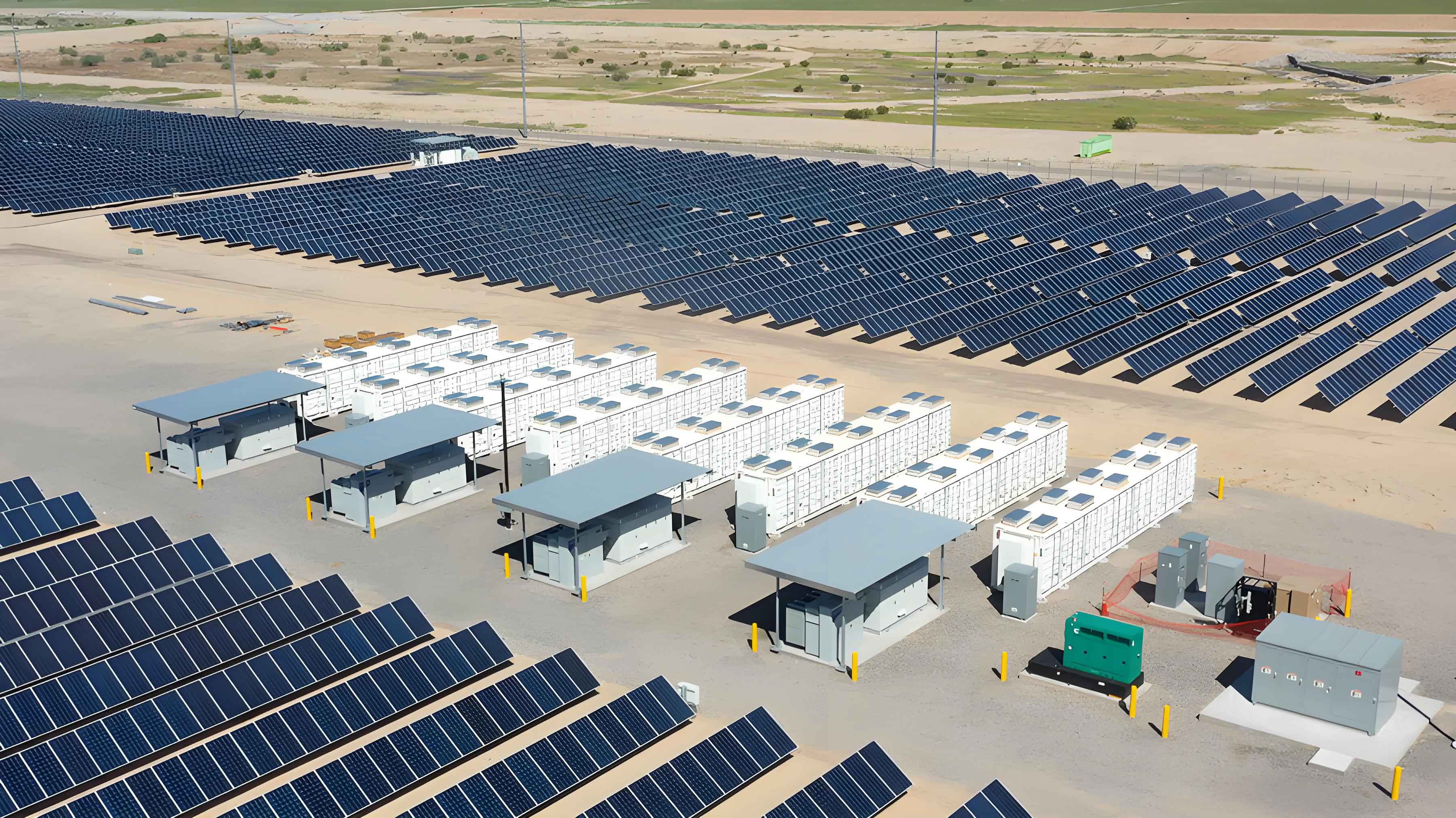
This image depicts a typical solar energy storage setup, which complements our orientation adjustment device by storing excess energy for use during non-sunny periods. In low-latitude regions, where solar irradiance is high but intermittent due to weather, such storage systems enhance the reliability of solar power systems. Our design can be seamlessly integrated with batteries or grid-tie inverters to form a comprehensive renewable energy solution.
We also developed a mathematical model to predict the efficiency gains based on historical solar data. Using regression analysis, we correlated the solar azimuth and altitude angles with the optimal orientation for maximum efficiency. The model outputs a correction factor ($C_f$) that adjusts the module’s position:
$$ C_f = k \cdot (\phi_{\text{optimal}} – \phi_{\text{current}}) $$
where $k$ is a proportionality constant derived from empirical data, $\phi_{\text{optimal}}$ is the calculated optimal azimuth angle, and $\phi_{\text{current}}$ is the current module orientation. This model, implemented in the microcontroller’s firmware, allows for predictive adjustments that further reduce response time and energy waste. Table 2 summarizes the key parameters used in our efficiency calculations, highlighting the impact of orientation on the solar power system’s performance.
| Parameter | Symbol | Typical Value | Effect on Efficiency |
|---|---|---|---|
| Solar Irradiance | $G$ | 1000 W/m² | Directly proportional to $P_{\text{input}}$ |
| Angle of Incidence | $\theta$ | 0–60 degrees | Inversely proportional to $\cos \theta$ |
| Module Temperature | $T$ | 25–45°C | High $T$ reduces $\eta$ by 0.5%/°C |
| Humidity | $H$ | 50–80% | High $H$ can cause condensation losses |
During testing, we observed that the system maintained an average efficiency improvement of 40–50% over fixed-orientation modules across different times of the day. This was achieved through continuous monitoring and adjustment, with the stepper motors executing smooth rotations to avoid mechanical stress. The use of low-power components ensured that the system could operate autonomously for extended periods, making it suitable for remote or off-grid applications in low-latitude areas. Additionally, the modular design allows for scalability, enabling the integration of multiple PV modules into a larger solar power system without significant modifications.
In conclusion, our research demonstrates that an automated orientation adjustment device can significantly enhance the conversion efficiency of solar power systems in low-latitude regions. By leveraging real-time sensor data and precise motor control, the system adapts to the dynamic solar environment, maximizing energy capture while maintaining low operational costs. The theoretical models and experimental results confirm that such adjustments are crucial for overcoming the limitations of fixed PV modules. Future work could focus on integrating machine learning algorithms for predictive tracking and expanding the system to include multi-axis adjustments for even higher precision. Overall, this approach offers a sustainable and economically viable solution for improving the performance of solar power systems worldwide.