
The proliferation of distributed generation systems has positioned the utility interactive inverter as a critical interface for integrating renewable energy sources like photovoltaics into the main grid. Its reliable and stable operation is paramount for the overall health of the power system. To ensure synchronization of the injected current with the grid voltage, a phase-locked loop (PLL) is ubiquitously employed to generate the current reference. Furthermore, the electrical grid at the point of common coupling (PCC) often exhibits “weak grid” characteristics, characterized by non-negligible grid impedance and significant background voltage harmonics, due to long-distance transmission and the connection of numerous nonlinear loads. To mitigate the adverse impact of grid voltage distortion on the quality of the injected current, a proportional grid voltage feedforward strategy is commonly adopted. While effective under stiff grid conditions, this combination introduces significant stability challenges when the grid impedance varies over a wide range. The presence of grid impedance creates a strong coupling with the inverter’s internal current control loop, reducing system stability margins. Concurrently, an increased grid impedance lowers the bandwidth of the current loop, causing it to interact with the PLL bandwidth in the low-frequency region, further degrading the inverter’s stability. This paper addresses this critical issue by first establishing a comprehensive output impedance model that accounts for the influence of both grid voltage proportional feedforward and the PLL. Based on the impedance-based stability criterion, the destabilizing effects are analyzed. Subsequently, a composite impedance remodeling strategy based on enhanced grid voltage feedforward is proposed. This strategy reshapes the inverter’s output impedance to significantly improve stability under wide-range grid impedance variations, ensuring high-quality grid current injection.
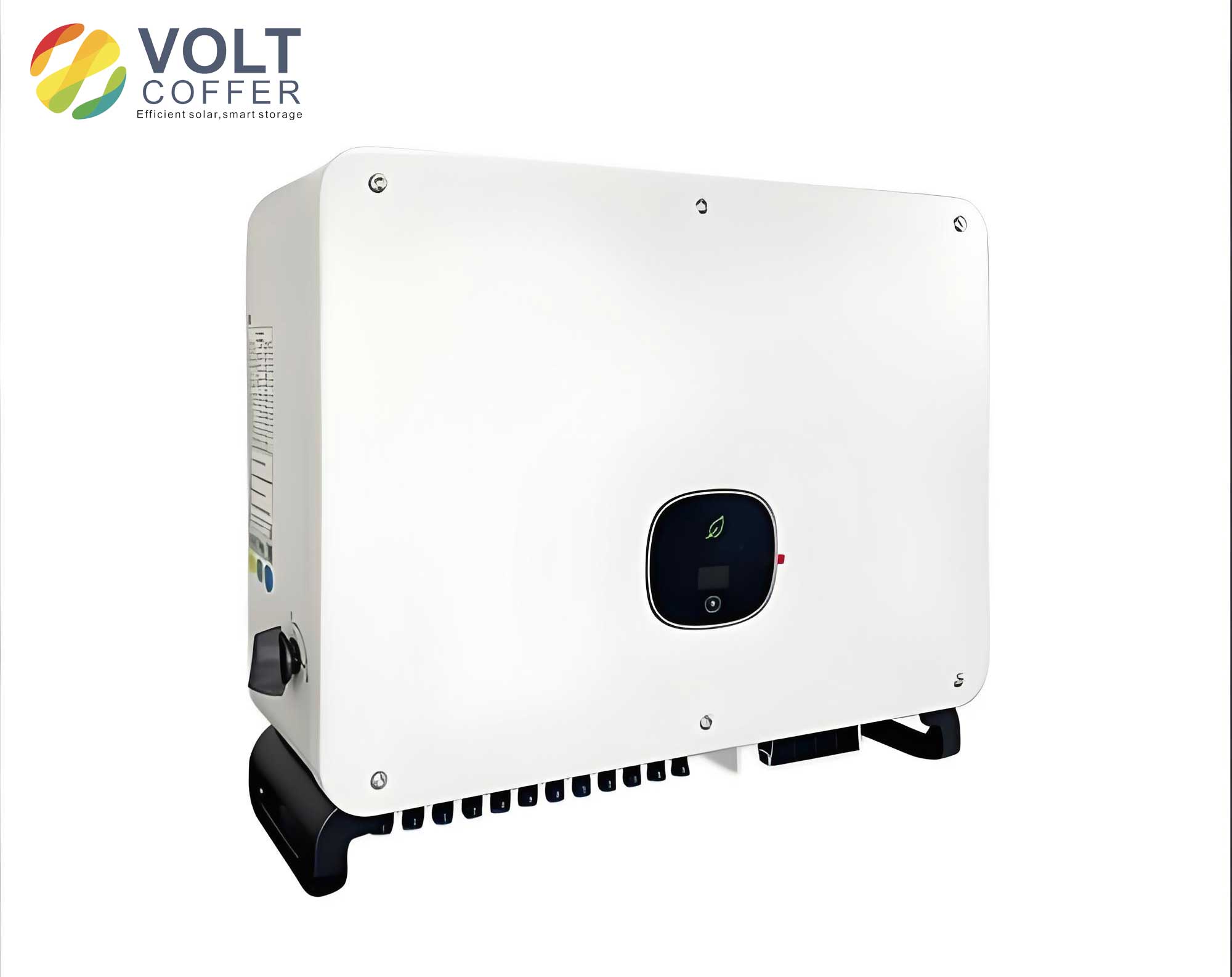
System Modeling and Stability Analysis Under Weak Grid Conditions
Output Impedance Modeling of the LCL-Type Utility Interactive Inverter
The topology and control block diagram of an LCL-type utility interactive inverter employing conventional proportional grid voltage feedforward is considered. The system parameters are defined as follows: $L_1$ is the inverter-side inductor, $C_f$ is the filter capacitor, $L_2$ is the grid-side inductor, $L_g$ is the grid impedance (assumed to be purely inductive, $Z_g(s) = sL_g$, representing the worst-case scenario), $U_{dc}$ is the DC-link voltage, $U_{pcc}$ is the PCC voltage, $i_c$ is the capacitor current, $i_g$ is the grid current, $I^*$ is the current amplitude reference, $i_{ref}$ is the current reference signal, $K_{pwm}$ is the equivalent inverter bridge gain, $K_d$ is the active damping feedback coefficient, and $H_{i1}$ is the grid current sampling coefficient.
The controller includes a quasi-proportional resonant (QPR) current regulator $G_c(s)$, a proportional grid voltage feedforward block $G_f(s)$, and a PLL block $G_{PLL}(s)$. Their transfer functions are given by:
$$
G_c(s) = K_p + \frac{2K_r\omega_c s}{s^2 + 2\omega_c s + \omega_0^2}
$$
where $K_p$ and $K_r$ are the proportional and resonant coefficients, $\omega_0$ is the fundamental angular frequency (314 rad/s), and $\omega_c$ is the controller bandwidth (3.14 rad/s).
$$
G_f(s) = \frac{1}{K_{pwm}}
$$
$$
G_{PLL}(s) = \frac{0.5[K_{pp}(s – j\omega_0) + K_{pi}]}{(s – j\omega_0)^2 + U_m[K_{pp}(s – j\omega_0) + K_{pi}]}
$$
where $K_{pp}$ and $K_{pi}$ are the PI controller parameters of the PLL, and $U_m$ is the amplitude of $U_{pcc}$.
By manipulating the control block diagram, the grid current $i_g(s)$ can be derived. The utility interactive inverter can then be represented by its equivalent output impedance $Z_{out}(s)$ in parallel with the grid impedance $Z_g(s)$, driven by the grid voltage $U_{pcc}(s)$. The composite output impedance $Z_{out}(s)$ is found to consist of three parallel components stemming from the current control loop $Z_{inv}(s)$, the grid voltage feedforward loop $Z_{GVF}(s)$, and the PLL $Z_{PLL}(s)$:
$$
Z_{out}(s) = \left( \frac{1}{Z_{inv}(s)} + \frac{1}{Z_{GVF}(s)} + \frac{1}{Z_{PLL}(s)} \right)^{-1}
$$
where the individual components are:
$$
\begin{aligned}
Z_{inv}(s) &= \frac{1 + G_c(s)G_{X1}(s)G_{X2}(s)H_{i1}}{G_{X2}(s)} \\
Z_{GVF}(s) &= -\frac{1 + G_c(s)G_{X1}(s)G_{X2}(s)H_{i1}}{G_f(s)G_{X1}(s)G_{X2}(s)} \\
Z_{PLL}(s) &= -\frac{1 + G_c(s)G_{X1}(s)G_{X2}(s)H_{i1}}{I^*G_{PLL}(s)H_{i1}G_c(s)G_{X1}(s)G_{X2}(s)}
\end{aligned}
$$
with $G_{X1}(s)$ and $G_{X2}(s)$ being transfer functions related to the LCL filter and active damping:
$$
G_{X1}(s) = \frac{K_{pwm}}{s^2 C_f L_1 + s K_d K_{pwm} C_f + 1}, \quad G_{X2}(s) = \frac{s^2 L_1 C_f + s K_d K_{pwm} C_f + 1}{s^3 L_1 L_2 C_f + s^2 K_d K_{pwm} C_f L_2 + s(L_1 + L_2)}
$$
The final expression for the output impedance of the utility interactive inverter, considering both feedforward and PLL effects, is:
$$
Z_{out}(s) = \frac{1 + G_c(s)G_{X1}(s)G_{X2}(s)H_{i1}}{G_{X2}(s) – G_f(s)G_{X1}(s)G_{X2}(s) – I^*G_{PLL}(s)H_{i1}G_c(s)G_{X1}(s)G_{X2}(s)}
$$
Stability Analysis Based on the Impedance Criterion
The stability of the utility interactive inverter system is assessed using the impedance-based Nyquist criterion. For stability, two conditions must be met: 1) The system must be stable when connected to a stiff grid ($Z_g(s)=0$). 2) When connected to a weak grid ($Z_g(s) \neq 0$), the ratio $Z_{out}(s)/Z_g(s)$ must satisfy the Nyquist criterion. A critical practical condition derived from this is that at the frequency $\omega_s$ where the magnitudes of $|Z_{out}(j\omega)|$ and $|Z_g(j\omega)|$ intersect, the phase margin $PM$ must be positive:
$$
PM = 180^\circ – ( \angle Z_g(j\omega_s) – \angle Z_{out}(j\omega_s) ) > 0^\circ
$$
Given a purely inductive grid impedance $\angle Z_g(j\omega_s) = 90^\circ$, the stability condition simplifies to requiring the phase of the inverter output impedance at the intersection frequency to satisfy:
$$
\angle Z_{out}(j\omega_s) > -90^\circ
$$
An analysis of the Bode plot for $Z_{out}(s)$ reveals the destabilizing effects. While the proportional grid voltage feedforward can increase the magnitude of the output impedance at certain frequencies (potentially improving harmonic rejection), it introduces a significant phase lag of approximately $90^\circ$ in the mid-frequency range. When the influence of the PLL is further incorporated, the phase of $Z_{out}(s)$ in the low-frequency region is drastically reduced. As the grid impedance $L_g$ increases, the intersection frequency $\omega_s$ moves lower, where this severe phase lag exists, critically reducing the phase margin and potentially leading to instability. This underscores the necessity for a coordinated strategy to reshape the output impedance of the utility interactive inverter.
Composite Impedance Remodeling Strategy Based on Grid Voltage Feedforward
To counteract the destabilizing effects identified, a two-pronged composite impedance remodeling strategy is proposed, targeting both the grid voltage feedforward path and the influence of the PLL.
Impedance Reshaping via a Low-Pass Filter in the Feedforward Path
First, we address the phase lag introduced by the proportional feedforward. Ignoring the PLL’s effect momentarily, the output impedance is:
$$
Z’_{out}(s) = \frac{1 + G_c(s)G_{X1}(s)G_{X2}(s)H_{i1}}{G_{X2}(s) – G_f(s)G_{X1}(s)G_{X2}(s)}
$$
The denominator term $M(s) = G_{X2}(s) – G_f(s)G_{X1}(s)G_{X2}(s)$ is responsible for the undesirable phase characteristic. To reshape it, a first-order low-pass filter $L(s)$ is introduced in series with the proportional feedforward block:
$$
L(s) = K \frac{\omega_L}{s + \omega_L}
$$
where $K$ is a proportional coefficient and $\omega_L$ is the cutoff angular frequency. The modified feedforward becomes $L(s)G_f(s)$, and the resulting output impedance $Z_{out-1}(s)$ is:
$$
Z_{out-1}(s) = \frac{1 + G_c(s)G_{X1}(s)G_{X2}(s)H_{i1}}{G_{X2}(s) – L(s)G_f(s)G_{X1}(s)G_{X2}(s)}
$$
The parameters $K$ and $\omega_L$ are tuned to achieve a trade-off. A lower $\omega_L$ improves the phase margin more significantly but attenuates the harmonic suppression capability at higher frequencies. To maintain rejection of common low-order grid harmonics (e.g., up to the 13th), $\omega_L$ is set to 650 Hz (approximately 4082 rad/s). Adjusting $K$ allows for fine-tuning the phase boost in the low-frequency region; a value of $K=0.5$ is selected to provide substantial phase lead while minimizing impact on the magnitude at frequencies above the fundamental. This modification effectively elevates the phase of the utility interactive inverter’s output impedance above $-90^\circ$ for a wide mid-to-high frequency range.
Mitigating PLL Influence through an Additional Feedforward Branch
The impedance reshaping via the low-pass filter alone is insufficient to counteract the strong negative damping effect introduced by the PLL in the low-frequency range. From the initial model, the PLL contributes an impedance component $Z_{PLL}(s)$ in parallel with $Z_{out}(s)$. The proposed solution is to inject a compensating signal that effectively parallels a virtual impedance $Z_X(s) = -Z_{PLL}(s)$, thereby canceling out the PLL’s effect. Control block diagram manipulation shows this can be implemented by adding an auxiliary feedforward branch with a transfer function $N(s)$ derived from $-1/Z_X(s)$:
$$
N(s) = I^* H_{i1} G_c(s) G_{PLL}(s)
$$
To ensure practical realizability, a second-order approximation $N'(s)$ is used:
$$
N'(s) = I^* H_{i1} K_p \frac{0.5(K_{pp}s + K_{pi})}{s^2 + U_m(K_{pp}s + K_{pi})}
$$
This auxiliary feedforward path is integrated into the control structure. The final, composite output impedance $Z_{out-3}(s)$ of the utility interactive inverter after applying both remodeling techniques is:
$$
Z_{out-3}(s) = \frac{1 + G_c(s)G_{X1}(s)G_{X2}(s)H_{i1}}{G_{X2}(s) – G_{X2}(s)[L(s)G_f(s) – N'(s)]G_{X1}(s) – I^*G_{PLL}(s)G_c(s)G_{X1}(s)G_{X2}(s)H_{i1}}
$$
This formulation represents the core of the proposed composite strategy, simultaneously mitigating the phase lag from the main feedforward and the negative-resistance effect from the PLL.
Robustness Analysis and Performance Evaluation
The robustness of the proposed composite impedance remodeling strategy is evaluated by examining the phase margin of the system $PM = 90^\circ + \angle Z_{out-3}(j\omega_s)$ across a wide range of grid impedances, commonly expressed as the Short Circuit Ratio (SCR), where a lower SCR indicates a weaker grid. The system parameters used for analysis are summarized in the table below.
| Parameter | Symbol | Value |
|---|---|---|
| Rated Power | $P$ | 18 kW |
| DC-link Voltage | $U_{dc}$ | 400 V |
| Grid Voltage (RMS) | $U_g$ | 220 V |
| Fundamental Frequency | $f_0$ | 50 Hz |
| Inverter-side Inductor | $L_1$ | 0.6 mH |
| Filter Capacitor | $C_f$ | 10 µF |
| Grid-side Inductor | $L_2$ | 0.15 mH |
| Current Controller $K_p$ | $K_p$ | 0.5 |
| Current Controller $K_r$ | $K_r$ | 45 |
| Active Damping Gain | $K_d$ | 0.15 |
| Switching Frequency | $f_{sw}$ | 10 kHz |
Bode plots of $Z_{out}(s)$ (original) and $Z_{out-3}(s)$ (with composite remodeling) are compared. The proposed strategy dramatically improves the phase characteristics across all frequencies, particularly in the low-frequency region, while causing only minimal reduction in magnitude. The improvement in phase margin is quantified for different grid strengths:
| Grid Condition | Grid Impedance $L_g$ | SCR | Phase Margin (Original) | Phase Margin (Proposed) |
|---|---|---|---|---|
| Stiff/Moderate | 2.5 mH | 10 | 3° | 41.7° |
| Weak | 5.1 mH | 5 | -12° | 40.0° |
| Very Weak | 10.2 mH | 2.5 | -34° | 33.1° |
The results are compelling. The original control strategy leads to negative phase margins (instability) for SCR ≤ 5. In contrast, the proposed composite impedance remodeling strategy maintains phase margins above 33° even for an SCR as low as 2.5, which comfortably exceeds the typical engineering requirement of 30°. This demonstrates that the strategy significantly enhances the robustness and stability range of the utility interactive inverter in weak grids. Importantly, the phase at the fundamental frequency remains unchanged, ensuring proper unity power factor operation.
Simulation and Experimental Verification
The effectiveness of the proposed composite strategy was validated through detailed simulation and experimental tests on an 18 kW LCL-type utility interactive inverter prototype.
Simulation Results: The system was simulated under varying grid strengths. With the conventional strategy, as the SCR decreased (i.e., $L_g$ increased), the grid current waveform became severely distorted, with a Total Harmonic Distortion (THD) exceeding 45% for SCR=2.5, making it unsuitable for grid interconnection. After implementing the proposed composite impedance remodeling strategy, the current quality was restored to an excellent level. The current waveforms became sinusoidal and synchronized with the grid voltage. The THD was reduced to 1.46% under the very weak grid condition (SCR=2.5), demonstrating a remarkable improvement in stability and performance.
Experimental Results: The experimental platform based on an RtLab control system confirmed the simulation findings. Under weak grid conditions (SCR=5 and SCR=2.5), the experimental waveforms for the conventional control showed highly distorted grid currents. After applying the proposed impedance remodeling strategy, the current distortion was effectively suppressed, resulting in clean, sinusoidal current injection that complies with grid codes. Furthermore, the dynamic performance was tested by subjecting the utility interactive inverter to a step change in the current reference from 20 A to 30 A under the very weak grid condition (SCR=2.5). The grid current tracked the new reference within approximately one fundamental cycle, confirming that the proposed strategy does not compromise the system’s dynamic response while ensuring robust stability.
Conclusion
This paper has investigated the stability degradation of LCL-type utility interactive inverters in weak grids, exacerbated by the combined effects of proportional grid voltage feedforward and the phase-locked loop. A detailed output impedance model incorporating these effects was developed, and analysis based on the impedance stability criterion clearly identified the sources of phase margin reduction. To address this challenge, a novel composite impedance remodeling strategy based on enhanced grid voltage feedforward was proposed and thoroughly analyzed. The strategy employs two key modifications: 1) inserting a low-pass filter in the proportional feedforward path to reshape the mid-frequency phase characteristics, and 2) adding an auxiliary feedforward branch designed to cancel the negative damping effect introduced by the PLL in the low-frequency region. The composite action significantly reshapes the output impedance of the utility interactive inverter. Analytical, simulation, and experimental results consistently demonstrate that the proposed strategy dramatically improves the system’s phase margin across a wide range of grid impedances. It enables stable and high-quality operation of the utility interactive inverter even under very weak grid conditions (e.g., SCR down to 2.5), thereby greatly expanding the reliable operating envelope of distributed generation systems connected to non-ideal grids. The strategy is effective and practical, offering a viable solution for enhancing the robustness of modern utility interactive inverters.