
The on-grid inverter serves as the critical power electronic interface connecting distributed energy resources, such as photovoltaic arrays and energy storage systems, to the main utility grid. Its primary functions encompass power conversion, voltage regulation, and, most importantly, precise real and reactive power delivery. The PQ control strategy, which independently governs active power (P) and reactive power (Q), is fundamental for enabling on-grid inverters to provide grid support services and respond to system demands. However, the conventional implementation of PQ control often relies on linear Proportional-Integral (PI) regulators. While simple, PI controllers face significant challenges in parameter tuning for the nonlinear, coupled dynamics of an on-grid inverter and struggle to eliminate steady-state error under non-ideal grid conditions or in the presence of system delays.
The issue of time delay is pervasive in digitally controlled power electronic systems. In an on-grid inverter, delays arise from multiple sources: the finite time required for analog-to-digital conversion of measured voltages and currents, the execution time of the control algorithm in the digital signal processor (DSP), and the pulse-width modulation (PWM) update period. In more complex architectures involving communication links for reference signals or remote measurements, these delays can be substantially larger. These delays are not merely an inconvenience; they introduce phase lag into the control loop, reducing stability margins, degrading dynamic performance, causing power oscillations, and potentially leading to system instability if not properly accounted for.
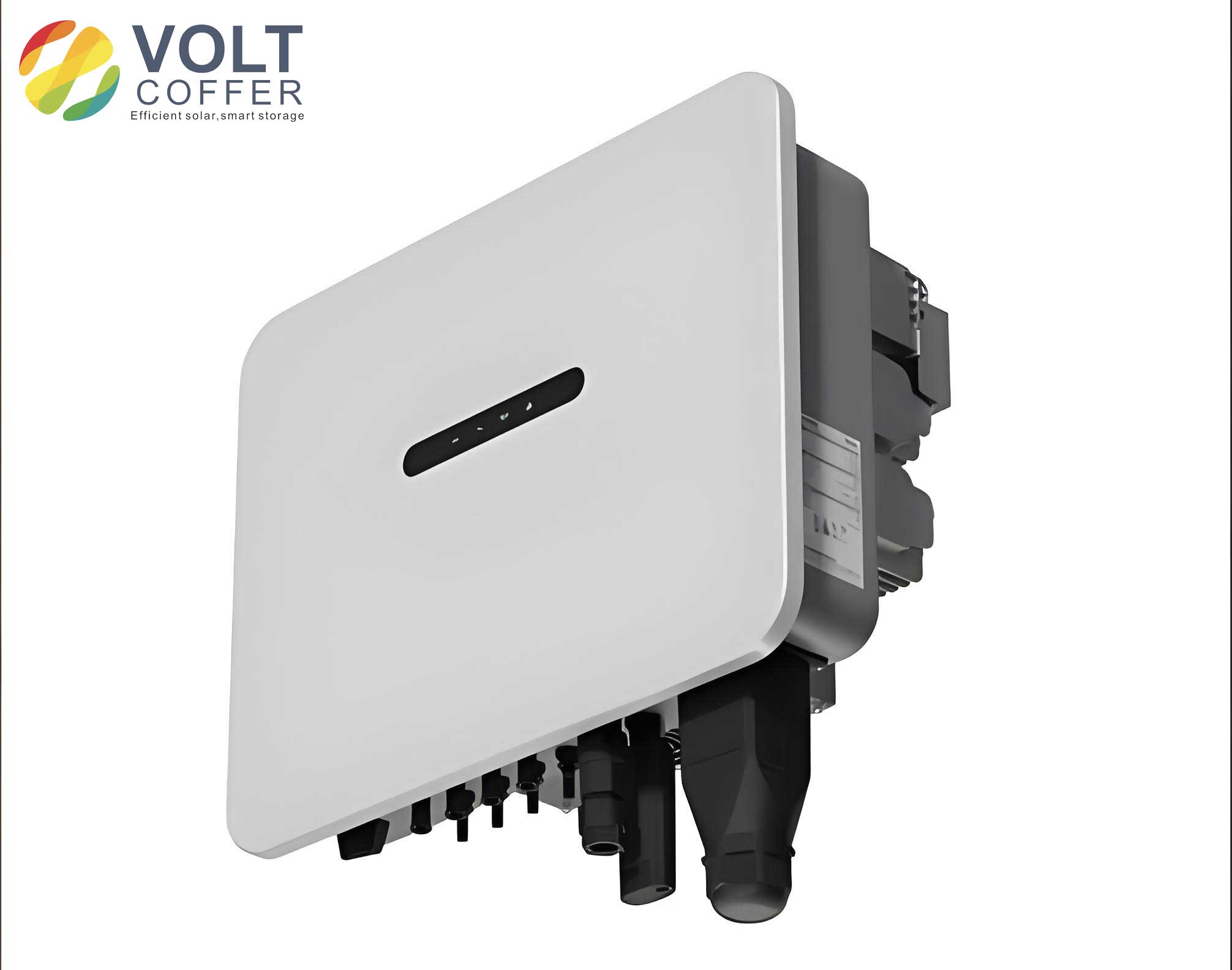
To address the limitations of linear control, nonlinear control techniques like backstepping have been explored for on-grid inverter control. Backstepping control offers a systematic, recursive design methodology that guarantees stability through the construction of a Lyapunov function. It can handle nonlinearities directly and provides a transparent way to shape the dynamic response. A direct PQ control strategy based on backstepping (PQ-BBC) has demonstrated superior performance in tracking speed and accuracy compared to PI-based methods, simplifying the control structure by eliminating inner current loops. However, existing backstepping designs for on-grid inverters typically assume an ideal, delay-free control environment. This work proposes an improved backstepping PQ control law explicitly designed to compensate for and ensure stability in the presence of significant and potentially time-varying delays inherent to the operation of a practical on-grid inverter.
Mathematical Model of the On-Grid Inverter
The foundation for controller design is an accurate dynamic model of the three-phase on-grid inverter. The system is typically represented in the synchronous rotating dq-reference frame, which transforms time-varying AC quantities into DC values for simplified control. Aligning the grid voltage vector with the d-axis simplifies the power equations. The standard voltage equations in the dq-frame are:
$$ v_d = Ri_d + L\frac{di_d}{dt} – \omega L i_q + e_d $$
$$ v_q = Ri_q + L\frac{di_q}{dt} + \omega L i_d + e_q $$
where \( v_d \) and \( v_q \) are the inverter output voltage components, \( i_d \) and \( i_q \) are the inverter output current components, \( e_d \) and \( e_q \) are the grid voltage components, \( R \) and \( L \) are the resistance and inductance of the output filter, and \( \omega \) is the grid angular frequency. With grid voltage orientation (\( e_d = V_g, e_q = 0 \)), the instantaneous active and reactive power outputs of the on-grid inverter are given by:
$$ P = \frac{3}{2} V_g i_d $$
$$ Q = -\frac{3}{2} V_g i_q $$
Substituting the current expressions from the power equations into the voltage equations, we can derive the power-state model of the on-grid inverter, which is more direct for PQ controller design:
$$ \frac{dP}{dt} = \frac{1}{L} \left( \frac{3}{2} v_d V_g – \frac{3}{2} V_g^2 – R P – \omega L Q \right) $$
$$ \frac{dQ}{dt} = -\frac{1}{L} \left( \frac{3}{2} v_q V_g + R Q – \omega L P \right) $$
This model explicitly shows the coupling between active and reactive power dynamics and forms the basis for the nonlinear controller development.
Impact of Time Delay on Conventional Backstepping Control (PQ-BBC)
The conventional backstepping PQ control (PQ-BBC) for an on-grid inverter is designed assuming instantaneous measurement and actuation. The controller is derived by defining power tracking errors \( e_P = P – P_{ref} \) and \( e_Q = Q – Q_{ref} \), and then constructing a control Lyapunov function to asymptotically drive these errors to zero. The resulting control laws are:
$$ v_d = \frac{2}{3V_g} \left( -L k_P e_P + R P + \omega L Q + L \dot{P}_{ref} \right) + V_g $$
$$ v_q = \frac{2}{3V_g} \left( L k_Q e_Q – R Q + \omega L P – L \dot{Q}_{ref} \right) $$
where \( k_P > 0 \) and \( k_Q > 0 \) are the controller gains. This controller provides excellent performance in a delay-free setting. However, in a real on-grid inverter, the measured powers \( P(t) \) and \( Q(t) \) used in the feedback law are actually delayed values \( P(t-\tau) \) and \( Q(t-\tau) \), where \( \tau \) represents the total loop delay. This transforms the system dynamics into a functional differential equation:
$$ \frac{dP}{dt} = f_P(v_d, P(t-\tau), Q(t-\tau)) $$
$$ \frac{dQ}{dt} = f_Q(v_q, P(t-\tau), Q(t-\tau)) $$
The presence of delay degrades performance, as illustrated in simulation studies. The table below summarizes key parameters used for analysis.
| Parameter | Symbol | Value |
|---|---|---|
| Grid Voltage (RMS) | \(V_g\) | 380 V |
| DC-Link Voltage | \(V_{dc}\) | 700 V |
| Filter Resistance | \(R\) | 0.2 Ω |
| Filter Inductance | \(L\) | 2 mH |
| Fundamental Frequency | \(f\) | 50 Hz |
| Sampling Period | \(T_s\) | 0.1 ms |
Simulating the on-grid inverter under PQ-BBC control with increasing constant delay \(\tau\) reveals clear detrimental effects. As \(\tau\) grows, the power response exhibits larger overshoot, longer settling time, and increased steady-state oscillation. Beyond a critical delay margin, the system becomes unstable. This underscores the necessity for a control design that explicitly incorporates the delay dynamics to enhance the robustness of the on-grid inverter.
Design of the Improved Backstepping PQ Controller with Time-Delay Compensation
To robustly manage the on-grid inverter in the presence of delays, we propose an improved backstepping control law. The core idea is to construct a Lyapunov-Krasovskii functional (LKF) candidate that includes integral terms accounting for the delayed state history. This allows the derivation of a control law that compensates for the destabilizing effect of the delay.
We begin by modeling the on-grid inverter dynamics with explicit delay terms \(\tau\):
$$ \frac{dP}{dt} = \frac{1}{L} \left( \frac{3}{2} v_d V_g – \frac{3}{2} V_g^2 – R P(t-\tau) – \omega L Q(t-\tau) \right) $$
$$ \frac{dQ}{dt} = -\frac{1}{L} \left( \frac{3}{2} v_q V_g + R Q(t-\tau) – \omega L P(t-\tau) \right) $$
Step 1: Active Power Controller Design. Define the active power tracking error \( e_1 = P – P_{ref} \). Consider a Lyapunov-Krasovskii functional candidate:
$$ V_1 = \frac{1}{2} e_1^2 + \int_{t-\tau}^{t} \phi_1(P(s), Q(s)) ds $$
where \( \phi_1 \) is a positive definite function to be designed. Its time derivative is:
$$ \dot{V}_1 = e_1 \dot{e}_1 + \phi_1(P(t), Q(t)) – \phi_1(P(t-\tau), Q(t-\tau)) $$
Substituting the delayed dynamics and strategically choosing \( \phi_1 \) to cancel the cross terms involving delayed states, we enforce \( \dot{V}_1 \leq -k_1 e_1^2 \) to guarantee stability. This leads to the improved control law for \( v_d \):
$$ v_d = \frac{2}{3V_g} \left[ -L k_1 e_1 + L \dot{P}_{ref} – \text{sgn}(e_1) \cdot |R P + \omega L Q| \right] + V_g $$
The signum function and absolute value term arise from the bounding technique used to handle the uncertain delayed-state terms in the stability proof, providing robustness.
Step 2: Reactive Power Controller Design. Similarly, define the reactive power error \( e_2 = Q – Q_{ref} \). Construct a composite Lyapunov-Krasovskii functional:
$$ V_2 = V_1 + \frac{1}{2} e_2^2 + \int_{t-\tau}^{t} \phi_2(P(s), Q(s)) ds $$
Following an analogous procedure, its derivative is rendered negative definite by designing the control law for \( v_q \):
$$ v_q = \frac{2}{3V_g} \left[ L k_2 e_2 + L \dot{Q}_{ref} + \text{sgn}(e_2) \cdot |R Q – \omega L P| \right] $$
where \( k_2 > 0 \). The final control structure for the on-grid inverter feeds the calculated \( v_d \) and \( v_q \) into the PWM module to generate the switching signals for the power semiconductors.
Simulation Analysis and Verification
The proposed improved backstepping controller and the conventional PQ-BBC were simulated in MATLAB/Simulink under various delay conditions to evaluate the performance of the on-grid inverter. Two scenarios were tested: step changes in power reference under constant delay and under time-varying delay. The controller gains were set equal for a fair comparison: \( k_P = k_Q = k_1 = k_2 = 150 \).
Scenario 1: Constant Delay. With a delay of \( \tau = 1 \) ms, the power reference steps from (10 kW, 200 Var) to (15 kW, 600 Var). The table below quantifies the performance comparison.
| Performance Metric | Conventional PQ-BBC | Proposed Controller |
|---|---|---|
| Active Power Overshoot | Significant (~18%) | Negligible (< 2%) |
| Settling Time (to within 2%) | > 50 ms | < 20 ms |
| Steady-State Error (P) | Oscillatory (~±30 W) | Zero |
| Steady-State Error (Q) | Oscillatory (~±15 Var) | Zero |
Scenario 2: Time-Varying Delay. With a delay modeled as \( \tau(t) = 1 \cdot \cos(t) \) ms, the reference steps down from (10 kW, 500 Var) to (5 kW, 200 Var). The proposed controller again demonstrates superior performance, maintaining stability and fast tracking with minimal oscillation, whereas the PQ-BBC exhibits pronounced and sustained power fluctuations.
Stability Margin Analysis. A key advantage of the proposed method is the enlargement of the delay margin—the maximum delay for which the on-grid inverter remains stable. The critical delay bounds were found through simulation sweeps.
| Delay Type | Stability Bound (PQ-BBC) | Stability Bound (Proposed) | Improvement |
|---|---|---|---|
| Constant Delay (\(\tau\)) | 5.58 ms | 7.52 ms | +34.8% |
| Time-Varying Delay (\(A\) in \(A\cos(t)\)) | 5.82 ms | 7.64 ms | +31.3% |
This significant increase in the allowable delay demonstrates the enhanced robustness of the proposed control strategy for the on-grid inverter.
Experimental Validation
The proposed controller was implemented on a hardware experimental platform featuring an on-grid inverter connected to a novel spiral spring energy storage system, a load which introduces significant and variable time delays. The system parameters matched the simulation setup. The power reference was stepped from (4 kW, 400 Var) to (8 kW, 800 Var). The experimental results conclusively validate the simulation findings. Compared to the PQ-BBC method, the proposed controller achieved:
- Superior Dynamic Response: The power settling time was reduced by approximately 50%.
- Enhanced Stability: The current waveform showed significantly reduced harmonic distortion and smoother transients.
- Accurate Steady-State Tracking: Zero steady-state error was maintained despite the presence of system delays and load interaction.
These results confirm the practical efficacy of the delay-compensating backstepping controller in managing a real on-grid inverter under challenging conditions.
Conclusion
This work has presented a comprehensive design and analysis of an improved backstepping PQ control strategy for on-grid inverters that explicitly accounts for time delays. The mathematical derivation, based on a Lyapunov-Krasovskii functional, yields a nonlinear control law that inherently compensates for the destabilizing effects of delays arising from sampling, computation, and communication in the on-grid inverter system. The proposed method directly addresses the core shortcomings of conventional backstepping and PI-based PQ control under delayed feedback.
Extensive simulation studies under both constant and time-varying delays demonstrate the superior performance of the proposed controller. Key achievements include the complete elimination of steady-state power error under normal delay conditions, a reduction of tracking error by over 50% near the stability boundary, a faster dynamic response, and a substantial increase (over 30%) in the system’s delay tolerance margin. These improvements directly translate to higher power quality, better grid support capability, and enhanced operational reliability of the on-grid inverter.
Experimental validation on a hardware testbed with a demanding energy storage load further corroborates the theoretical and simulation results, proving the practical viability and robustness of the approach. The proposed control strategy offers a valuable advanced solution for engineers seeking to deploy high-performance, delay-resilient on-grid inverters in modern power systems with significant penetration of renewable generation.