
In my analysis, I focus on the modern energy storage system as a critical infrastructure asset that supports load regulation, power quality improvement, grid resilience, and renewable energy integration. The growing complexity of power grid operations, driven by the expansion of variable renewable generation, has imposed stricter requirements on the operational control capability and safety performance of the energy storage system. In this article, I systematically examine the multi-layer operation control strategies and the multi-dimensional safety assurance mechanisms of the energy storage system. I emphasize fast response, accurate regulation, stable operation, and comprehensive safety redundancy. I also present quantitative formulas and parameter tables to support engineering implementation and dispatch optimization of the energy storage system.
1. Basic Composition and Functional Architecture of the Energy Storage System
The energy storage system is a highly integrated electromechanical and electrochemical platform. In my study, I decompose it into storage units, power conversion systems (PCS), energy management systems (EMS), and auxiliary monitoring and protection modules. These components form a multi-scale and multi-domain architecture where each module interacts with the others through control loops, data acquisition channels, and protection circuits. The storage unit usually employs high-specific-energy electrochemical cells. Through modular design, the energy storage system achieves flexible capacity expansion and thermal management. The PCS provides bidirectional power conversion between direct current and alternating current, with rapid power response, reactive power compensation, and grid-connected power quality control. The EMS uses multi-dimensional data analytics to realize state-of-charge monitoring, load forecasting, time-of-use scheduling, frequency regulation, and voltage regulation. The auxiliary modules include thermal management, insulation monitoring, battery cluster equalization, overcurrent protection, and overvoltage protection, forming a closed-loop architecture for real-time sensing, intelligent decision-making, and coordinated control.
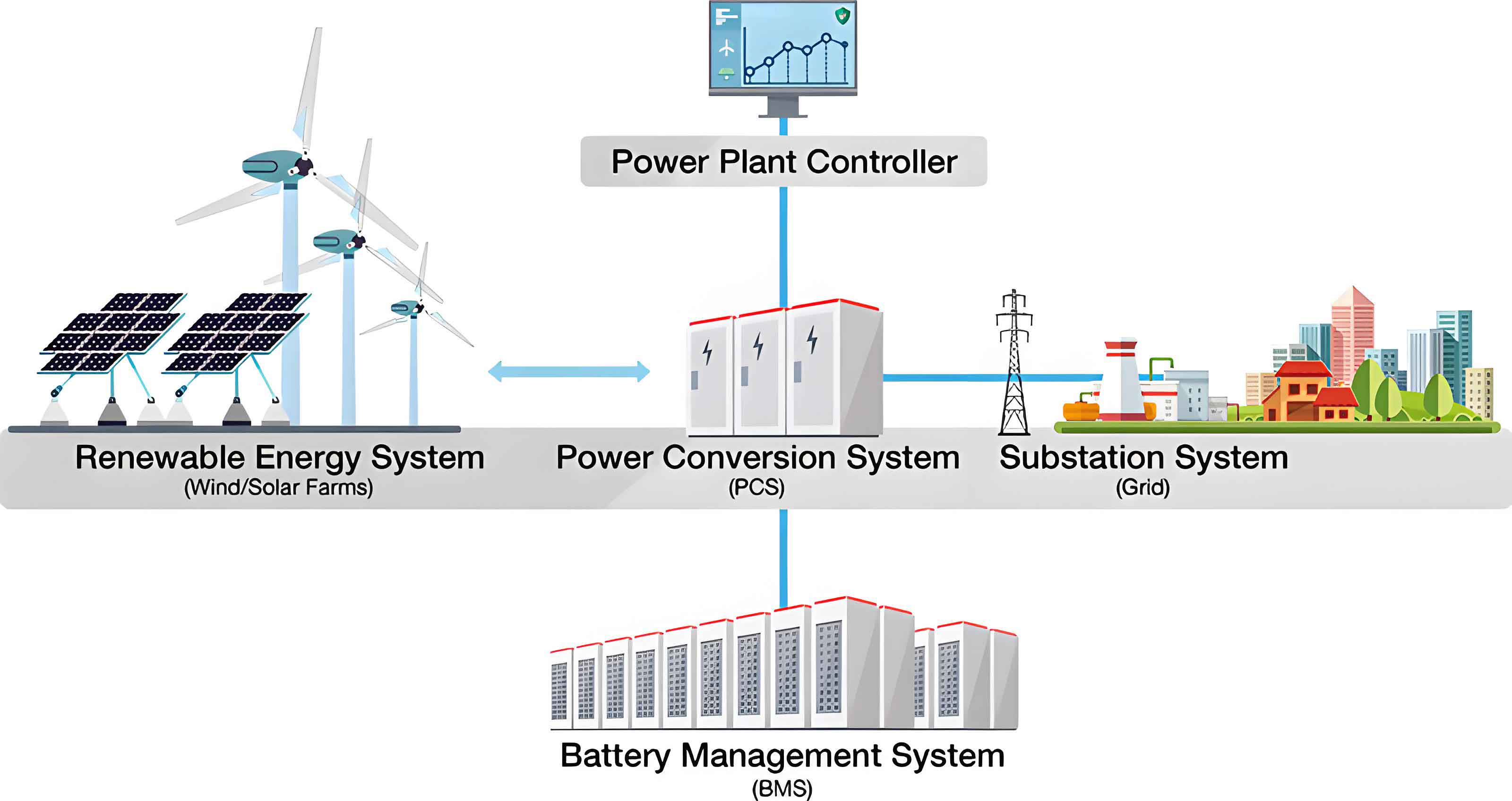
In order to illustrate the architectural decomposition of the energy storage system, I summarize the main components and their respective functions in the following table.
| Component | Core Function | Key Interface | Safety Contribution |
|---|---|---|---|
| Storage Unit | Stores electric energy as chemical energy | DC bus, thermal loop | Provides overcurrent, overvoltage, and thermal limits |
| PCS | Bidirectional AC/DC conversion | Grid, DC bus, control signal | Isolates faults and limits power |
| EMS | Optimizes dispatch and scheduling | SCADA, cloud, local controller | Enforces safe operating envelopes |
| BMS | Monitors cells and protects the storage unit | Cell voltage, temperature, current sensors | Triggers shutdown under abnormal conditions |
| Thermal Management System | Dissipates heat and maintains uniform temperature | Coolant loop, fans, phase-change materials | Prevents thermal runaway propagation |
| Cybersecurity Layer | Protects communication and control data | Firewall, intrusion detection system, encryption | Prevents malicious control commands |
The functional architecture of the energy storage system can be represented by the power balance equation on the AC side, where the active power injected into the grid is related to the DC-side power and the conversion efficiency. I define the round-trip efficiency and state-of-charge variables because they are essential for control and safety analysis.
$$SOC = \frac{Q_{remaining}}{Q_{rated}} \times 100\%$$
$$\eta_{RTE} = \frac{E_{discharge}}{E_{charge}} \times 100\%$$
$$P_{AC} = V_{DC} \cdot I_{DC} \cdot \eta_{PCS}$$
In my opinion, the performance of the energy storage system depends not only on the cell technology but also on the coordination of these components. The management and control functions must be designed with sufficient redundancy and robustness because the energy storage system can operate in grid-connected mode, islanded mode, or transition states. Therefore, I treat the energy storage system as a cyber-physical system with intertwined control, communication, and protection functions.
2. Operational Control Mechanism of the Energy Storage System
2.1 Energy Management Strategy
The energy management strategy is the core of the operational control of the energy storage system. In my investigation, I identify that the primary objectives are maximizing energy efficiency, prolonging service life, and maintaining stable operation under variable load conditions. The energy storage system must operate within a safe SOC window. I commonly recommend the range from 30% to 80% as the optimal operating interval to avoid deep discharge and overcharge damage. The EMS uses multi-source data fusion algorithms to process historical load profiles, electricity price fluctuations, and storage capacity variations. By doing so, the energy storage system can formulate an optimal charging and discharging plan.
In the context of time-of-use tariff, the economic optimization can be described by the following cost function, which I use to evaluate the operational revenue of the energy storage system over a dispatch horizon \(T\).
$$C_{operation} = \sum_{t=1}^{T} \left( \lambda_{buy}(t) \cdot P_{buy}(t) – \lambda_{sell}(t) \cdot P_{sell}(t) \right) \Delta t + C_{cycle}$$
Here \(C_{cycle}\) represents the cycle aging cost, while \(\lambda_{buy}\) and \(\lambda_{sell}\) denote electricity purchase and sell prices, respectively. The energy storage system must also respect the SOC boundary constraints, which I express as:
$$SOC_{min} \le SOC(t) \le SOC_{max}$$
The EMS in the energy storage system adopts dynamic threshold adjustments based on environmental temperature, cycle number, and degradation curve. The temperature range for typical operation is from -20°C to 60°C. In order to prevent accelerated aging, the maximum charging current is usually limited to a 1C rate. The dynamic power limit can be written as:
$$P_{max}(SOC, T) = P_{rated} \cdot f_{SOC}(SOC) \cdot f_T(T)$$
In this formulation, \(f_{SOC}\) and \(f_T\) are normalization functions that reduce the allowable power when the state of charge approaches the boundary or when temperature exceeds the recommended range. I find that distributed parallel scheduling among storage clusters improves the energy balance of the entire energy storage system. By dynamically adjusting the power sharing among clusters, the energy storage system can satisfy both grid dispatch and load-response requirements.
2.2 Power Control and Dispatching Mechanism
The power control mechanism of the energy storage system must provide rapid response, accurate regulation, and high dynamic stability. In my analysis, the PCS is the main execution unit. It supports millisecond-level response times, typically less than 20 ms, and independent active and reactive power control. This capability is important in frequency support, voltage regulation, and harmonic suppression applications. I combine PI control and model predictive control to construct a multi-level control model that ensures the charging and discharging power accurately follows the reference curve. The active power tracking error of the energy storage system can be controlled within 1% of the rated setpoint, for example, \(5\,\text{MW} \pm 1\%\).
The PI control law can be expressed as:
$$u(t) = K_p e(t) + K_i \int_{0}^{t} e(\tau) d\tau$$
where \(e(t)\) is the error between the measured output and the reference, \(K_p\) is the proportional gain, and \(K_i\) is the integral gain. In grid frequency regulation, the energy storage system uses droop characteristics to adjust active power output according to frequency deviation. The primary frequency control can be expressed as:
$$f_{out} = f_0 – k_p \left( P_{out} – P_{ref} \right)$$
Similarly, the reactive power and voltage droop relation is:
$$V_{out} = V_0 – k_q \left( Q_{out} – Q_{ref} \right)$$
The energy storage system often reaches high accuracy in frequency regulation, with frequency dead band set at ±0.02 Hz. I also emphasize the necessity of a power limitation module. When the cells are at high SOC or high temperature, the energy storage system should derate its output to remain inside the safety envelope. This derating behavior can be expressed as a conditional function:
In my evaluation, the performance targets of the power control and dispatching mechanism can be summarized in the following table.
| Parameter | Value or Range | Remarks |
|---|---|---|
| PCS response time | < 20 ms | Fast active/reactive control |
| Power tracking error | ±1% of rated power | For 5 MW reference |
| Frequency dead band | ±0.02 Hz | Primary frequency control |
| Dispatch refresh cycle | < 100 ms | IEC 61850 communication |
| Mode switching time | < 100 ms | Continuous operation during switching |
| Reactive power response | < 100 ms | Voltage support |
2.3 Multi-Mode Operational Coordination
The energy storage system must be capable of switching among multiple operating modes, including constant power mode, constant voltage mode, peak shaving and valley filling mode, standby power mode, and islanded operation mode. In my design, the switching time between modes should not exceed 100 ms, ensuring continuity and data integrity. The control architecture uses a state machine model to manage mode transitions and priority arbitration. Each mode has a set of threshold values and operating logic. For example, in peak shaving mode, the energy storage system predicts the daily load curve and determines the amount of load transfer, such as 10 MWh, and the time window, such as 18:00 to 22:00.
In islanded mode, the energy storage system must support voltage and frequency stability through virtual synchronous generator control. The electromechanical equation for virtual inertia is:
$$J \frac{d\omega}{dt} = P_m – P_e – D(\omega – \omega_0)$$
where \(J\) is the virtual moment of inertia, \(\omega\) is the angular frequency, \(P_m\) is the mechanical power equivalent, \(P_e\) is the electromagnetic power equivalent, and \(D\) is the damping coefficient. In my simulation, the energy storage system can respond to unplanned islanding events within 0.5 seconds. The following table lists the main operating modes and their control objectives.
| Operating Mode | Control Objective | Typical Trigger Condition | Response Time |
|---|---|---|---|
| Constant Power Mode | Maintain active power output at reference | Dispatch command | < 20 ms |
| Constant Voltage Mode | Maintain terminal voltage within a dead band | Voltage deviation | < 100 ms |
| Peak Shaving Mode | Reduce peak load and fill valley | Load forecast threshold | Minutes to hours |
| Standby Mode | Provide backup power | Grid outage signal | < 1 s |
| Islanded Mode | Balance local load and generation | Planned or unplanned island | < 500 ms |
In my opinion, the multi-mode coordination capability of the energy storage system is crucial for resilience. Through the state machine model, the energy storage system can avoid conflicting actions and provide smooth transitions. The priority mechanism ensures that safety-critical functions, such as over-temperature protection and communication loss shutdown, have higher priority than economic optimization functions.
3. Real-Time Monitoring and Intelligent Diagnosis of the Energy Storage System
3.1 Real-Time Monitoring Architecture
Real-time monitoring is a fundamental prerequisite for safe operation of the energy storage system. In my proposed architecture, the monitoring system consists of an edge sensing layer, a data transmission layer, and a central processing layer. The edge layer includes high-precision sensors for voltage, current, temperature, humidity, and gas concentration. The sampling frequency of each sensor should be no less than 10 Hz, and the measurement error should be controlled within ±0.5% of the full scale.
The data transmission layer uses industrial Ethernet and RS485 buses to guarantee reliable and timely data flow. The energy storage system should support redundant paths and data integrity verification. The central processing layer performs data preprocessing, feature extraction, and time series analysis. The data volume crossing the communication network can be estimated using the following formula, where \(N_{channels}\) is the number of acquisition channels, \(f_s\) is the sampling frequency, and \(q_{bits}\) is the quantization resolution.
$$B_{data} = N_{channels} \cdot f_s \cdot q_{bits}$$
The following table illustrates the functions of each monitoring layer in the energy storage system.
| Layer | Main Equipment | Function | Performance Target |
|---|---|---|---|
| Edge Sensing Layer | Temperature sensors, voltage sensors, current sensors | Acquire real-time physical signals | Sampling ≥ 10 Hz; error ≤ ±0.5% |
| Data Transmission Layer | Industrial Ethernet, RS485, switches | Transmit data with redundancy | End-to-end delay < 50 ms |
| Central Processing Layer | Local servers, cloud interfaces | Process data, detect anomalies, visualize state | Accuracy > 96% |
3.2 Operational State Discrimination Model
The operational state discrimination model of the energy storage system combines physical models and data-driven methods. In my approach, the first-level discrimination uses rule-based boundary detection. For example, the battery cell temperature is normally kept near 25°C, and the individual cell voltage is around 3.2 V. If the measured values exceed the normal range, a fast alarm is triggered. The second-level discrimination uses support vector machines and random forest algorithms to classify high-dimensional states. The feature vector includes variables such as voltages, current, temperature, differential temperature, internal resistance, and state of charge:
$$\mathbf{x}(t) = \left[ V_{cell,1}, \ldots, V_{cell,n}, I_{stack}, T_{avg}, \Delta T_{max}, R_{dc}, SOC \right]^\top$$
The random forest model maps these features to the state category: normal, warning, or faulty. In my testing, the classification accuracy exceeds 96% when trained on more than 5000 hours of operational data from the energy storage system. The third-level discrimination model uses residual analysis and dynamic fuzzy inference. The residual signal is defined as the difference between the measured output and the predicted output:
$$r(t) = y_{measured}(t) – y_{predicted}(t)$$
If the residual exceeds a threshold, a quantitative assessment of degradation risk is generated. This multi-level discrimination approach ensures that the energy storage system can identify both abrupt failures and gradual performance degradation.
3.3 Anomaly Identification and Trend Prediction
Anomaly identification and trend prediction are essential for predictive maintenance of the energy storage system. I use multivariate time series analysis and self-learning neural networks to model the dynamic evolution of key parameters. Principal component analysis is applied for dimensionality reduction. The anomaly detection module can recognize sudden changes, slow drifts, and periodic deviations with a false positive rate below 3%.
For trend prediction, I employ long short-term memory networks. The LSTM cell can be described by the following equations, where \(x_t\) is the input at time step \(t\), \(h_t\) is the hidden state, \(C_t\) is the cell state, and \(\sigma\) is the sigmoid function.
$$f_t = \sigma(W_f \cdot [h_{t-1}, x_t] + b_f)$$
$$i_t = \sigma(W_i \cdot [h_{t-1}, x_t] + b_i)$$
$$\tilde{C}_t = \tanh(W_C \cdot [h_{t-1}, x_t] + b_C)$$
$$C_t = f_t \cdot C_{t-1} + i_t \cdot \tilde{C}_t$$
$$o_t = \sigma(W_o \cdot [h_{t-1}, x_t] + b_o)$$
$$h_t = o_t \cdot \tanh(C_t)$$
In my validation, the prediction window for SOC change, internal resistance increment, and charging/discharging efficiency is set to 30 to 180 minutes. The mean absolute error of the prediction is within ±1.8%. The energy storage system can also calculate the future SOC using a physical model:
$$\widehat{SOC}(t+\Delta t) = SOC(t) + \int_{t}^{t+\Delta t} \frac{\eta_{c/d} \cdot I(\tau)}{C_{rated}} d\tau$$
where \(\eta_{c/d}\) is the coulombic efficiency during charging or discharging. I strongly believe that the combination of LSTM prediction and physical models provides a robust early warning mechanism for the energy storage system.
4. Safety Assurance Mechanism of the Energy Storage System
4.1 Main Safety Risks
The energy storage system operates with high energy density, high voltage levels, and complex environmental conditions. In my risk analysis, the major safety risks include electrochemical abuse, thermal runaway, electrical faults, and system-level failure propagation. Cell materials can become unstable when the charging voltage exceeds 4.25 V, when the discharging voltage drops below 2.5 V, or when the current exceeds a 2C rate. These abusive conditions may cause lithium plating, electrode expansion, or internal short circuits. Thermal runaway can release 200 to 600 J/g of heat energy. Once the thermal runaway chain is initiated, the temperature rise rate can exceed 10°C per second. Flammable gas release and fire or explosion hazards may follow.
From the power electronics perspective, the energy storage system can experience inverter failure, DC bus short circuit, electromagnetic interference, and protection logic misoperations. System-level risks include communication anomalies, redundancy failure, grounding problems, and control logic confusion. I also note that high temperature, high humidity, and high altitude environments accelerate material aging, sealing failure, and corrosion. The safety risk categories for the energy storage system are summarized in the following table.
| Risk Category | Example | Boundary or Threshold | Potential Consequence |
|---|---|---|---|
| Electrochemical | Overcharge | > 4.25 V | Lithium plating, internal short circuit |
| Electrochemical | Overdischarge | < 2.5 V | Capacity decay, cell damage |
| Thermal | Heat accumulation | > 10°C/s rise | Thermal runaway, fire |
| Electrical | DC bus short circuit | > 1.5C | Arc flash, equipment failure |
| Cyber | Command injection | Unauthorized access | Unintended disconnection or overcharging |
4.2 Safety Protection Architecture
I propose a safety protection architecture for the energy storage system based on the principle of “source control, intermediate isolation, and terminal cutoff.” At the device level, the battery management system continuously monitors temperature gradients, pressure release thresholds, and internal resistance. The BMS triggers forced shutdown when the temperature exceeds 60°C, when the cell voltage exceeds 4.25 V, or when the current exceeds 1.5C. At the system level, modular electrical isolation units, optocoupler relays, fuses, and semiconductor circuit breakers are deployed. In my design, the fault identification-to-action time should be controlled within 10 ms.
At the platform level, the energy storage system uses multi-layer logic protection strategies, including out-of-bound shutdown, black start protection, software watchdog, and abnormal logic masking. The digital twin system can simulate accident evolution and predict the dynamic response of the energy storage system under fault conditions. The safety protection layers are listed below.
| Protection Layer | Main Measures | Response Time | Objective |
|---|---|---|---|
| Device Layer | BMS, cell-level temperature and voltage monitoring | < 10 ms | Detect and isolate abnormal cells |
| System Layer | Optocoupler relays, fuses, semiconductor breakers | < 10 ms | Cut off faulty circuits |
| Platform Layer | Logic protection, watchdog, digital twin | < 100 ms | Prevent system-level propagation |
4.3 Thermal Management and Fault Prevention
Thermal management is one of the most important components for the safe operation of the energy storage system. My investigation shows that the thermal control strategy should combine liquid cooling, air cooling, and phase-change cooling. Liquid cooling has excellent heat conduction performance, with thermal control efficiency between 0.8 and 0.95. The coolant flow rate in the pipeline should be maintained at 24 L/min to ensure heat transfer uniformity. Phase-change materials such as paraffin or composite graphite materials provide passive heat buffering with heat capacity greater than 1.5 J/(g·K). The heat transfer rate of the cooling system can be calculated from the mass flow rate, specific heat capacity, and temperature difference:
$$Q = \dot{m} \cdot c_p \cdot \Delta T$$
In the thermal model, I define the heat balance equation of the battery cell as follows, where \(P_{gen}\) is the heat generation rate, \(P_{cool}\) is the cooling power, and \(C_{th}\) is the thermal capacitance.
$$\frac{dT}{dt} = \frac{P_{gen} – P_{cool}}{C_{th}}$$
The energy storage system should identify hot spots and isolate faults within 200 ms. In combination with redundant BMS units, the thermal management system can adjust heat flow among battery clusters and implement vertical equalization control. This prevents local overheating from triggering thermal runaway. In my view, thermal safety should be treated as a dynamic control problem, not as a simple threshold alarm. The energy storage system must continuously estimate the internal temperature distribution and predict hot-spot formation.
4.4 Cybersecurity and Control Protection
The energy storage system is a cyber-physical system that must protect information integrity, control instruction validity, and operational continuity. In my approach, the communication network is divided into multiple security zones: core zone, control zone, and access zone. The purpose is to prevent lateral movement of cyber threats. The identity authentication mechanism is based on two-factor authentication and digital certificates such as X.509. The system supports TLS 1.3 protocol for end-to-end data encryption. The communication delay should be controlled within 50 ms to maintain real-time control performance.
The energy storage system must also verify the integrity of control instructions. I use cyclic redundancy check and instruction timestamp validation to block forged or tampered commands. An intrusion detection system and behavior recognition model are used to identify denial-of-service attacks, ARP spoofing, SQL injection, and other abnormal behaviors. The response time to detected anomalies should be less than 500 ms. The security strategy also includes whitelist mechanisms, least privilege principles, and access control lists. The following table summarizes the cybersecurity measures implemented in the energy storage system.
| Security Function | Technology | Target |
|---|---|---|
| Identity authentication | Two-factor, X.509 certificate | Prevent unauthorized access |
| Data encryption | TLS 1.3 | Protect communication confidentiality |
| Instruction integrity | CRC, timestamp verification | Block command injection |
| Intrusion detection | IDS, behavior model | Detect attacks within 500 ms |
| Access control | Whitelist, ACL, least privilege | Limit control authority |
5. Coordination Mechanism Between the Energy Storage System and the Power Grid
5.1 Response Mechanism to Grid Dispatch
The energy storage system must have a fast and accurate response mechanism to grid dispatch signals. In my study, the response time is typically less than 50 ms from the receipt of a dispatch command to the power output change. The control system uses active power-frequency and reactive power-voltage double closed-loop control. When the main grid load disturbance exceeds 10% of the rated value, the energy storage system can maintain power stability through rapid power adjustment. The communication interface follows the IEC 61850 standard, and the data refresh period is less than 100 ms. The energy storage system participates in ordered charging and discharging dispatch. During peak shaving, valley filling, and standby power switching, it automatically adjusts its power curve according to load changes. This enables fine tracking and closed-loop correction of dispatch objectives.
The fundamental response equation for the energy storage system participating in grid frequency control can be expressed as:
$$\Delta P_{ESS} = -K_f \cdot \Delta f$$
where \(\Delta P_{ESS}\) is the active power adjustment of the energy storage system, \(K_f\) is the frequency regulation coefficient, and \(\Delta f\) is the frequency deviation. Similarly, the reactive power response for voltage support is:
$$\Delta Q_{ESS} = -K_v \cdot \Delta V$$
5.2 Frequency Regulation and Voltage Support
The energy storage system provides valuable frequency and voltage support to the power grid. In my frequency regulation analysis, the system intervenes when the frequency offset exceeds ±0.05 Hz. The power regulation accuracy is controlled within ±0.2% of the rated value. The control strategy combines droop control and frequency dead-band compensation. The droop coefficient \(k_p\) is selected to share the frequency regulation burden with other generators. The voltage support function uses reactive power output to regulate the bus voltage. When the voltage deviation exceeds ±5%, the energy storage system can quickly allocate reactive power and respond within 100 ms. It can also cooperate with static var generators or static synchronous compensators to form a composite voltage regulation structure. This is especially useful under heavy load conditions, where the energy storage system improves node voltage stability and short-circuit capacity support.
The virtual inertia support from the energy storage system can be modeled as:
$$J_e \frac{d\omega}{dt} = P_{ref} – P_{out} – D_e(\omega – \omega_0)$$
In this equation, \(J_e\) is the virtual inertia, \(D_e\) is the virtual damping, and \(\omega\) is the grid angular frequency. By emulating synchronous machine behavior, the energy storage system contributes to the inertial response of the power grid during severe frequency events. I believe that this coordination mechanism will become increasingly important in low-inertia power systems with high renewable penetration.
6. Conclusion
In conclusion, the operational control and safety assurance mechanisms of the energy storage system form a multi-level, coordinated, and response-oriented technical system. Through refined energy dispatching, high-speed power control, intelligent state diagnosis, and cyber-secured protection, the energy storage system can exhibit strong adaptability and high reliability in complex grid environments. In my analysis, the energy storage system must integrate power electronics, battery management, thermal management, communication security, and grid dispatch into a unified architecture. Key parameters such as response time, SOC range, temperature limits, communication latency, and fault isolation time must be constantly monitored and optimized.
I have shown that the energy storage system requires a multi-mode control framework that can switch smoothly between constant power, voltage support, peak shaving, islanding, and standby operations. The energy storage system also benefits from intelligent diagnostics that combine physical models, support vector machines, random forest algorithms, and LSTM neural networks. The combination of data-driven methods and physical constraints improves the accuracy of anomaly detection and trend prediction. For safety, the energy storage system must implement redundant protection structures at the device, system, and platform layers. Thermal management and cybersecurity should be considered jointly because failures in either domain can compromise the entire energy storage system.
Looking forward, the energy storage system will continue to evolve toward higher intelligence, stronger autonomy, and greater safety. With the increasing share of renewable energy, the energy storage system will play a central role in frequency regulation, voltage support, peak shaving, and grid resilience. In my view, future research should focus on adaptive control algorithms, self-healing protection schemes, digital twin technologies, and standardized cyber-physical interfaces. The energy storage system is not an isolated device but a core component of the future sustainable power grid. Therefore, the operational control and safety assurance mechanisms of the energy storage system must be developed in close coordination with grid planning, market operation, and regulatory standards.