
Double fed induction generator (DFIG) is a mainstream wind power generation model. As of 2019, the installed capacity of this model accounts for 80% of wind turbines. DFIG has the advantages of low output harmonic content, high wind energy utilization rate, and small inverter capacity. However, a high proportion of wind turbines can easily cause frequency stability issues in the power grid. The main reasons for frequency instability can be attributed to:
(1) The wind turbine operates synchronously with the grid frequency through power electronic devices, and there is no coupling relationship between the rotor speed of the unit and the grid frequency.
(2) The unit operates at the maximum power point to increase wind energy utilization, but lacks the ability to provide active power backup for primary frequency regulation. With the increase of wind power penetration rate and the expansion of wind farm scale, the pressure of frequency regulation increases sharply.
To effectively reduce the frequency regulation pressure of traditional wind turbines, it is necessary to construct a new control strategy to enable wind turbines to have excellent frequency regulation performance. The existing frequency regulation strategies for wind turbines include rotor inertia, overspeed, pitch control, and combination control. These strategies add coupling modules between the grid frequency and the active power output of the wind turbine, so that the asynchronous wind turbine meets the rotor motion equation of the synchronous generator, achieving real-time adjustment of the unit’s active power to the grid frequency changes. This type of method has successfully solved the frequency regulation problem under specific wind speeds, but there are certain shortcomings. For example, the time domain of rotor inertia control is relatively short; Overspeed and pitch control reduce the efficiency of wind turbine power generation by reserving active power reserves for grid frequency regulation; The execution process of combination control is complex and lacks robustness. Energy storage batteries, as important devices for auxiliary voltage regulation, peak shaving, and smooth active power, have the characteristics of good anti-interference, high energy density, and strong control flexibility. Equipping energy storage batteries and designing a wind storage joint frequency regulation strategy when participating in wind turbines or wind farms is more advantageous than simply changing the wind turbine control strategy for frequency regulation. Wind storage collaborative control ensures the efficiency of wind turbine power generation while also taking into account execution efficiency. For example, through coordinated control of the kinetic energy of the battery and rotor, short-term inertia support of the power grid frequency under different wind speeds has been achieved. By using model predictive control to establish a frequency regulation model for a wind storage combined electric field, the pitch angle is corrected based on the deviation between the wind turbine active power reference value and the actual value, achieving secondary frequency regulation of the power grid. By using fuzzy rules to modify the energy storage active output of wind farms, the results show that the frequency regulation effect of this strategy is significantly better than that of synchronous generators of equal capacity. It is proposed to use virtual droop, virtual inertia control, and negative inertia control based on the frequency range, and construct inertia coefficient and droop coefficient based on the battery state of charge, taking into account the robustness of frequency regulation and the effectiveness of energy maintenance. There have been studies on the impact of energy storage and wind storage frequency regulation control strategies on the frequency regulation performance of the power grid, but it has not been considered that energy storage frequency regulation or wind storage frequency regulation will lead to higher frequency regulation power and cost; Insufficient frequency modulation power will cause frequency instability issues.
In fact, as an AC/DC conversion device between energy storage batteries and the power grid, the inverter can also simulate the frequency modulation characteristics of synchronous machines using the VSG strategy. To address the frequency regulation problem of power grids with high proportion of power electronic devices, an extended VSG strategy is proposed for high uncertainty generation and severe load fluctuations, which adjusts and optimizes parameters through robust control. Aiming to shorten the transient response time, a method for selecting stage inertia and damping coefficient is proposed by constraining the frequency and rate of change to be lower than the preset values. Set the virtual inertia in VSG as a function of frequency change, and calculate the frequency tracking coefficient, rotational inertia, and damping constant through tuning. Using an adaptive droop strategy to adjust the frequency of the power grid, more/less unbalanced active power is allocated to VSGs with smaller/larger frequency deviations. Consider the microgrid of wind turbines, photovoltaic arrays, and electric vehicle clusters, coordinate multiple virtual synchronous machines with conventional control to compensate for active power shortages. Using frequency integration to eliminate the frequency deviation of microgrids and improving the frequency modulation capability of VSGs by proportionally distributing power. By adopting a zero start boosting method and adopting a VSG control strategy during microgrid black start, the problem of black start failure caused by switching control methods is overcome; It is proposed to use VSG control to achieve parallel operation of multiple energy storage systems, and a voltage regulation and frequency regulation control strategy for energy storage assisted gas turbine black start is designed. Reference [26] applies the VSG control strategy to the grid connection of photovoltaic storage, which satisfies the synchronous machine characteristic equation of the photovoltaic storage module and significantly suppresses the fluctuation of photovoltaic output. Reference [27] proposes a dynamic adjustment control strategy for the rotational inertia of virtual synchronous machines, which adopts a larger rotational inertia when the frequency begins to change, aiming to reduce the frequency change rate; At frequency
During the recovery period, a smaller moment of inertia is used to accelerate the frequency recovery of the power grid. Previous literature has studied the frequency modulation response capability of VSG strategy on microgrids, ignoring the issues of excessive and rapid frequency changes in the power grid, inability of VSG control to ensure good frequency response, and excessive frequency offset and rate of change.
Equipping energy storage batteries on the DC side of DFIG can utilize GSC to provide power channels. In order to utilize the frequency modulation performance of energy storage and further improve and utilize the frequency modulation characteristics of VSG to reduce grid frequency deviation and frequency change rate, this paper proposes that energy storage batteries considering dynamic frequency inertia characteristics participate in grid primary frequency modulation control. The main contributions include:
(1) To utilize the inertia support ability and primary regulation ability of energy storage batteries on the power grid, an additional active power module is constructed. The virtual inertia of energy storage batteries and the active power generated by the droop control strategy are used as additional power for variable rotor inertia control and output feedback model predictive control, respectively.
(2) Construct a variable rotor inertia that takes into account system frequency deviation and rate of change, and then propose a variable rotor inertia control strategy to achieve real-time adjustment of the system frequency by the rotor inertia.
(3) Propose an output feedback model predictive control strategy, which dynamically predicts and compensates for system frequency deviation by establishing a feedback channel between the rotor angular frequency increment and torque increment.
1. Design of frequency modulation control strategy for energy storage batteries
When configuring energy storage batteries on the DC side of DFIG, the grid side converter of wind turbines can serve as the power channel for energy storage batteries to participate in grid frequency regulation. The use of VSG control in the grid side inverter can effectively utilize the inertia response and primary frequency regulation capability of the inverter. Therefore, it is necessary to analyze and explore the frequency modulation characteristics of energy storage batteries and the VSG control strategy of GSC.
1.1 Analysis of primary frequency regulation control for energy storage batteries
The primary frequency regulation control strategy of energy storage batteries can be divided into virtual inertia control and droop control. Virtual inertia control aims to adjust the dynamic characteristics of the system frequency, while droop control is beneficial for improving the steady-state performance of the frequency. By utilizing the complementary characteristics of the two, the primary frequency modulation characteristics of the system can be effectively improved. When the frequency deviation is large, the virtual inertia control strategy can utilize the advantages of fast response speed and good tracking performance of energy storage batteries, which can not only reduce the transient frequency deviation of the system, but also greatly prevent frequency degradation and accelerate system frequency recovery. When the frequency deviation is small, only virtual inertial control is used for regulation. Due to measurement errors and other reasons, steady-state frequency deviation will be caused, leading to an increase in the output of the energy storage battery, which in turn triggers over action or even misoperation of the energy storage battery. By cooperating with virtual droop control, it can avoid significant charging and discharging of the energy storage battery and improve its steady-state effect.
1.2 Additional active power module
To utilize the primary frequency regulation and inertia response capabilities of energy storage batteries. The additional active power module of GSC is designed as two parts: droop control of energy storage batteries and virtual inertia. The control strategy in this article does not require modification of the rotor side converter control strategy. On the one hand, additional droop power is obtained through the droop control of the energy storage battery Δ Pdroop_ 1. Provide correction for the reference value of active power predicted by the output feedback model; On the one hand, obtaining additional inertia power based on the differential of frequency deviation Δ Pinertia_ 2. Provide correction for the active reference value of variable rotor inertia control.
The additional active power of GSC can be written as:
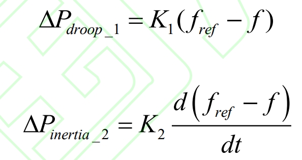
In the formula, K1 represents the sag coefficient of the energy storage battery, K2 represents the virtual inertia coefficient of the energy storage battery, and f and fref represent the measured frequency and rated frequency of the system, respectively.
1.3 Frequency modulation indicators
Different frequency modulation indicators are adopted for the frequency response characteristics under wind speed and different load disturbances.
For the frequency response of step load and wind speed, the maximum frequency deviation is adopted Δ Fmax, steady-state frequency deviation Δ Fsteady, maximum output power of wind power Δ Pgemax and initial frequency drop velocity dfinitial are used as frequency modulation indicators. Δ Fdymax and Δ The smaller the fsteady, the better the frequency modulation effect; Δ The larger the Pgemax, the higher the power generation efficiency of the wind turbine. For the frequency response of random loads, add the maximum peak valley difference of the new frequency Δ Fpvmax, peak valley difference of maximum output power of wind power Δ Ppvmax is used as a frequency modulation indicator. Δ The smaller the fpvmax, the better the frequency modulation effect; Δ The larger the Ppvmax, the higher the power generation efficiency of wind turbines.
2. Variable rotor inertia and output feedback model predictive control of VSG
Relying solely on virtual inertia control and droop control of energy storage batteries can easily lead to insufficient inertia response capability and significant frequency deviation of the power grid. To improve the inertia response capability of wind turbines and reduce the maximum frequency deviation of the system, this paper proposes an improved VSG control strategy, which consists of variable rotor inertia control and output feedback model predictive control.
2.1 Variable rotor inertia control
By using virtual synchronous generator control, the inverter can possess the mechanical transient characteristics of a synchronous generator, simulate the inertia characteristics of the synchronous machine during the system frequency regulation process, and achieve real-time inertia support of the rotor inertia on the system frequency. The mechanical motion equation of the virtual synchronous machine rotor is:
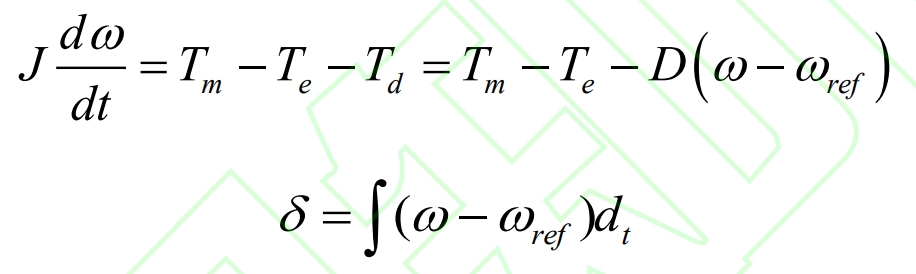
In the formula: J is the rotor inertia; ω Rated rotor synchronous angular velocity, ref, ω= 2 π f; Tm, Te, and Td represent mechanical, electromagnetic, and damping torques, respectively; D is the damping coefficient; δ For the virtual synchronous generator power angle.
According to the equation on the left side of the formula, the smaller the value of virtual inertia, the faster the change in virtual rotor angular velocity, which is not conducive to the frequency stability of the system; On the contrary, the larger the value of virtual inertia, the slower the dynamic recovery speed under system disturbance, which is more likely to cause system instability. The power angle curve and angular frequency variation curve of the synchronous generator are shown in Figure 1.
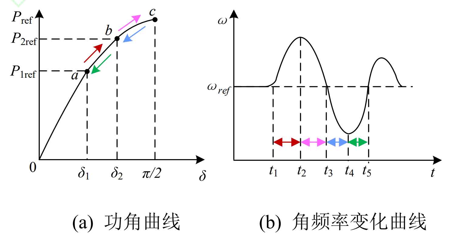
Visible, when δ∈ [0, π/2], the power of the inverter will vary with different power angles. For example, when the active power reference value of the inverter increases from P1ref in Figure 1 (a) to P2ref, the system will oscillate from the stable operating point a through attenuation and eventually stabilize at b. To describe the dynamic process of rotor angular velocity variation, Figure 1 (b) shows the variation law of rotor angular velocity over time during oscillation. As shown in the figure, the situation of rotor angular velocity and its rate of change are not the same at different time periods. Therefore, different rotor inertia can be used to promote the recovery of rotor speed. The situation of inertia demand for speed recovery is shown in Table 1.
| Time period | Change rate of rotor angular velocity | Rotor angular velocity | The demand for inertia in speed recovery |
| t ∈[t1,t2] | Forward | ω>ωref | increase |
| t ∈[t2,t3] | Negative | ω>ωref | reduce |
| t ∈[t3,t4] | Negative | ω<ωref | increase |
| t ∈[t4,t5] | Forward | ω<ωref | reduce |
According to Table 1, adopting different virtual inertia based on the different rotor angular velocity and rotor angular frequency change rate will be beneficial for reducing frequency deviation. Therefore, this article proposes a variable rotor inertia control strategy, which is based on the rate of change of rotor angular velocity d ω/ DT and its angular frequency deviation ω – ω The product of ref is used to adjust the size of the rotor inertia, thereby promoting the recovery of the speed. The variable rotor inertia can be written as:
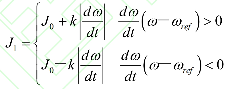
In the formula, k is a normal number, and J0 represents the steady-state inertia time constant.
In the time range [t1, t2]/[t3, t4], if the rotor angular velocity is greater than/less than the grid angular velocity, the rate of change of the rotor angular velocity is positive/negative. At this time, increasing the rotor inertia in the formula can suppress the increase of the rotor angular velocity; In the time interval [t2, t3]/[t4, t5], if the rotor angular velocity is greater than/less than the grid angular velocity, the rate of change of the rotor angular velocity is negative/positive. At this time, the second equation in the formula promotes the recovery of the rotor angular velocity by reducing the rotor inertia. Due to the linear relationship between angular frequency and frequency, when the frequency changes, the angular frequency also exhibits a similar dynamic trend.
2.2 Output Feedback Model Predictive Control
Sag control is the feedback of system frequency deviation to the output power of the unit. When the angular frequency of the system decreases, the droop coefficient is used to increase the output power of the unit, increase the rotor speed, and slow down the frequency deviation of the system; On the contrary, when the frequency of the system increases, the output power of the unit is reduced, and the rotor speed and system frequency are reduced.
In order to further reduce the significant frequency deviation generated by droop control in frequency modulation. This article combines droop control and virtual synchronous machine control to propose an output feedback model predictive control strategy for GSC.
The incremental motion equation and droop control equation of the rotor of a virtual synchronous machine can be written as:
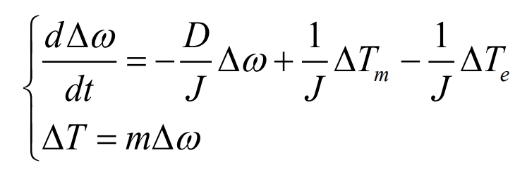
In the formula: Δ T represents the output feedback torque increment Δ T= Δ P/ ω Ref; Δ Te is the increment of disturbance electromagnetic torque; Δ Tm is the input mechanical torque increment; Δω Increment of rotor angular frequency; M is the torque droop coefficient.
The incremental equation of the formula can be written as:
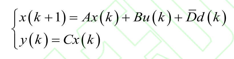
In the formula, x (k+1) represents the predicted state value for the next time step, and x (k), u (k), d (k), and y (k) represent the current state increment, respectively Δω、 Input Increment Δ Tm, disturbance increment Δ Te and output increment Δ T; A. B, D, and C represent – D/J, 1/J, -1/J, and m, respectively.
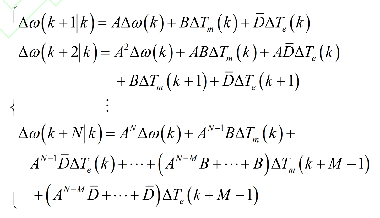
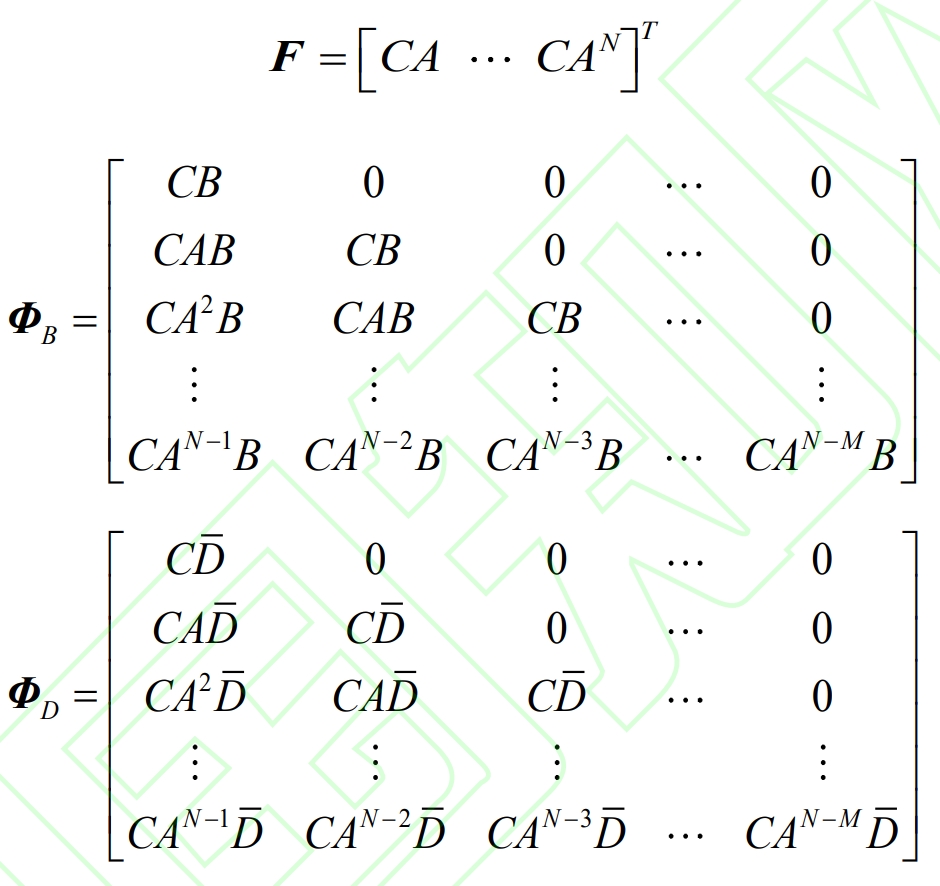
If N and M are defined as the prediction interval and control interval, respectively, and N ≥ M, the N predicted state variables at time k can be written as:
The cost function of model predictive control can be written as:

In the formula: C represents the cost function; Yref represents a known torque reference vector; Y represents the vector of actual torque values; The control matrices Q and R are diagonal matrices composed of error weight coefficients and state weight coefficients, respectively; Δ U is the increment of the input vector.
To minimize the cost function, the optimal input vector increment expression can be obtained by taking the derivative of the above equation:
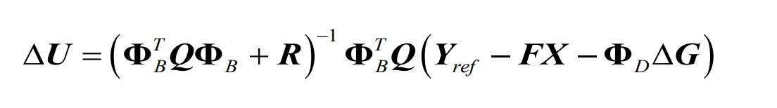
In the formula: F is the coefficient vector within the prediction interval; X is the state vector; Δ G represents adjacent moments Δ The difference in Te; Among them, parameter F Φ B Φ D satisfies:
According to the principle of rolling optimization, take Δ The first item of U serves as the control input:
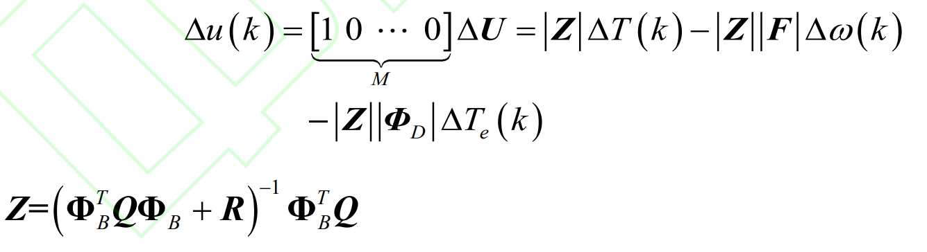
Substitute the formula into the model to predict the feedback compensation amount:
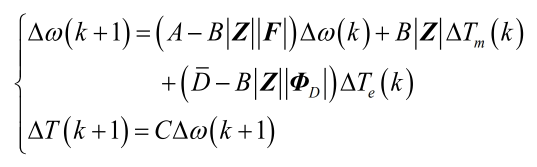
According to the formula, feedback control considers the inertia and damping coefficient of VSG, eliminates the series droop link of traditional control strategies, and adds a feedback loop for model predictive control. When frequency changes occur in the power grid, rolling optimization will adjust the feedback torque based on future moments to minimize the objective function. This strategy achieves system frequency regulation by compensating for the active power difference of the power grid to the greatest extent possible, which is beneficial for reducing the maximum frequency deviation of the system.
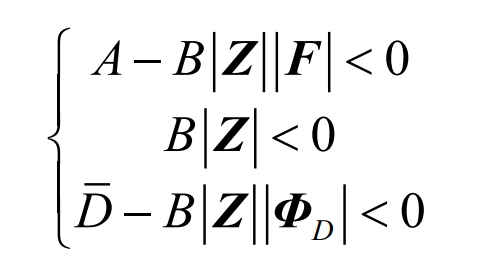
Considering the convergence conditions of feedback control, equation (12) needs to satisfy the following constraint conditions:
3. Execution process of primary frequency control
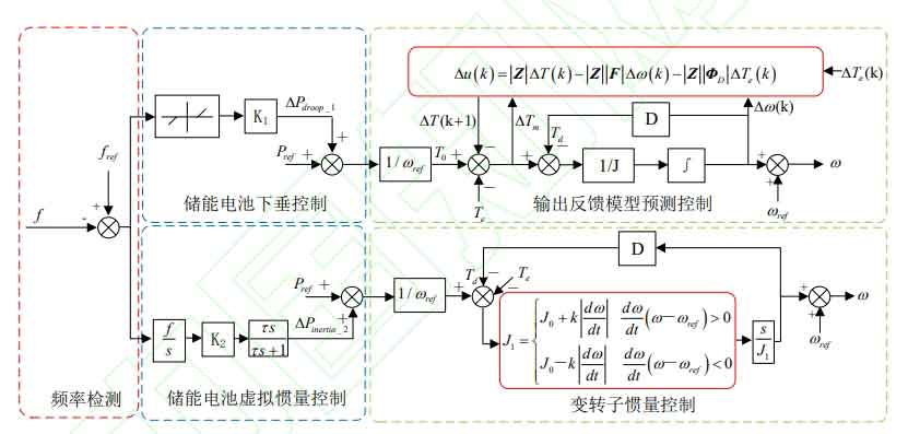
The control strategy in this article consists of an additional active power module, variable rotor inertia control, and output feedback model predictive control. The execution process is as follows:
(1) The difference between the actual value of the system frequency and the rated value is adjusted through the inertia control of the energy storage battery, and the additional inertia active power output is used as the correction for the active reference value of the variable rotor inertia control. This method aims to utilize the inertia response capability of energy storage batteries to system frequency regulation.
(2) When the measured frequency of the power grid is compared with the rated value, when the frequency deviation exceeds the allowable value of 0.003Hz, the droop control strategy of the energy storage battery is activated, and the additional droop power obtained is used as the correction for the active reference value of the output feedback model predictive control. This strategy aims to utilize the primary frequency regulation capability of energy storage batteries on the power grid.
(3) The reference active power of GSC’s variable rotor inertia control is superimposed with the additional inertia power of the energy storage battery, and the obtained result is transmitted to GSC’s variable rotor inertia control. This scheme aims to achieve real-time online adjustment of the rotor inertia of VSG with system frequency, and achieve seamless matching between the inverter inertia response and system requirements.
(4) The output feedback model predictive control of GSC transfers the combined power of the reference active power and the additional droop power of energy storage to the output feedback model predictive control of GSC. This predictive control strategy reduces the maximum frequency deviation of the power grid by constructing a feedback channel between the rotor angular frequency increment and torque increment.
In this article, two independent series control loops, namely droop control and output feedback model predictive control for energy storage batteries, virtual inertia control for energy storage batteries, and variable rotor inertia control, are synchronously executed in the control strategy. Two control loops have different rotor inertia J and J1, and the same damping coefficient D. Variable rotor inertia control aims to reduce the maximum frequency deviation of the power grid, while output feedback model predictive control is used to suppress the rate of frequency change in the power grid. VSG adjusts the output active power by controlling the input mechanical power. When the system frequency begins to decrease, the reference active power of GSC’s variable rotor inertia control and the additional inertia power of energy storage are superimposed, and the reference active power of GSC’s output feedback model predictive control and the additional droop power of energy storage are superimposed. The superimposed power restores the grid frequency by increasing the total input active power of the VSG. The variable rotor inertia control of GSC suppresses further decrease in grid frequency in the early stage due to the increase of rotor inertia; The output feedback model predictive control of GSC constructs a feedback channel between the rotor angular frequency increment and torque increment, and the rolling optimization strategy will gradually reduce the active power difference of the power grid by adjusting the feedback torque in real time at several moments to avoid high maximum frequency deviation during the frequency regulation process. The control strategy of this article is shown in Figure 2.
4. System simulation and verification
4.1 Simulation Model
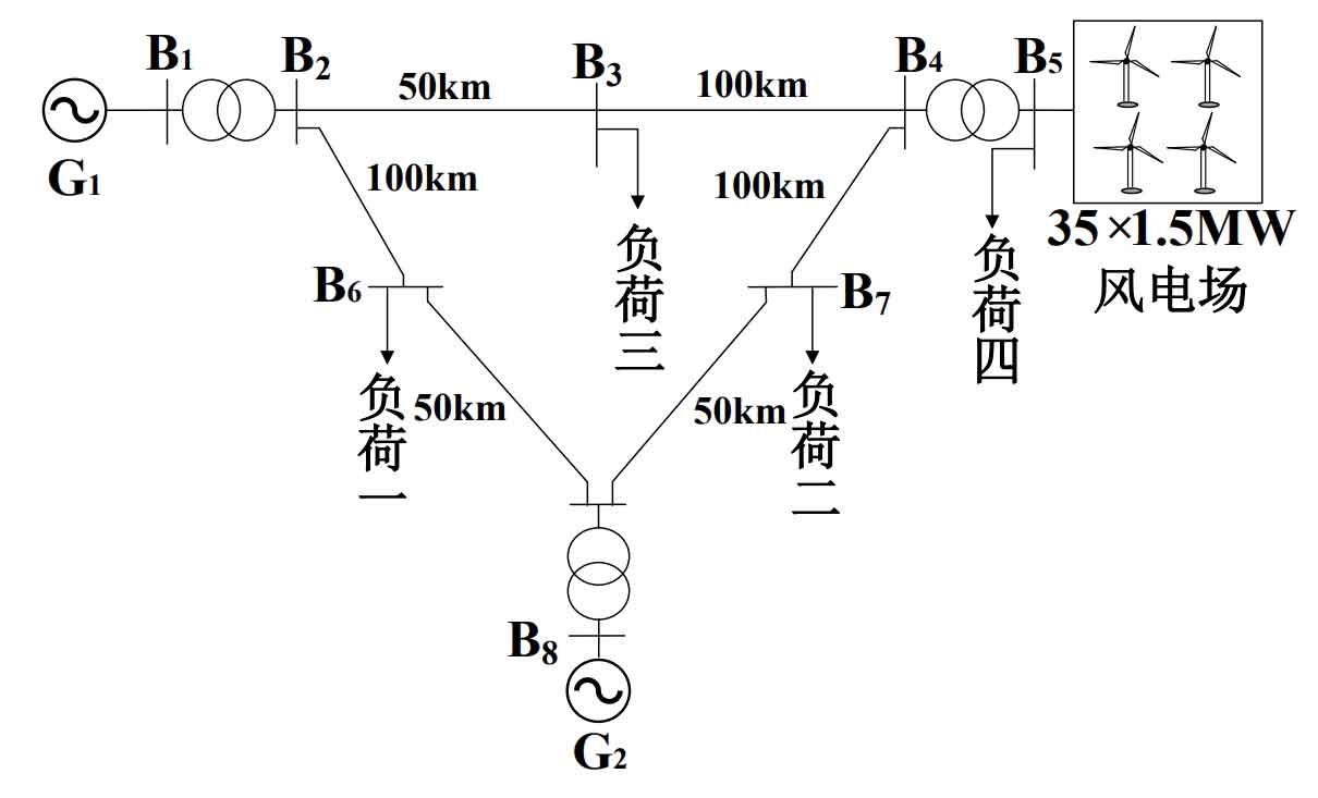
This article establishes a control strategy model for wind storage frequency regulation in Matlab/Simulink and integrates the model into a regional power grid. The overall topology is detailed in Figure 3.
| Unit number | Xd | X’d | X”d | Xq | X’q | X”q | X1 |
| G1 | 0.896 | 0.120 | 0.089 | 0.865 | 0.864 | 0.089 | 0.052 |
| G2 | 0.146 | 0.061 | 0.040 | 0.097 | 0.097 | 0.060 | 0.034 |
In the figure, G1 and G2 respectively represent synchronous generators with capacities of 100MV · A, and the rated parameters are shown in Table 2; G3 is a wind farm consisting of 35 1.5MW DFIGs, with a rated wind speed of 10m/s for the wind turbines. The rated parameters are shown in Table 3; The supporting energy storage battery has a capacity of 2.63MW, with SOC minimum, maximum, and initial values of 0.1, 0.9, and 0.5, respectively, for charging and discharging
| Parameters | Numerical value | Parameters | Numerical value |
| Rated voltage/V | 575 | Rotor resistance (p.u.) | 0.005 |
| Inertia constant/s | 5.04 | Rated frequency/Hz | 50 |
| Rotor inductance (p.u.) | 0.156 | DC bus capacitance/F | 0.35 |
| Stator resistance (p.u.) | 0.00706 | Excitation inductance (p.u.) | 2.9 |
| Grid side filtering inductance (p.u.) | 0.15 | Stator inductance (p.u.) | 0.171 |
| Polar logarithm | 3 | Grid side filtering resistor | 0.0015 |
Set the electrical efficiency to 0.9; The impedance of the lines used for connecting the regional power system is 0.17j0.13 Ω/km, and the length is shown in Figure 3; The active power of loads one, two, three, and four are 117MW, 35MW, 95MW, and 2.5MW, respectively.
In this control strategy, the droop coefficient K1 and virtual inertia coefficient K2 of the additional active power generation module are 30 and 0.3, respectively. The damping coefficient D, steady-state inertia time constant J0, and normal number k for variable rotor inertia control are set to 10 N • S • m ^ -1, 0.2 kg • m ^ 2, and 50, respectively; In output feedback model predictive control, the torque droop coefficients m and J are taken as -0.0018N • S • Hz ^ 1 and 1.8kg • m ^ 2, respectively, and Q and R are taken as unit diagonal matrices.
In order to verify the correctness and effectiveness of the model, this paper compares the frequency response characteristics of wind turbines without frequency regulation control, comprehensive inertial control (wind turbine virtual inertia+virtual droop control), energy storage batteries participating in frequency regulation control, and the control strategy in this paper. The frequency response characteristics of wind turbines under the scenarios of step sudden increase load, step sudden increase wind speed, random wind speed, and random load are analyzed.
4.2 Step load
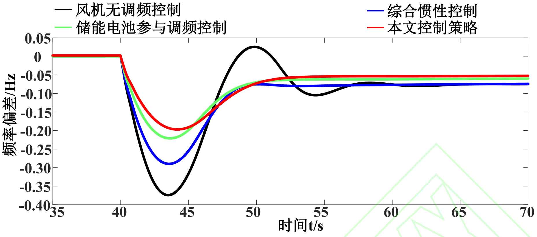
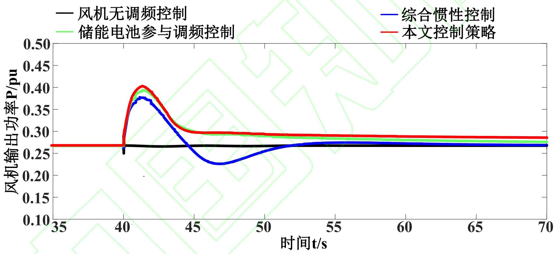
To verify the frequency of the power grid and the response characteristics of wind turbines under step load, load one was increased by 30MW at 40s. The frequency deviation of the four control strategies under step load and the waveform of the output active power of the wind turbine are shown in Figures 4 and 5. The system frequency regulation indicators are shown in Table 4.
| Control strategy | Δfmax/Hz | Δfsteady/Hz | ΔPge max(p.u.) | dfinitial/(Hz·s^-1) |
| Fan without frequency regulation control | 0.375 | 0.075 | 0.269 | 6.314 |
| Integrated inertial control | 0.288 | 0.075 | 0.373 | 5.145 |
| Energy storage participates in frequency modulation control | 0.224 | 0.063 | 0.382 | 4.011 |
| Control strategy in this article | 0.208 | 0.058 | 0.398 | 3.078 |
From Figure 4, it can be seen that after being disturbed by step loads, the frequencies corresponding to the four control strategies all sharply decrease, and after a brief dynamic process, the grid frequency reaches a stable state. In the process of dynamic frequency changes in the system, the other three control strategies avoid secondary frequency drops and system frequency oscillations compared to wind turbine non frequency modulation control.
From Figure 5, it can be seen that the frequency degradation of wind turbines without frequency modulation control is the most severe. This is because when the system frequency decreases, the wind turbine cannot respond to the system power demand, and the output power of the unit is not affected by changes in the system frequency. The participation of energy storage batteries in frequency modulation control mainly utilizes the output power of energy storage batteries to assist in restoring system frequency, but the frequency modulation effect is limited. This control strategy not only utilizes energy storage batteries to provide output power for frequency regulation, but also utilizes the primary frequency regulation capability of the inverter controlled by a virtual synchronous generator. Therefore, the frequency regulation effect is best under step load.
According to Table 4, the control strategy proposed in this paper reduces the maximum frequency deviation and steady-state frequency deviation. Compared with the participation of energy storage batteries in frequency modulation control, the maximum frequency deviation and steady-state frequency deviation of this control strategy are reduced by 7.14% and 7.94%, respectively. The control strategy and integrated inertial control in this article have reduced the maximum frequency deviation by 27.78% and the steady-state frequency deviation by 22.67%. In addition, the maximum output active power of wind turbines generated by the control strategy in this article has increased by 6.7%, 4.19%, and 47.96% compared to integrated inertial control, energy storage battery participation in frequency regulation control, and wind turbine non frequency regulation control, respectively. The initial frequency drop speed of the control strategy in this article decreased by 40.17%, 23.26%, and 51.25% compared to the other three, respectively.
4.3 Stepwise wind speed
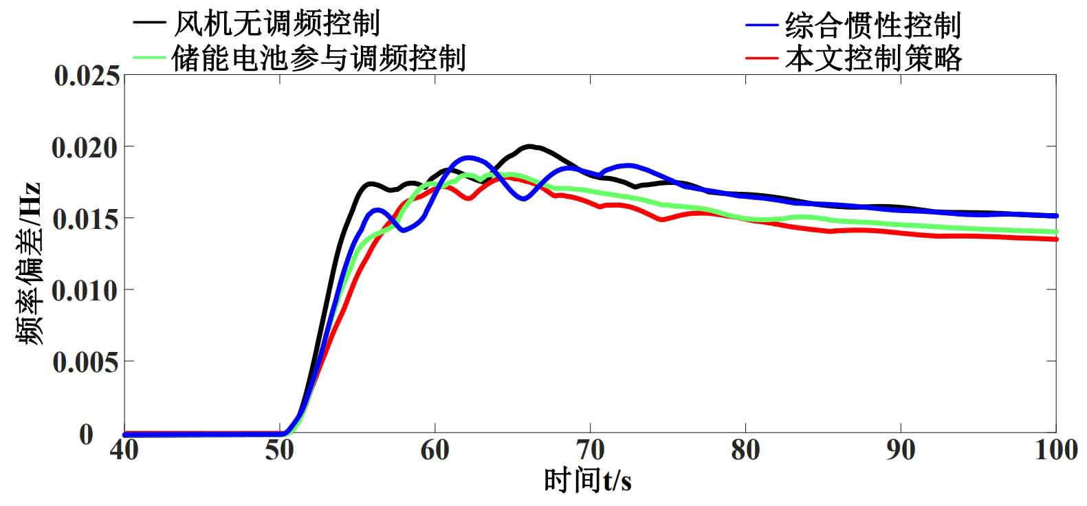
To verify the frequency of the system and the response characteristics of the wind turbine at step wind speed, a step wind speed of 0.02 p.u. was added at 50 seconds. The frequency changes and active power changes of the wind turbine under four strategies are shown in Figures 6 and 7. The system frequency evaluation indicators are shown in Table 5.
| Control strategy | ΔFmax/Hz | ΔFsteady/Hz | ΔPge max (p.u.) |
| Fan without frequency regulation control | 0.0204 | 0.015 | 0.519 |
| Integrated inertial control | 0.0191 | 0.015 | 0.519 |
| Energy storage batteries participate in frequency modulation control | 0.0178 | 0.0138 | 0.539 |
| Control strategy in this article | 0.0176 | 0.0133 | 0.544 |
As shown in Figure 6, when the step wind speed is added in the initial stage, the frequency deviation corresponding to the four control methods increases rapidly. The frequency deviation of the wind turbine without frequency modulation control and comprehensive inertial control is significantly higher than the other two control methods. The frequency modulation effect of the control strategy in this article is slightly better than that of a simple energy storage battery participating in frequency modulation control.
As shown in Figure 7, when the system frequency reaches a stable state, the output power of the wind turbine no longer changes. The output power is ranked in descending order as follows: control strategy in this article, energy storage battery participation in frequency regulation control, comprehensive inertial control/wind turbine non frequency regulation control. This result indicates that the control strategy proposed in this paper can not only make reasonable use of the output power of energy storage batteries for frequency regulation, but also fully tap into the frequency regulation performance of the inverter to improve the overall output power of wind turbines under step wind speed and reduce frequency deviation.
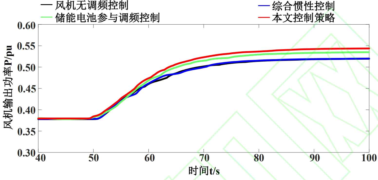
Table 5 provides quantitative indicators of the maximum frequency deviation, steady-state frequency deviation, and maximum output power of wind turbines for each control strategy during the period of 50-100 seconds. As shown in the table, when there is a step wind speed disturbance in the system, the grid frequency caused by each control strategy is above 50Hz. The maximum frequency deviation of non frequency modulation control and integrated inertial control is not significantly different, only 0.0013Hz, while the steady-state frequency deviation and maximum output power of wind turbines are the same, respectively, at 0.015Hz and 0.159 p.u. The frequency drop is the most severe and the frequency modulation effect is the worst for non frequency modulation control and integrated inertial control. The participation of energy storage batteries in frequency regulation control results in relatively small frequency deviation due to the obstruction of frequency drop caused by the output of energy storage batteries, with a maximum frequency deviation of 0.0178Hz and a steady-state frequency deviation of 0.0138Hz; The maximum frequency deviation, steady-state frequency deviation, and maximum output power of wind turbines in this control strategy are 0.0176Hz, 0.0133Hz, and 0.544 p.u., respectively, indicating the best frequency regulation capability.
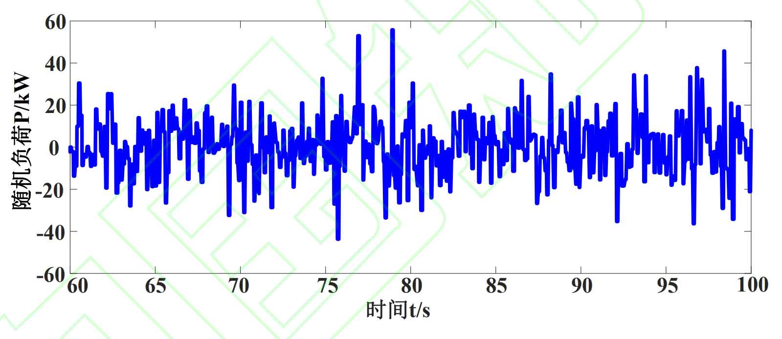
4.4 Random load disturbance
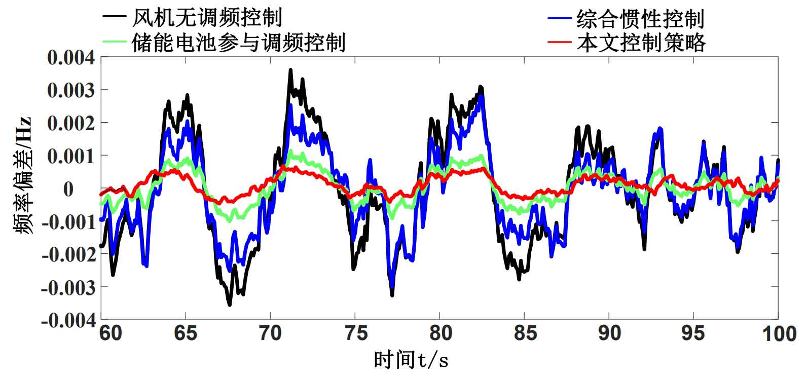
Add a 40 second random load disturbance at load one, and the load disturbance situation is shown in Figure 8. The frequency deviation and the output power waveform of the wind turbine are shown in Figures 9 and 10, respectively. The evaluation indicators for the four control strategies are shown in Table 6.
| Control strategy | ΔFpv max/Hz | ΔFmax/Hz | ΔPpv max (p.u.) | ΔPge max (p.u.) |
| Fan without frequency regulation control | 0.0071 | 0.0036 | 0.0044 | 0.2702 |
| Integrated inertial control | 0.0061 | 0.0034 | 0.0061 | 0.2703 |
| Energy storage batteries participate in frequency modulation control | 0.0021 | 0.0011 | 0.0108 | 0.2728 |
| Control strategy in this article | 0.0011 | 0.0006 | 0.0122 | 0.2736 |
From Figure 9, it can be seen that under random loads, the frequency deviation corresponding to wind turbine control without frequency modulation and integrated inertial control is relatively close. Among them, the frequency degradation of the power grid is most severe when there is no frequency modulation. The participation of energy storage batteries in frequency modulation control has a good inhibitory effect on system frequency deviation, which is significantly better than the first two. The frequency deviation suppression effect of the control strategy in this article is the best under random load disturbances.
From Figure 10, it can be seen that the output power of wind turbines is ranked in descending order as follows: control strategy in this paper, participation of energy storage batteries in frequency regulation control, comprehensive inertial control, and wind turbine non frequency regulation control. This result indicates that relying on the frequency regulation ability of both energy storage batteries and inverters simultaneously has the best effect on reducing system frequency deviation.
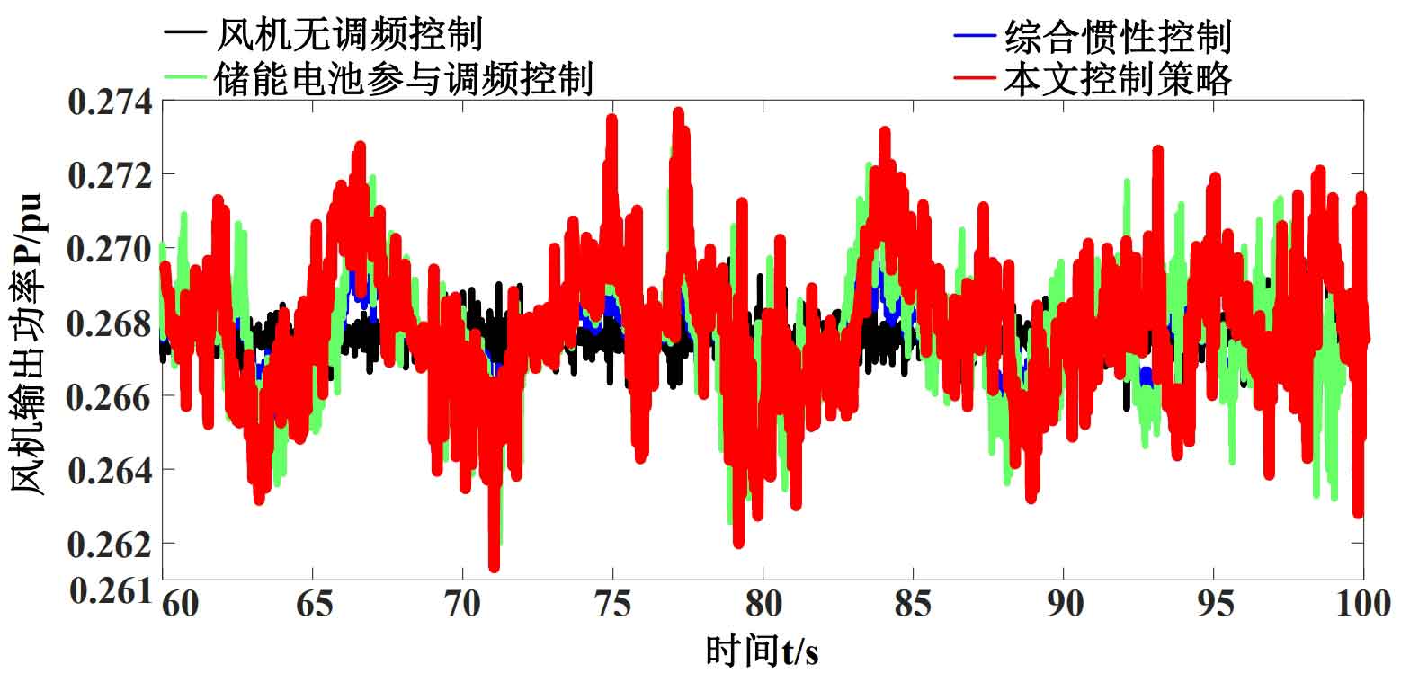
According to Table 6, the maximum peak valley difference and maximum frequency deviation of the wind turbine without energy storage are higher than those with energy storage, while the maximum output power peak valley difference and maximum output power of the wind turbine without energy storage decrease compared to those with energy storage. The control strategy in this article reduces the maximum peak valley difference and maximum frequency deviation of frequency regulation control by 0.001 Hz and 0.0005 Hz respectively compared to energy storage batteries, while the maximum output power peak valley difference and maximum output power of wind power increase by 0.0014 p.u. and 0.0008 p.u., respectively; This result indicates that the control strategy proposed in this paper can effectively utilize the frequency modulation capability of the inverter.
5. Conclusion
Improving inertia response and primary frequency regulation performance are two key requirements for power grid frequency regulation. Considering that the use of VSG control in GSC can compensate for the shortcomings of energy storage participating in grid frequency regulation, this paper proposes an energy storage battery that takes into account the dynamic inertia response characteristics to participate in grid primary frequency regulation control. Among them, using the active power generated by energy storage batteries through virtual inertia control as additional power for variable rotor inertia control can utilize the inertia support ability of energy storage on the power grid, while using the active power generated by energy storage batteries through droop control as additional power for output feedback model predictive control can utilize the primary frequency regulation performance of energy storage on the power grid. The variable rotor inertia control strategy of VSG improves the inertia response capability of the system by adjusting the rotor inertia in real-time with the system frequency. The output feedback model predictive control strategy utilizes the feedback channel between rotor angular frequency increment and torque increment to predict and compensate for system frequency deviation, significantly reducing the maximum frequency deviation of the power grid.
In summary, this control strategy solves the problem of insufficient system inertia response and primary frequency regulation capability when using a single wind power frequency regulation or wind storage frequency regulation, effectively reducing grid frequency deviation and frequency change rate. When the energy storage capacity is limited, the effect of improving the frequency stability of the power grid is better.