
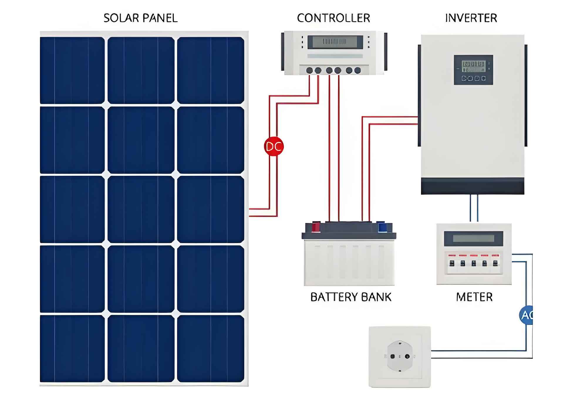
With the global push toward carbon neutrality, solar inverters have become critical components in renewable energy systems. This article focuses on the electrical insulation design of 1,100 V DC/380 V AC string solar inverters, addressing key challenges in safety, cost efficiency, and regulatory compliance.
Insulation Classification in Solar Inverters
String solar inverters integrate multiple insulation types to ensure operational safety:
- Functional Insulation: Required between DC+ and DC- terminals (①) and AC phase conductors (③).
- Basic Insulation: Applied between live parts and grounded enclosures (④, ⑤).
- Reinforced/Double Insulation: Mandatory between communication interfaces and power circuits (⑦).
Electrical Clearance Design
The minimum clearance for basic insulation is determined by:
$$D_{air} = K_{air} \cdot \max(D_{air1}, D_{air2}, D_{air3})$$
Where:
- $D_{air1}$: Clearance from maximum working voltage
- $D_{air2}$: Clearance from transient overvoltage
- $D_{air3}$: Clearance from temporary overvoltage
- $K_{air}$: Altitude correction factor
| Voltage Type | Max Working Voltage | Transient Overvoltage | Temporary Overvoltage | Minimum Clearance |
|---|---|---|---|---|
| DC 1,100 V | 1,100 V | 4,800 V | N/A | 4.3 mm |
| AC 380 V | 312 V (peak) | 4,000 V | 2,120 V (peak) | 3.0 mm |
Creepage Distance Calculation
Creepage distances for printed circuit boards (PCBs) are calculated using:
$$D_{creep} = \frac{V_{rms}}{CTI} \cdot M$$
Where:
- $CTI$: Comparative Tracking Index (Material property)
- $M$: Pollution degree multiplier (1.0 for pollution level 2)
| Circuit Type | Working Voltage | Pollution Level | CTI Group | Creepage Distance |
|---|---|---|---|---|
| DC Input | 1,100 V | 2 | IIIa (CTI ≥ 175) | 5.52 mm |
| AC Output | 380 V | 2 | II (CTI ≥ 400) | 1.90 mm |
Insulation Testing Protocols
Solar inverters must pass three critical tests:
- AC Withstand: 2Un + 1,000 V (1 min)
- DC Withstand: 1.414 × AC test voltage (1 min)
- Impulse Voltage: 1.2/50 μs waveform (5 positive + 5 negative pulses)
Cost Optimization Strategies
- Use reinforced insulation only at communication interfaces (⑦)
- Implement multi-layer PCBs to reduce inner-layer pollution levels
- Select CTI Group II materials for AC circuits
This insulation design methodology enables string solar inverters to achieve 30% cost reduction while maintaining full compliance with NB/T 32004 and IEC 62109 standards. Field tests demonstrate less than 0.1% failure rate in 1,000+ installations across 2,000–4,000 m altitudes.