
1. Multiple main circuit topologies of solar inverters
With the booming development of the photovoltaic power generation industry, the research level of solar inverters is also constantly improving. At present, a large number of different types of solar inverters have emerged, including two-level, three-level, and multi level solar inverters. Two level solar inverters are a type of early developed solar inverter that is more suitable for low power and low switching frequency, and are widely used in distributed power generation equipment. But with the rise of centralized photovoltaic power generation industry, high-power and high switching frequency solar inverters are constantly being developed, and at the same time, the practicality of three-level solar inverters is widely recognized.
1.1 Topology structure of two-level solar inverters
The two-level three-phase solar inverter is a type of solar inverter that was widely installed during the early development period of photovoltaics. It has the characteristics of simple structure, few switching devices, and low cost, and has great potential in low-power situations. Its topology structure is often divided into half bridge, full bridge, and other structures. The three-phase half bridge type is more suitable for three-phase power grid balance systems, as shown in Figure 1; However, three-phase full bridge type is rarely used due to the use of more power switching tubes and higher costs.
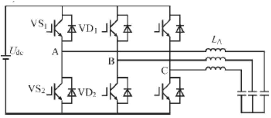
From Figure 1, it can be seen that the two-level three-phase solar inverter has three bridge arms, with two power switching tubes on each upper and lower part of each bridge arm. For example, the switching tubes on the upper and lower bridge arms of phase A are VS1 and VS2. Two switching tubes on the same bridge arm cannot conduct simultaneously, and three switching tubes can conduct simultaneously at any time. When VS1 conducts and VS2 disconnects, node A is connected to the positive end of the DC power supply, and the output voltage is Van=Vd/2; When VS1 disconnects and VS2 conducts, node A is connected to the negative terminal of the DC power supply, and the output voltage is Van=- Vd/2. Similarly, B and C also determine their potential based on the switching status of the upper and lower switching tubes. According to this conduction principle, there are two levels of output phase voltage for each phase, which constitutes the working principle of a two-level three-phase solar inverter.
1.2 Topology structure of E-type three-level solar inverter
The E-type three-level solar inverter, also known as the diode clamped three-level solar inverter, has two additional voltage divider capacitors C1 and C2, as well as the addition of switching tubes and clamping diodes compared to two-level solar inverters in terms of structure. In terms of output voltage, the two-level output voltage is ± Vd/2, while the three-level output voltage has three modes: 0, Vd/2, and – Vd/2. The E-type three-level solar inverter, as a solar inverter developed in recent years, not only meets the needs of higher power generation systems, but also reduces the size of filtering inductance and other losses. Its topological structure is shown in Figure 2 (a).
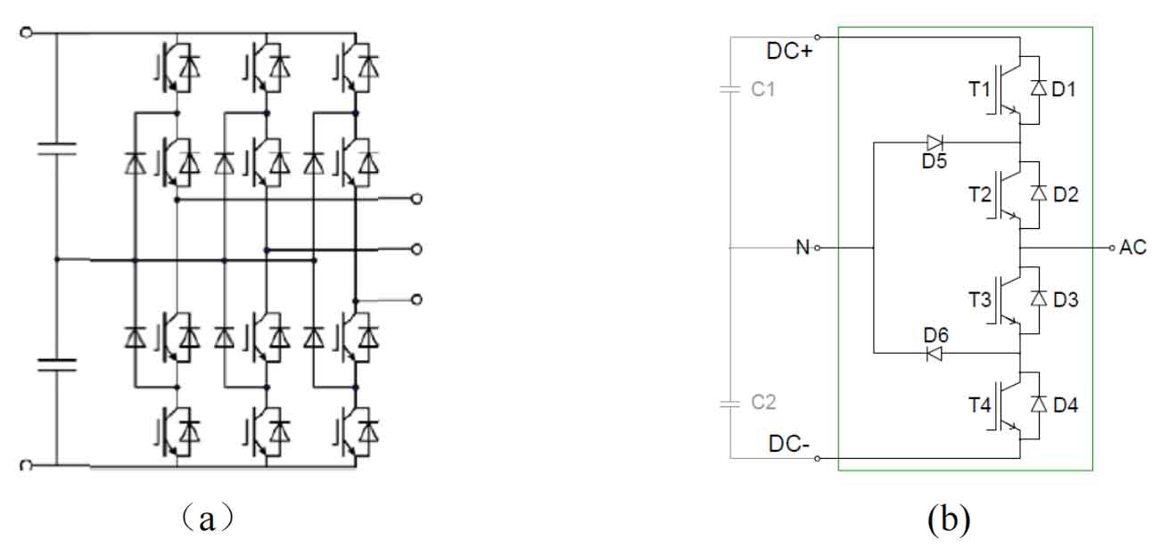
As shown in Figure 2 (a), the diode clamped three-level solar inverter adopts a circuit with neutral point clamping consisting of 12 power switching tubes and 6 clamping diodes. Taking phase A as an example, as shown in Figure 2 (b), when T1 and T2 conduct and T3 and T4 turn off, the output voltage at this time is Vd/2; When T2 and T3 are conducting and T1 and T4 are turned off, the output voltage is 0; When T3 and T4 conduct and T1 and T2 turn off, the output voltage is – Vd/2, and the other two phases are similar. This topology structure increases the number of components, but due to the fact that the/du dt generated by switching action is theoretically only half of the traditional two-level, it reduces the voltage resistance requirements of the power switching transistor and also increases the third voltage value (0 voltage value), resulting in better quality of the output waveform.
1.3 Topology structure of T-type three-level solar inverter
The T-type three-level solar inverter is a half bridge three-level structure developed by Conergy Company. It not only retains the three output voltage modes of three-level, but also has the advantages of fewer switching devices, lower conduction loss, more uniform power loss, fewer independent driving power sources, and less strict shutdown timing requirements compared to traditional E-type three-level solar inverters, Therefore, it has become the development direction of high-power photovoltaic power generation in the future. Its topological structure is shown in Figure 3.
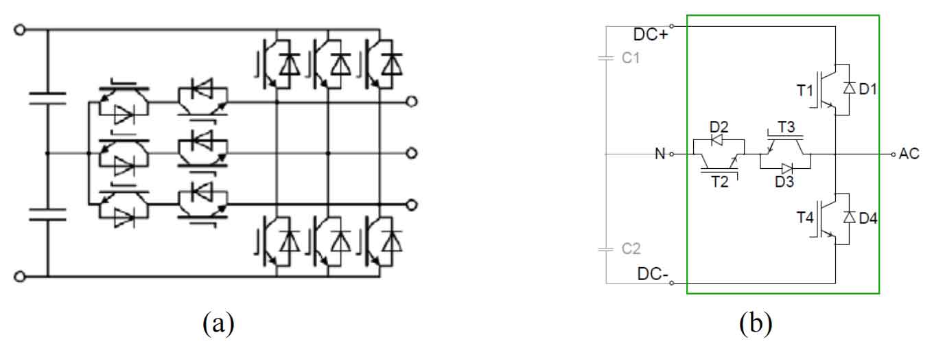
The T-type three-level solar inverter uses a total of 12 switching tubes, with a total of 4 switching tubes per phase bridge arm. Taking phase A as an example, as shown in Figure 3 (b), T1 and T4 are the upper and lower main switch tubes, and T2 and T3 are the intermediate tubes. When T1 and T2 are conducting and T4 and T3 are turned off, the output voltage is Vd/2 at this time; When T2 and T3 are conducting and T1 and T4 are turned off, the output voltage is 0; When T4 and T3 conduct and T1 and T2 turn off, the output voltage at this time is – Vd/2.
2. Loss Analysis of Different Topological Structures
The primary consideration for improving the efficiency of solar inverters is the energy loss issue that exists. By selecting the solar inverter with the lowest energy loss, the output power of the solar inverter can be effectively improved, thereby achieving the goal of improving efficiency. The losses of solar inverters are often divided into on state losses and switching losses. Due to different topology structures, the number of components and working methods, there is also a significant difference in energy losses.
2.1 Loss analysis of two-level solar inverters
Due to its simple structure, long development time, and relatively more mature technology, there is relatively more research on the losses of two-level solar inverters. Its power loss is divided into on state loss Pcond, switching loss Psw, and filtering loss inductance loss PL.
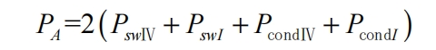
Taking phase A as an example, the relationship between the driving signals S1 and S2 and the output voltages V and I is similar to the T-type three-level shown in Figure 5. The action of the switch can divide a voltage cycle into I-IV regions based on the direction of V and I. Due to the dual relationship between regions IV and I, as well as regions II and III, the total power loss of phase A is:
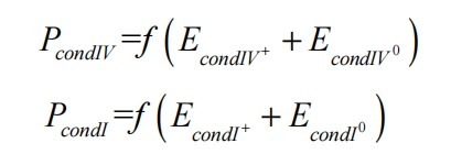
As shown in the figure, in region IV, the current direction is negative. At this time, the current flows into the solar inverter, and VD1 and VS2 alternate conduction. Ignoring the change of current in one switching cycle, the on state loss is:
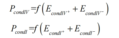
In the formula, EcondIV+represents the on state loss of the A-phase output positive voltage in the IV region; EcondIV − is the on state loss of the negative output level of phase A; EcondI+and EcondI − are the on state losses when outputting the positive and negative levels of phase A in the I region; F is the frequency of the output voltage.
The expression for the on state loss is:
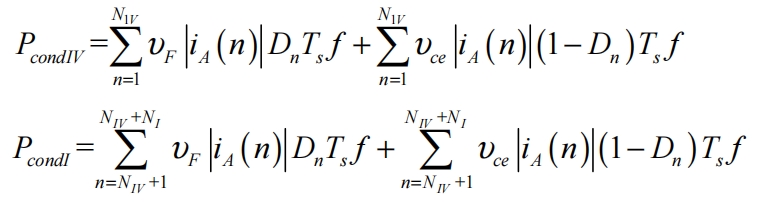
In the formula, υ F and υ CE represents the conduction voltage drop of the reverse parallel diode and the conduction voltage drop of the IGBT, respectively; Dn is the duty cycle of the nth switch; Ts is the switching cycle; IA (n) is the current value flowing through the device during the nth switching of phase A; NIV and NI represent the number of switches corresponding to the two regions.
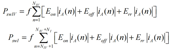
The switching loss of power switching tubes is defined as Eon for IGBT turn-on loss, Eoff for turn-off loss, and Err for diode reverse recovery loss when calculating the switching loss due to the overlapping area generated by voltage and current changes in the operation engineering of IGBT and reverse diode. The switching loss can be expressed as:
Due to the three-phase nature of solar inverters, the total power loss is three times that of single-phase inverters, resulting in P=3 × PA.
2.2 Analysis of losses in E-type three-level solar inverters
Compared to traditional two-level solar inverters, E-type three-level solar inverters have different numbers and types of power loss devices due to the addition of zero level potential. However, they can also be divided into on state loss and switching loss.
The switching process of the IV and I regions is shown in Figure 4.
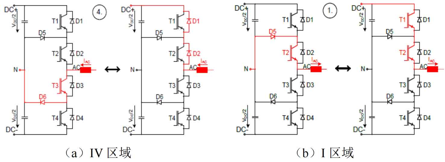
Taking phase A as an example, the relationship between the driving signals S1~S4 and the output voltages V and I is also similar to the T-type three-level shown in the figure. As shown in Figure 4 (a), when D1 and D2 are conducting, the current is negative and flows towards the solar inverter, displaying a high level; When T3 and D6 are conducting, the current is negative and flows to the solar inverter, displaying as zero level. At this point, it corresponds to the conduction process of the switch in region IV. As shown in Figure 4 (b), when T1 and T2 are conducting, the current is positive and flows out of the solar inverter, displaying as high level; When T2 and D5 are conducting, the current is positive and flows out of the solar inverter, displaying as zero level. At this point, it corresponds to the conduction process of the switch in region I. The power loss expression is the same as the two-level expression formula, and the on state loss calculation formula only needs to modify the negative level in the formula to zero level, that is:
The on state loss is:
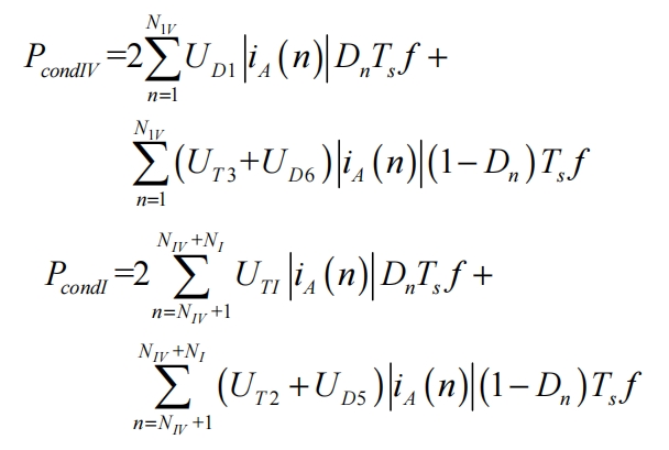
In the formula, UD1, UTI, UT 2, UT 3, UD5, and UD6 correspond to the conduction voltage drop of each switch tube (as UD1=UD2 and UT1=UT2, they are directly expressed in multiples in the expression).
Due to the fact that the power switching tubes of the E-type three-level and two-level solar inverters are the same, the expression for switching losses is the same as that of the two-level expression. Therefore, we will not elaborate on this further. Similarly, the total loss power of the three phases is equal to the sum of the three phases, which is P=3 × PA.
2.3 Analysis of losses in T-type three-level solar inverters
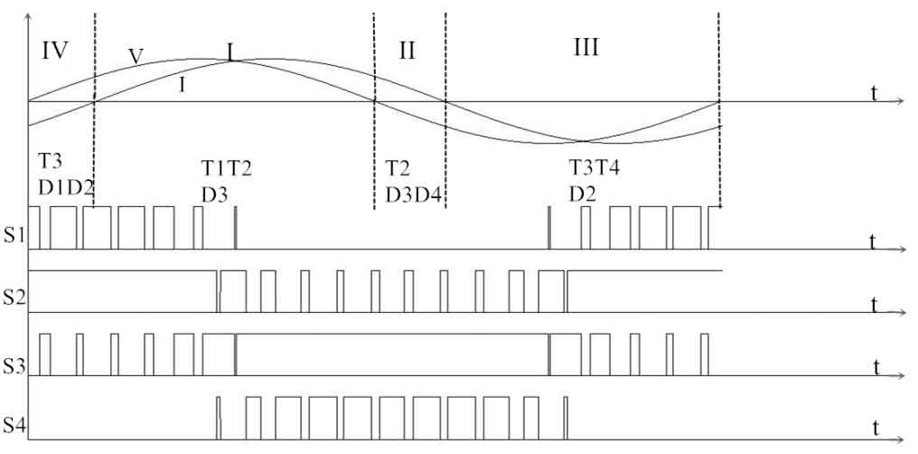
The structure of the T-type three-level solar inverter is similar to that of the E-type solar inverter, but with fewer components. Its power loss can also be divided into two parts: on state loss and switching loss. The relationship between the driving signals S1~S4 and the output voltages V and I is shown in Figure 5.
The switching process of the IV and I regions is shown in Figure 6.
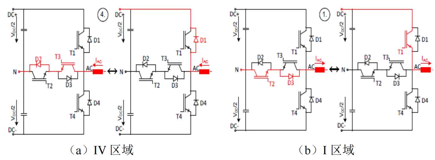
Taking phase A as an example, as shown in Figure 6 (a), when D2 and T3 are conductive, the current is negative and flows towards the solar inverter, indicating zero potential; When D1 is conducting, the current is negative and flows to the solar inverter, indicating a high level. At this point, it corresponds to the switching process in region IV of the output voltage and output current diagram U-1. From Figure 6 (b), it can be seen that when T2 and D3 are conductive, the current is positive and flows towards the load end, showing zero potential; When T1 is conducting, the current is positive and flows towards the load end, indicating a high level. The switching process corresponding to the I region in the U-I diagram. Due to the fact that both T-type and E-type solar inverters are three-level solar inverters, the calculation method for power loss is similar. The total power loss is equal to the sum of three-phase losses and the three-phase is symmetrical, that is, P=3 × PA. If the PA expression is the same as the formula and the on state loss Pcond is the same as the formula, then the on state loss is calculated as:
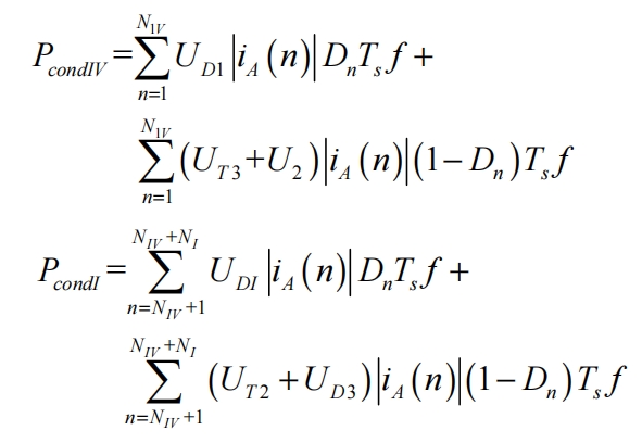
The various meanings in the formula are the same as in the previous text.
The T-type solar inverter is similar to the E-type solar inverter, where each power switch corresponds to a switch and a reverse diode. In terms of switching losses, they have the same properties. Therefore, the calculation of switching losses for the T-type solar inverter is the same as the formula, and we will not elaborate further here.
2.4 Comparison and Analysis of Efficiency of Three Solar Inverters
The three types of solar inverters have different device losses due to their different structures, switch sequences, and device quantities. Therefore, in order to achieve optimal efficiency of the entire photovoltaic system, it is necessary to choose solar inverters with lower losses, lower radiator requirements, and better filter volume. This chapter mainly conducts semi physical simulation and experimental research on the two-level, E-type three-level, and T-type three-level solar inverters calculated in the previous text, selecting the most suitable solar inverter to achieve higher efficiency.
As mentioned earlier, the power devices of the three types of solar inverters generate components with losses during half a sine voltage cycle.
The switching losses of the three types of solar inverters are the same, all of which are losses caused by IGBT’s primary conduction, turn off, and reverse recovery. However, due to the different structures of the three types of solar inverters, they use different components in the on state losses in the IV and I regions of the voltage positive half cycle. Among them, the two-level switch participating in the action has only two IGBTs in each region; E-type three-level has four switch actions in the same area, while T-type three-level has three switch actions.
In terms of equipment cost, two-level has more advantages, while T-type three-level has a lower cost compared to E-type three-level. Along with the difference in the number of devices, it means that the three topologies also have certain differences in power loss.
Based on the calculation formula as the theoretical basis, IGBT was used as the switching device to conduct semi experimental simulation calculations on the power loss and allowable temperature of the heat sink of three solar inverters. The calculation conditions are shown in Table 1.
| Type | Model | Drive resistance (Rs/Ω) | Environmental temperature (Ta/℃) | Filter inductance (L/mH) | Switching frequency (fsw/kHz) |
| Two level | SEMix404GB12E4s | 2 | 40 | 0.30 | 5 |
| E-type three-level | SKIM401MLI07E4 | 2 | 40 | 0.05 × 2 | 5 |
| T-type three-level | SKIM401TMLI12E4B | 2 | 40 | 0.05 × 2 | 5 |
When calculating, for the purpose of comparison, the maximum power loss is calculated using a DC voltage of 800V as the maximum power point, with a voltage drop of 0.9U and a power factor of cos ψ= 0.9, there are 6 parallel devices on the same radiator. The power loss values and temperature changes of the three types of solar inverters with different structures are shown in Tables 2-4.
| Project | T1(T2) | D1(D2) | per module | 3-phase inverter |
| On state loss (Pcond/W) | 162 | 71 | 466 | 1398 |
| Switching loss (Psw/W) | 185 | 43 | 456 | 1368 |
| Total loss (Ploss/W) | 347 | 114 | 922 | 2766 |
| Junction temperature (Tj/℃) | 120 | 110 | ||
| Radiator temperature (Ts/℃) | 67.0 |
| Project | T1 (T4) | T2 (T3) | D1 (D4) | D2 (D3) | D5 (D6) | per module | 3-phase inverter |
| On state loss (Pcond/W) | 78 | 185 | 0.59 | 0.59 | 103.4 | 735.16 | 2205.48 |
| Switching loss (Psw/W) | 55 | 6 | 0.41 | 0.00 | 3.3 | 129.42 | 388.26 |
| Total loss (Ploss/W) | 134 | 191 | 1.00 | 0.59 | 106.7 | 866.58 | 2599.74 |
| Junction temperature (Tj/℃) | 105 | 120 | 72 | 72 | 109 | ||
| Radiator temperature (Ts/℃) | 72.0 | 67.0 |
| Project | T1 (T4) | T2 (T3) | D1 (D4) | D2 (D3) | per module | 3-phase inverter |
| On state loss (Pcond/W) | 99.7 | 110.1 | 0.7 | 93.4 | 607.8 | 1823.4 |
| Switching loss (Psw/W) | 71.6 | 2.6 | 0.3 | 4.0 | 157 | 471.0 |
| Total loss (Ploss/W) | 171.3 | 112.7 | 1.0 | 97.4 | 764.8 | 2294.4 |
| Junction temperature (Tj/℃) | 120.0 | 120.0 | 93.8 | 120.0 | ||
| Radiator temperature (Ts/℃) | 120.0 |
According to Tables 2-4, it can be seen that the losses between different switching devices of the three types of solar inverters are compared. As shown in Figure 7.
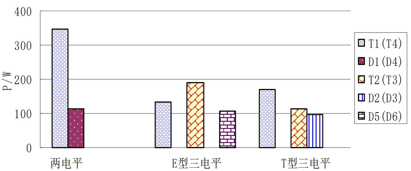
From Figure 7, it can be seen that the power loss of the reverse recovery diodes D1 (D4) and D2 (D3) on the same bridge arm of the three types of solar inverters is much smaller than that of the corresponding IGBT tubes T1 (T4) and T2 (T3). Among them, the power loss of the reverse recovery diodes in the E-type three-level and T-type three-level structures is less than 1% of the power loss of the IGBT tubes. This indicates that the energy loss of IGBT plays a major role during the operation of the switch tube, which is consistent with the power loss relationship diagram provided by the IGBT manufacturer on the Datasheet, as shown in Figure 8.
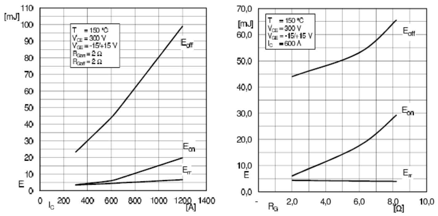
From Figure 8, it can be seen that under the same operating conditions, the power loss Eon when IGBT is turned on and the power loss Eoff when it is turned off are much greater than the power loss Err of the reverse recovery diode, which verifies the accuracy of the simulation experiment. At the same time, the diode D5 (D6) unique to E-type three-level and the IGBT transistor T2 (T3) unique to T-type three-level have relatively high power losses, especially the T-type three-level IGBT transistor T2 (T3) and its corresponding directional recovery diode D2 (D3) do not follow the general pattern of bridge arm switching tubes. This is because during the switching process of E-type and T-type in the four regions of I-IV in a single cycle, the three-level structure solar inverter will display three levels. Every time zero current is displayed, the E-type solar inverter always has a diode connected to the bus conducting, while the T-type solar inverter always has an IGBT tube connected to the bus and a reverse recovery diode conducting. As a result, the switch tube connected to the bus will frequently conduct and turn off, causing greater power loss. At the same time, if the IGBT on the busbar of the T-type solar inverter has the same switching frequency as the reverse recovery diode, the power loss is similar.
From Tables 2-4, it can be seen that the difference in power loss between the IGBT switching tubes on the same bridge arm and the reverse recovery diode does not result in a significant temperature difference between the IGBT chip junctions. This is due to the highly integrated nature of the IGBT, where each switching tube is tightly packaged together, resulting in heat conduction that affects the temperature change of the entire IGBT module. Therefore, when selecting a heat sink, the maximum junction temperature of the switching tube should be considered.
According to Tables 2-4, it can be seen that the on state loss Pcond, switch loss Psw, and total loss Ploss of the three types of solar inverters are compared as shown in Figure 9.
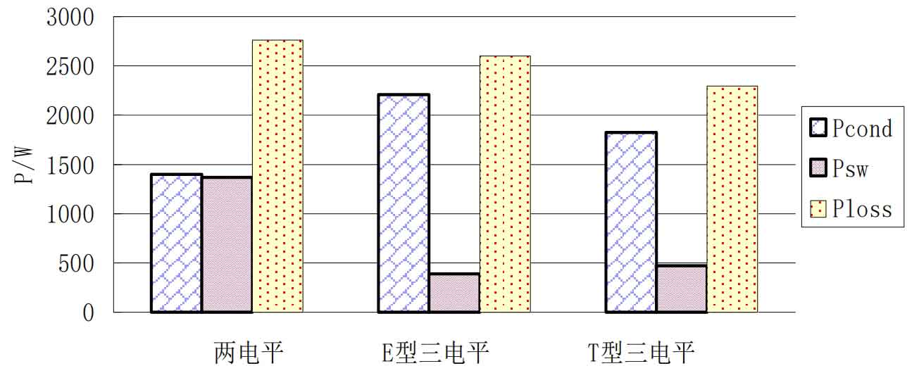
According to Figure 9, the on state losses of E-type three-level and T-type three-level solar inverters are about 1.6 times and 1.3 times that of two-level solar inverters, respectively, and T-type on state losses only account for 82.7% of E-type solar inverters. This is because the switch devices of the traditional two-level structure are significantly less than the other two three-level structures, resulting in less current flowing through the switch devices, which makes the two-level solar inverter have smaller on state losses. At the same time, the E-type solar inverter has more switching devices than the T-type, so the loss is relatively greater when the switching devices are conducting. Compared to switching losses, the switching losses of E-type three-level and T-type three-level solar inverters only account for 28.4% and 34.4% of the two-level, and the E-type switching losses are the smallest. This is because the three-level solar inverter has an additional zero potential output compared to the two-level solar inverter, causing the voltage stress of the switching device to be half of the two-level, resulting in a significant reduction in switching losses.
According to the technical specifications for photovoltaic grid connected inverters (NB/T3204-2013), the maximum junction temperature of the power switch IGBT chip is 120 ℃ as the inverter design standard, which requires that the maximum Tj value of the switch tube should not exceed 120 ℃ during normal operation. According to the thermal resistance calculation formula, under the same operating conditions, the losses and heat sink thermal resistance values of the three types of inverters are shown in Table 5.
| Type | Total loss (Ploss/W) | Permissible temperature of radiator (Ts/℃) | Temperature rise (ΔT/℃) | Radiator thermal resistance (Rtf/℃ · W^-1) | Efficiency( η/%) |
| Two level | 2766.00 | 67 | 27 | 0.029 | 97.79 |
| E-type three-level | 2599.74 | 72 | 32 | 0.037 | 97.92 |
| T-type three-level | 2294.40 | 92 | 52 | 0.068 | 98.20 |
According to Table 5, traditional two-level solar inverters have the highest total power loss and the lowest allowable temperature and thermal resistance of the heat sink. This indicates that a two-level solar inverter has the highest power loss and higher requirements for heat sinks, resulting in higher technical requirements and costs for heat sinks. The solar inverters with E-type three-level and T-type three-level structures have power losses of 93.99% and 82.95% of the two-level structure, and the thermal resistance of the heat sink is 1.28 and 2.35 times that of the two-level structure. This indicates that the three-level structure has smaller power losses and lower heat sink requirements, and the cost of the heat sink is lower. Compared to the E-type three-level and T-type three-level solar inverters, the T-type has a power loss of 305.34W less than the E-type, and the allowed temperature of the heat sink is 20 ℃ higher, with a thermal resistance value of 0.031, indicating that under the same three-level solar inverter conditions, the T-type topology structure has smaller power loss and lower heat sink requirements. At the same time, the T-type three-level solar inverter adopts a copper free substrate packaging, which has better heat dissipation effect, and the heat sink cost can be reduced by nearly 30%. Compared with the output efficiency of the three solar inverters, it can be seen that the T-type solar inverter has the highest efficiency, reaching 98.2%, which is 0.41 and 0.28 percentage points higher than the other two solar inverters, indicating that the T-type solar inverter can better meet the requirements of efficiency improvement.
In order to improve the conversion efficiency of solar inverters, how to better reduce power loss and device costs has become the main direction of research on solar inverters. Traditional two-level solar inverters have fewer switching devices, but power loss and harmonic distortion are larger, requiring higher requirements for heat sinks and filters. Compared to E-type and T-type three-level structures, T-type switching devices are fewer and have relatively less power loss. They have lower requirements for heat sinks, filters, and other devices, higher efficiency, and are more suitable for high-power, high switching frequency photovoltaic power generation requirements. Therefore, T-type three-level structures are more competitive in the photovoltaic industry.
When constructing the photovoltaic power generation system, a T-type three-level structure solar inverter was selected, and the switching frequency of the power module was selected as 8kHz, not 5kHz as compared to the experimental results. This is because for T-type three-level solar inverters, a switching frequency of 8kHz is more efficient than a switching frequency of 5kHz, with better harmonic characteristics and lower temperature requirements. Therefore, the requirements for equipment such as reactors and heat sinks are relatively lower, which correspondingly reduces the cost of the entire system.
3. Summary
This chapter first analyzes the working principles and characteristics of traditional two-level, E-type three-level, and T-type three-level solar inverters, and then compares the power loss and temperature situation of the three types of solar inverters through semi physical simulation experiments. According to the experimental results, it was found that under the same operating conditions, there are certain differences in the switching losses and on state losses of the three solar inverter structures, and the power loss of the three-level structure solar inverter is lower than that of the traditional two-level structure solar inverter, requiring lower equipment for heat sinks and filters. In three-level solar inverters, the T-shaped structure is superior to the E-shaped structure in terms of power loss, heat sink and filter requirements, so it can better meet the current development requirements of high-power and high switching frequency solar inverters.