
In my research, I have extensively investigated the impact of lithium bis(fluorosulfonyl)imide (LiFSI) content in the electrolyte on the performance of lithium iron phosphate (LiFePO4) batteries. LiFePO4 batteries are renowned for their high safety, long cycle life, and cost-effectiveness, making them a preferred choice for electric vehicles and energy storage systems. However, their performance can be limited by factors such as electrolyte composition, particularly the choice of lithium salts. Traditionally, lithium hexafluorophosphate (LiPF6) has been the dominant lithium salt due to its balanced properties, but it suffers from issues like thermal instability and sensitivity to moisture. In contrast, LiFSI offers superior thermal stability, higher conductivity, and better compatibility with electrodes. Therefore, in this study, I aimed to optimize the LiFSI content in mixed lithium salt electrolytes to enhance the overall performance of LiFePO4 batteries while considering cost implications.
The electrolyte in a LiFePO4 battery typically consists of carbonate solvents, lithium salts, and additives. The lithium salt plays a crucial role in determining ionic conductivity, electrochemical stability, and interfacial properties. LiPF6, while widely used, decomposes at elevated temperatures, producing corrosive by-products like PF5 and HF, which can degrade battery life and safety. On the other hand, LiFSI has a higher decomposition temperature (above 200°C) and exhibits excellent ionic conductivity due to its larger anion radius, facilitating lithium-ion dissociation. However, LiFSI is more expensive than LiPF6, prompting the need for a balanced approach by mixing both salts. In my work, I systematically varied the LiFSI content in the electrolyte and evaluated its effects on high-temperature cycling, rate capability, high-temperature storage, and low-temperature cycling of LiFePO4 batteries.
To begin, I prepared soft-pack LiFePO4 batteries with a nominal capacity of 3.0 Ah. The positive electrode comprised LiFePO4 as the active material, coated on carbon-coated aluminum foil, while the negative electrode used artificial graphite on copper foil. The separator was a polyethylene-based ceramic-coated membrane. The electrolytes were formulated with varying proportions of LiPF6 and LiFSI, as detailed in Table 1, with a solvent mixture of dimethyl carbonate (DMC), ethyl methyl carbonate (EMC), and ethylene carbonate (EC) in a volume ratio of 3:4:3. This setup allowed me to control the LiFSI content while maintaining overall lithium salt concentration.
| Scheme | LiPF6 Content (wt%) | LiFSI Content (wt%) | Solvent Volume Ratio |
|---|---|---|---|
| 0% LiFSI | 13 | 0 | DMC:EMC:EC = 3:4:3 |
| 3% LiFSI | 10 | 3 | DMC:EMC:EC = 3:4:3 |
| 6% LiFSI | 7 | 6 | DMC:EMC:EC = 3:4:3 |
| 9% LiFSI | 4 | 9 | DMC:EMC:EC = 3:4:3 |
The ionic conductivity of the electrolyte is a key parameter influencing battery performance. I measured the conductivity as a function of LiFSI content, and the results showed a linear increase with higher LiFSI proportions. This can be attributed to the larger ionic radius of the bis(fluorosulfonyl)imide anion (FSI⁻) compared to the hexafluorophosphate anion (PF₆⁻), which reduces the binding energy with lithium ions (Li⁺) and enhances dissociation. The relationship can be expressed using the Arrhenius equation for ionic conductivity: $$ \sigma = A e^{-E_a / (kT)} $$ where $\sigma$ is the conductivity, $A$ is a pre-exponential factor, $E_a$ is the activation energy, $k$ is Boltzmann’s constant, and $T$ is the temperature. With increasing LiFSI content, $E_a$ decreases, leading to higher $\sigma$ values. This improvement in conductivity directly benefits the electrochemical kinetics in LiFePO4 batteries.
To assess the electrochemical behavior, I performed cyclic voltammetry (CV) on the LiFePO4 batteries. The CV curves revealed that as LiFSI content increased, the peak separation between oxidation and reduction decreased, indicating enhanced reversibility of lithium-ion insertion and extraction reactions. This reduction in polarization is critical for minimizing energy losses during charge-discharge cycles. The peak current ($I_p$) in CV can be related to the diffusion coefficient ($D$) via the Randles-Sevcik equation: $$ I_p = 0.4463 n F A C \sqrt{\frac{n F v D}{R T}} $$ where $n$ is the number of electrons transferred, $F$ is Faraday’s constant, $A$ is the electrode area, $C$ is the concentration, $v$ is the scan rate, $R$ is the gas constant, and $T$ is the temperature. The decrease in polarization with higher LiFSI content suggests improved $D$ values, contributing to better performance in LiFePO4 batteries.
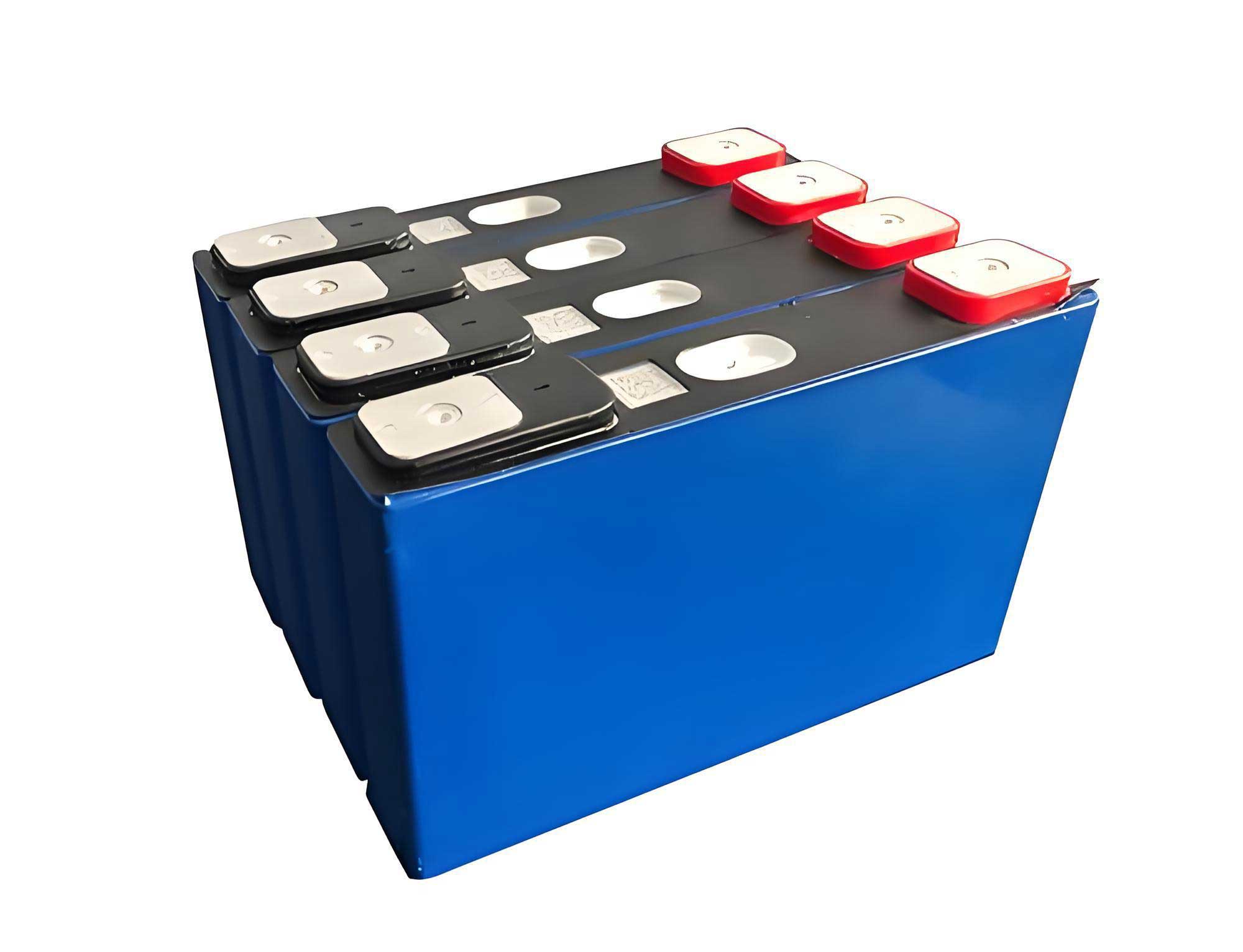
Next, I evaluated the direct current internal resistance (DCR) of the LiFePO4 batteries at different states of charge (SoC). The DCR is a measure of ohmic and polarization resistances during operation. As shown in Table 2, the DCR decreased with increasing LiFSI content across all SoC levels. For instance, at 80% SoC, the DCR reduction was approximately 2% for the 9% LiFSI scheme compared to the baseline. This reduction aligns with the lower interfacial impedance facilitated by LiFSI, which forms a more stable and conductive solid electrolyte interphase (SEI) on the graphite anode. The DCR can be modeled as: $$ \text{DCR} = R_{\text{ohm}} + R_{\text{ct}} + R_{\text{diff}} $$ where $R_{\text{ohm}}$ is the ohmic resistance, $R_{\text{ct}}$ is the charge transfer resistance, and $R_{\text{diff}}$ is the diffusion resistance. The incorporation of LiFSI primarily reduces $R_{\text{ct}}$ by enhancing electrode-electrolyte interactions.
| Scheme | DCR Reduction at 20% SoC (%) | DCR Reduction at 50% SoC (%) | DCR Reduction at 80% SoC (%) |
|---|---|---|---|
| 3% LiFSI | 0.6 | 0.2 | 0.4 |
| 6% LiFSI | 1.0 | 1.1 | 1.1 |
| 9% LiFSI | 1.6 | 1.9 | 2.4 |
High-temperature cycling performance is crucial for the durability of LiFePO4 batteries in real-world applications. I conducted cycle tests at 45°C with a 100% depth of discharge (DOD). The capacity retention after 800 cycles improved significantly with higher LiFSI content, as summarized in Table 3. For the 9% LiFSI scheme, the capacity retention reached 93.1%, which is 1.4% higher than the baseline. This enhancement can be explained by the superior thermal stability of LiFSI, which mitigates decomposition reactions and reduces acid generation. Consequently, fewer side reactions occur at the electrodes, preserving active lithium and maintaining structural integrity in the LiFePO4 battery. The capacity fade over cycles can be described by a empirical model: $$ Q_{\text{retention}} = Q_0 – k \sqrt{N} $$ where $Q_0$ is the initial capacity, $k$ is a degradation rate constant, and $N$ is the cycle number. With LiFSI addition, $k$ decreases, leading to slower capacity loss.
| Scheme | Capacity Retention after 800 Cycles at 45°C (%) | Improvement over Baseline (%) |
|---|---|---|
| 0% LiFSI | 91.7 | 0 |
| 3% LiFSI | 92.0 | 0.3 |
| 6% LiFSI | 92.5 | 0.8 |
| 9% LiFSI | 93.1 | 1.4 |
Rate capability testing revealed the ability of LiFePO4 batteries to deliver high currents. I discharged the batteries at various C-rates (0.2C to 3C) and calculated the capacity retention relative to the 0.2C discharge. The results, presented in Table 4, demonstrate that increasing LiFSI content enhances rate performance, especially at higher currents. For the 9% LiFSI scheme, the capacity retention at 3C improved by 1.58% compared to the baseline. This is attributed to the higher ionic conductivity and reduced polarization, which facilitate faster lithium-ion transport during high-rate discharges. The power capability of a LiFePO4 battery can be estimated using the Peukert’s law: $$ I^n t = C $$ where $I$ is the discharge current, $t$ is the time, $n$ is the Peukert exponent, and $C$ is the capacity. With LiFSI, $n$ approaches 1, indicating less capacity loss at high currents.
| Scheme | Capacity Retention at 1C (%) | Capacity Retention at 2C (%) | Capacity Retention at 3C (%) |
|---|---|---|---|
| 0% LiFSI | 94.77 | 90.46 | 89.23 |
| 3% LiFSI | 94.85 | 91.08 | 90.10 |
| 6% LiFSI | 95.11 | 91.40 | 90.29 |
| 9% LiFSI | 95.25 | 91.75 | 90.81 |
Low-temperature cycling performance is another critical aspect, especially for electric vehicles operating in cold climates. I tested the LiFePO4 batteries at 0°C with a charge rate of 0.2C and discharge rate of 0.33C. The initial discharge capacity increased with LiFSI content, from 2.71 Ah for 0% LiFSI to 2.81 Ah for 9% LiFSI, indicating improved low-temperature charging efficiency. After 50 cycles, the capacity retention also improved, as shown in Table 5. Moreover, visual inspection of the anode surfaces revealed reduced lithium plating for higher LiFSI schemes, with the 9% LiFSI anode appearing golden without visible dendrites. This benefit stems from the lower SEI impedance enabled by LiFSI, which enhances lithium-ion diffusion kinetics at low temperatures. The diffusion coefficient temperature dependence can be expressed as: $$ D = D_0 e^{-E_a / (RT)} $$ where $D_0$ is a pre-exponential factor. LiFSI lowers $E_a$, increasing $D$ even at reduced temperatures.
| Scheme | Initial Discharge Capacity at 0°C (Ah) | Capacity Retention after 50 Cycles (%) | Anode Surface Condition |
|---|---|---|---|
| 0% LiFSI | 2.71 | 92.99 | Severe lithium plating |
| 3% LiFSI | 2.75 | 93.82 | Moderate lithium plating |
| 6% LiFSI | 2.78 | 93.88 | Minor lithium plating |
| 9% LiFSI | 2.81 | 93.95 | No visible lithium plating |
High-temperature storage tests were conducted at 60°C for 28 days to evaluate the long-term stability of LiFePO4 batteries. The results, summarized in Table 6, show that higher LiFSI content reduced voltage drop and internal resistance growth after storage. The residual capacity rate and recovery capacity rate improved, with the 9% LiFSI scheme showing a 0.56% increase in residual capacity and a 0.89% increase in recovery capacity compared to the baseline. Electrochemical impedance spectroscopy (EIS) analysis, as depicted in Figure 6, confirmed that the charge transfer resistance ($R_{ct}$) growth was suppressed with LiFSI addition. For instance, the $R_{ct}$增长率 decreased from 77.3% for 0% LiFSI to 21.7% for 9% LiFSI. This indicates that LiFSI forms a more robust SEI layer, minimizing side reactions and preserving electrode interfaces during storage. The impedance can be modeled using an equivalent circuit: $$ Z = R_s + \frac{1}{j\omega C_{dl} + 1/R_{ct}} + Z_w $$ where $R_s$ is the series resistance, $C_{dl}$ is the double-layer capacitance, $\omega$ is the angular frequency, and $Z_w$ is the Warburg impedance for diffusion.
| Scheme | Voltage Drop after Storage (mV) | Internal Resistance Growth (mΩ) | Residual Capacity Rate (%) | Recovery Capacity Rate (%) |
|---|---|---|---|---|
| 0% LiFSI | 60 | 0.4 | 93.41 | 94.79 |
| 3% LiFSI | 56 | 0.4 | 93.45 | 94.80 |
| 6% LiFSI | 55 | 0.3 | 93.75 | 95.26 |
| 9% LiFSI | 54 | 0.2 | 93.97 | 95.68 |
To delve deeper into the mechanisms, I considered the role of LiFSI in SEI formation. The SEI layer on graphite anodes is crucial for preventing continuous electrolyte decomposition and lithium loss. LiFSI, due to its electrochemical stability, facilitates the formation of a thin and conductive SEI rich in inorganic components like LiF. This can be represented by the reduction reaction: $$ \text{FSI}^- + 2e^- + 2\text{Li}^+ \rightarrow \text{LiF} + \text{LiSO}_2\text{F} + \text{other products} $$ In contrast, LiPF6 decomposition leads to more resistive organic species. The improved SEI properties with LiFSI contribute to the enhanced performance across all tests for the LiFePO4 battery.
Furthermore, the synergistic effects of mixed lithium salts should be highlighted. By combining LiPF6 and LiFSI, I leveraged the cost-effectiveness of LiPF6 and the performance benefits of LiFSI. The optimal LiFSI content of 9% represents a balance where significant improvements are achieved without excessive cost increases. This approach is particularly relevant for scaling up LiFePO4 battery production for commercial applications.
In terms of mathematical modeling, the performance enhancements can be quantified using degradation models. For instance, the capacity fade during cycling can be fitted to a linear model: $$ \Delta Q = \alpha + \beta N $$ where $\Delta Q$ is the capacity loss, $\alpha$ is the initial loss due to SEI formation, $\beta$ is the cyclic degradation rate, and $N$ is the cycle number. With higher LiFSI content, both $\alpha$ and $\beta$ decrease, indicating slower degradation. Similarly, for storage, the self-discharge rate can be expressed as: $$ Q_{\text{residual}} = Q_0 e^{-k_s t} $$ where $k_s$ is the self-discharge rate constant and $t$ is time. LiFSI reduces $k_s$, leading to better capacity retention.
Additionally, I explored the impact of LiFSI on the cathode-electrolyte interface in LiFePO4 batteries. LiFePO4 is known for its stable olivine structure, but electrolyte oxidation can still occur at high voltages. LiFSI, with its higher anodic stability, minimizes oxidative decomposition, reducing transition metal dissolution from the cathode. This contributes to the improved high-temperature cycling and storage performance. The overall cell voltage can be described by the Nernst equation: $$ E = E^0 – \frac{RT}{nF} \ln Q $$ where $E$ is the cell potential, $E^0$ is the standard potential, and $Q$ is the reaction quotient. Stable interfaces help maintain $E$ close to $E^0$ over time.
To summarize, my investigation demonstrates that increasing LiFSI content in the electrolyte significantly enhances the performance of LiFePO4 batteries. Key findings include reduced DCR, improved high-temperature cycle life, better rate capability, enhanced low-temperature charging, and superior high-temperature storage stability. The 9% LiFSI scheme emerged as the optimal formulation, offering a practical trade-off between performance and cost. These results underscore the importance of lithium salt selection in advancing LiFePO4 battery technology for next-generation energy storage solutions.
Future work could focus on long-term cycling beyond 800 cycles, safety tests under abusive conditions, and economic analyses of large-scale implementation. Moreover, combining LiFSI with novel additives or solvent blends may further push the boundaries of LiFePO4 battery performance. As the demand for efficient and durable energy storage grows, optimizing electrolyte compositions will remain a critical research avenue for LiFePO4 batteries.
In conclusion, through systematic experimentation and analysis, I have validated the positive effects of LiFSI on LiFePO4 battery performance. This study provides valuable insights for battery engineers and researchers aiming to develop high-performance LiFePO4 batteries for various applications. The integration of LiFSI into electrolytes represents a promising strategy to overcome limitations associated with traditional lithium salts, paving the way for more reliable and efficient LiFePO4 battery systems.