
The rapid global transition towards renewable energy integration necessitates robust and large-scale energy storage solutions. Within this landscape, lithium iron phosphate (LiFePO4) batteries have emerged as a dominant technology for stationary energy storage systems (ESS) due to their intrinsic safety, long cycle life, and environmental friendliness compared to other lithium-ion chemistries. However, under extreme abuse conditions such as overcharging, even lifepo4 battery systems can undergo thermal runaway—a dangerous chain reaction involving heat and gas generation that can lead to fire or explosion. This article, from a first-person research and development perspective, delves into the gas generation mechanisms during overcharge-induced thermal runaway of lifepo4 battery packs, presents experimental validation, and proposes a comprehensive early-warning monitoring system based on gas particle concentration detection.
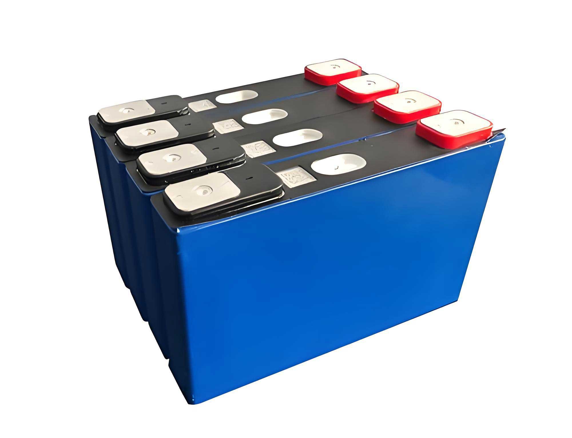
The fundamental appeal of the lifepo4 battery lies in its stable olivine crystal structure. During normal operation, lithium ions move between the anode and cathode through the electrolyte. The primary electrochemical reactions for a lifepo4 battery are as follows.
Normal Charging/Discharging:
At the cathode (positive electrode during discharge):
$$ \text{LiFePO}_4 \rightleftharpoons \text{FePO}_4 + \text{Li}^+ + e^- $$
At the anode (negative electrode during discharge, typically graphite):
$$ \text{C}_6 + \text{Li}^+ + e^- \rightleftharpoons \text{LiC}_6 $$
The overall reaction is:
$$ \text{LiFePO}_4 + \text{C}_6 \rightleftharpoons \text{FePO}_4 + \text{LiC}_6 $$
This reversible reaction is the basis for the stable cycling of a lifepo4 battery.
However, during overcharging, this balance is severely disrupted. The sequence of gas-generating reactions is critical for understanding monitoring strategies. A summary of the key stages and reactions is presented below.
| Stage | Condition | Primary Chemical Reactions & Gas Products | Observable Phenomena |
|---|---|---|---|
| Stage 1: Initial Overcharge | Lithium plating begins; electrolyte decomposition. | $$ \text{Li}^+ + e^- \rightarrow \text{Li}(s) \text{ (plating)} $$ Electrolyte (LiPF6) hydrolysis: $$ \text{LiPF}_6 + \text{H}_2\text{O} \rightarrow \text{LiF} + \text{POF}_3 + 2\text{HF} $$ Generation of HF, POF3. | Minor pressure increase, possible early venting. |
| Stage 2: Severe Overcharge & Decomposition | Complete lithium intercalation sites filled; severe electrolyte oxidation. | Oxidation of carbonate solvents (EC, PC, DMC): $$ \text{C}_3\text{H}_4\text{O}_3 (\text{PC}) + [\text{O}] \rightarrow \text{CO}_2 + \text{C}_2\text{H}_4 + \text{H}_2\text{O} $$ Significant generation of CO2, CO, C2H4, H2. | Significant “swelling” or “bulging,” safety valve opening, white smoke. |
| Stage 3: Thermal Runaway & Combustion | Exothermic reactions cause rapid temperature rise (>200°C). | Decomposition of SEI layer, reaction of plated lithium with electrolyte: $$ 2\text{Li} + \text{C}_3\text{H}_4\text{O}_3 \rightarrow \text{Li}_2\text{CO}_3 + \text{C}_2\text{H}_4 $$ Further combustion of released gases (H2, CO, hydrocarbons) with oxygen. | Open flame, intense heat, thick black smoke, potential explosion. |
To empirically validate these mechanisms and gather quantitative data for system design, a controlled overcharge test was conducted on a commercial 100Ah prismatic (hard-case) lifepo4 battery cell. The experimental setup included a thermal chamber, a programmable DC power supply for constant-current overcharging, an array of K-type thermocouples, an FTIR (Fourier Transform Infrared) gas analyzer, and a standard video monitoring system.
The cell was overcharged at a 1C rate (100A) from its nominal voltage until catastrophic failure. The temporal profile of key parameters is summarized below.
| Time Elapsed (s) | Cell Surface Temp. (°C) | Key Gas Concentration Trends | Observable Event |
|---|---|---|---|
| 0 – 800 | 25 ~ 45 | Background levels. Slight, steady increase in CO2 and H2 detected by ~600s. | Normal overcharge, mild heating. |
| ~800 | ~55 | Pronounced spike in H2 concentration. CO begins to rise. | Safety valve opens (first venting). |
| 800 – 2400 | 55 ~ 180 | Steady, exponential increase in H2, CO, CO2. HF and other VOCs detected. | Cell bulging visibly. Emission of white smoke begins. |
| ~2400 | ~180 (peak before drop) | Gas concentrations plateau briefly as venting intensifies. | Intense white smoke obscures view. Bulging severe. |
| 2400 – 2600 | 180 -> 250+ | Second sharp rise in all combustible gas (H2, CO) concentrations. | Smoke density increases, infrared shows intense heat. |
| ~2600 | >300 | Sudden change in gas composition, oxygen depletion noted. | Ignition and open flame. |
The critical insight from this experiment is the continuous and early evolution of gas species, particularly hydrogen (H2) and carbon monoxide (CO), well before the appearance of visible smoke or flame. The temperature rise, while significant, is a lagging indicator compared to the early gas release. This forms the cornerstone of the proposed early-warning strategy: detecting the subtle changes in airborne particle and gas concentrations that precede catastrophic failure in a lifepo4 battery pack.
The proposed monitoring system is designed for deployment in containerized or room-based lifepo4 battery energy storage systems. Its architecture is modular, scalable, and focuses on early detection to enable preventive intervention.
The core detection principle is based on Mie scattering theory, which describes how light is scattered by particles with a diameter similar to or larger than the light’s wavelength. The gas and aerosol particles released from a failing lifepo4 battery effectively create a “haze” of such particles. The system uses a laser diode and a photodetector arranged at a specific angle (often near 0° for simplified, high-sensitivity detection of total particle concentration).
The scattering intensity \( I_s \) is given by:
$$ I_s = I_0 \frac{\lambda^2}{8\pi^2 r^2} \left| S(\theta, d, m) \right|^2 N $$
Where:
\( I_0 \) is the incident laser intensity,
\( \lambda \) is the wavelength of the laser light,
\( r \) is the distance from the scattering volume to the detector,
\( S(\theta, d, m) \) is the complex scattering amplitude function dependent on scattering angle \( \theta \), particle diameter \( d \), and complex refractive index \( m \),
\( N \) is the number density of particles in the scattering volume.
For a fixed, calibrated sensor geometry and a known typical particle size distribution from initial lifepo4 battery venting, the equation simplifies. The detected signal \( V_{out} \) is proportional to the particle concentration change \( \Delta N \):
$$ V_{out} = k \cdot \Delta N + V_{baseline} $$
Here, \( k \) is a system constant determined during calibration, and \( V_{baseline} \) is the output under normal, clean air conditions. The system continuously monitors \( \Delta V_{out} \) (the deviation from a dynamically adjusted baseline) and triggers alerts based on configurable thresholds related to rate-of-change and absolute level.
| Module Name | Primary Components | Function |
|---|---|---|
| Field Monitoring Terminal | Laser-based aerosol sensor, H2/CO electrochemical sensors, Temp/Humidity sensor, Microcontroller, Power supply, Communication interface (RS-485/ Ethernet). | Installed in the ESS enclosure. Continuously samples air via an internal pump. Pre-processes sensor data (filtering, A/D conversion). Transmits data packets to the master station. |
| Data Acquisition & Preprocessing | Communication gateways, Data buffer, Time synchronization service. | Aggregates data from multiple terminals. Performs initial data validation and timestamp alignment. |
| Core Analytics & Warning Logic | Cloud/Edge server running analysis algorithms (e.g., trend analysis, machine learning models). Database for historical data. | Calculates gas concentration trends and particle count derivatives. Compares real-time data against multi-threshold models (static thresholds, rate-of-rise). Executes warning logic to distinguish between normal fluctuation and fault conditions. |
| Alert & Human-Machine Interface (HMI) | SMS/Email gateways, Visual dashboard, Audible/visual alarms on-site. | Generates staged alerts (Pre-Warning, Warning, Critical). Sends notifications to operators. Displays system status and fault location on a central monitor. |
| Integration & Control Interface | Programmable Logic Controller (PLC) with digital I/O, Standard protocols (Modbus TCP, MQTT). | Provides relay outputs to trip the ESS main circuit breaker, activate ventilation systems, or trigger fire suppression in later stages. Allows integration with broader Building Management Systems (BMS). |
The system’s algorithm operates in distinct phases, corresponding to the failure stages of a lifepo4 battery.
| System Phase | Detected Condition | Action | Goal |
|---|---|---|---|
| Phase 0: Normal Operation | Particle count and gas concentrations stable at baseline. Temperature normal. | Continuous logging. Adaptive baseline calibration to account for ambient dust. | Establish a reliable reference point. |
| Phase 1: Pre-Warning (Early Fault) | Sustained increase in particle count (>X% above baseline) and/or slight rise in H2 levels. No temperature anomaly. | Internal flag set. Data trend is highlighted on HMI. No external alarm. | Notify operators of a potential early issue for investigation during next inspection. |
| Phase 2: Warning (Active Decomposition) | Rapid rate-of-rise in particle count and H2/CO concentrations. Temperature begins to show a slight upward trend. | Audible/visual alarm at local HMI. SMS/email alert sent to designated personnel. Ventilation system may be activated automatically. | Prompt immediate operator investigation and manual intervention to locate and isolate the affected lifepo4 battery string or module. |
| Phase 3: Critical (Imminent Thermal Runaway) | Particle and combustible gas concentrations exceed absolute safety thresholds. Temperature rising rapidly. | Critical alarm. Automatic commands sent via control interface to: 1) Trip the ESS AC/DC disconnects, 2) Activate enhanced ventilation/fire suppression pre-activation, 3) Lock out the system. | Prevent propagation, protect assets, and ensure personnel safety. Minimize damage. |
Compared to traditional protection methods that rely solely on voltage and temperature monitoring, this gas-based approach offers a significant advantage in early detection time. Voltage may only show anomalies at a very late stage of overcharge, and temperature sensors require thermal propagation from the cell core to the surface, which introduces lag. The release of gas, however, is a direct byproduct of the internal electrochemical decomposition and occurs at the very onset of the failure process in a lifepo4 battery.
In conclusion, the thermal runaway of lifepo4 battery packs under overcharge conditions follows a predictable sequence marked by the continuous generation of characteristic gases and aerosols. Experimental data confirms that gas concentration changes provide the earliest detectable signature of failure, preceding significant temperature rise and visible smoke. The proposed monitoring system, leveraging Mie scattering theory and electrochemical gas sensing, is designed to capture these subtle initial changes. Through its modular architecture and multi-stage warning logic, it enables “Phase 1” or “Phase 2” interventions, potentially allowing maintenance personnel to address a fault before it escalates into a critical fire event. This proactive, gas-centric monitoring strategy represents a vital layer of safety enhancement for modern lifepo4 battery energy storage systems, safeguarding both infrastructure and the broader adoption of this critical energy storage technology.