
The high proportion of renewable energy integration has brought new challenges to the safe and stable operation of the power system, and energy storage systems are of great significance in maintaining the quality of power grid energy and improving the reliability of the power system. Battery Energy Storage System (BESS) has the advantages of high energy density and high electrical efficiency, and the rapid development of electric vehicles has driven the progress of battery related technologies, making batteries widely used in the field of electric energy storage. However, with the continuous occurrence of battery energy storage safety accidents, the safety of energy storage systems has become a key factor restricting the development of battery energy storage. In addition, as a large number of power batteries reach their retirement age, how to achieve the cascade utilization of retired power batteries has become an urgent problem for the battery industry to solve. The safety and economic issues of energy storage systems ultimately stem from the “short board effect” of battery systems, where the overall performance of the battery network depends on the worst performing battery cells in the network. Therefore, how to fundamentally eliminate the “short board effect” of battery systems is the core issue in the development of the energy storage industry.
In order to overcome the “short board effect” of battery systems, the existing technical system mainly starts from two aspects. One is to pursue the consistency of battery monomers, continuously narrowing the differences between battery monomers through processes, technologies, sorting, grouping, and other means to meet the requirements of battery system consistency. However, the marginal effect of pursuing consistency is decreasing, especially for the cascade utilization technology of retired power batteries. With the improvement of battery consistency requirements, the cost of sorting and restructuring retired batteries also increases. In addition, even though the battery cells maintain consistency at the factory, there are differences in the working environment of different cells during operation. This difference will continue to accumulate and amplify during the charging and discharging cycles, and the problem of “short board effect” is still difficult to avoid. Another approach is to design equalization methods for battery networks, which are mainly divided into two categories: passive equalization [9] and active equalization. The existing technology route mainly focuses on active balancing, constructing additional energy transmission channels through devices such as capacitors, inductors, transformers, and power electronic converters to achieve the transfer of battery energy between different units. However, battery networks based on active balancing often adopt a “series only, not parallel” approach to form battery clusters. Multiple battery clusters need to be connected in parallel to provide sufficient output capacity, and the parallel connection between battery clusters can cause circulation problems. In addition, existing research on active balancing methods mainly focuses on power electronic converters, which often operate at a frequency of kilohertz. During the high-frequency disconnection process of power electronics, additional switching losses will be introduced, reducing the energy efficiency of the battery system.
Just like ‘there are no two identical leaves in the world’, the differences between different battery cells are inevitable, that is, the difference is absolute, and the consistency is relative. Therefore, how to accept and manage battery differences is an inevitable requirement for the development of battery energy storage systems. Recently, thanks to the rapid development of power semiconductor devices, Dynamic Reconfigurable Battery Network (DRBN) has been able to disperse and digitize continuous energy flow at the kilowatt level, transforming traditional analog battery energy storage systems into new digital energy storage systems, providing a new path to improve the safety and consistency of energy storage systems. However, existing research mainly focuses on theoretical analysis and prototype verification, lacking operational analysis and data validation of large-scale dynamic reconfigurable battery energy storage systems. In addition, the safety, reliability, and control effectiveness of dynamic reconfigurable energy storage systems under actual operating conditions are still unclear.
In view of this, this article analyzes the principles and applications of large-scale dynamic reconfigurable battery energy storage systems based on actual operational data. Firstly, starting from the basic idea of energy digitization, the principle and architecture of a dynamic reconfigurable battery energy storage system are elaborated; Then, energy control and system level intrinsic safety control methods based on dynamic reconfigurable battery energy storage technology were proposed respectively; Next, the actual operating data of the energy storage system was analyzed, and the performance of the dynamic reconfigurable battery energy storage system was verified from the aspects of State of Charge (SOC) balance, integrated control of electric and thermal systems, and safe operation; Finally, a series of misconceptions in the design process of battery energy storage systems were deeply explored around issues such as “large and small”, “high and low”, and “new and old”.
1. Architecture of Dynamic Reconfigurable Battery Energy Storage System
1.1 Basic idea of energy digitization
With the rapid development of low-voltage and low-power power electronic devices, the concept of constructing a dynamic reconfigurable battery energy storage system based on energy digitization has become possible. Traditional battery management systems usually use IGBT to achieve battery energy control, which has the characteristics of high voltage, high current, and high power. The minimum control unit of DRBN is the module level, which has the characteristics of low voltage and low current, so it is very suitable for the typical application scenarios of MOSFTE. Table 1 provides a comparison of the performance between MOSFETs and IGBTs, where MOSFETs have smaller on-resistance and on state losses. In addition, compared to IGBT, low-voltage low-power MOSFETs have a lower price and a stronger price advantage when building large-scale battery energy storage systems.
| Indicators | Low voltage and low power MOSFET | IGBT |
| Voltage | 50V~200V | 0.6kV~6.5kV |
| Current | 100A~200A | 750A~3600A |
| Switching frequency | Up to several hundred kHz | Up to tens of kHz |
| Conduction resistance | 1m Ω~8m Ω | <400m Ω |
| Cost | $1~$3 | $4~$12 |
The DRB energy storage system is a distributed low-voltage system, in which the maximum voltage borne by MOSFETs in the off state does not exceed the working voltage of the battery module, with typical values ranging from a few volts to several tens of volts, greatly improving operational safety during installation and maintenance. In addition, the maximum operating current of MOSFETs will not exceed the maximum current of the battery module, with typical values ranging from tens to hundreds of amperes. On the other hand, the reconstruction frequency of DRBN is at the Hertz level, which is much lower than the switching frequency of 100kHz level in current power electronic converters. Therefore, compared to the power electronic converters used in traditional equalization circuits, DRBN can effectively reduce the loss of energy management systems and improve the energy efficiency of battery energy storage systems.

The basic idea of DRBN is fundamentally different from the battery balancing approach of traditional BMS. The capacity of a battery can be expressed as the product of current and time. Traditional battery balancing schemes start from the perspective of current and control the capacity by adjusting the current flowing through the battery cell. DRBN achieves a “best effort” battery energy management mode from the perspective of time, namely Δ 𝐶=𝐼 × Δ 𝑡, (1) where, Δ 𝑡 represents the time when the battery is connected to the charging and discharging circuit. DRBN schedules and arranges “energy slices” from different battery cells according to the timeline. The larger the available capacity of battery cells, the more time slots they are arranged on the timeline, which means the longer they are connected to the charging and discharging circuit. This time centered battery energy management method adopts a frequency of Hertz level, thereby avoiding switching losses caused by high-frequency power electronic devices.
1.2 System Architecture
Battery energy storage systems typically require a large number of battery cells to be connected in series and parallel to meet the requirements of output voltage and current. However, due to the differences between battery cells, direct parallel connection can lead to circulating currents. Therefore, traditional battery energy storage systems do not allow direct parallel connection of battery cells. Instead, battery cells are connected in series to form battery clusters, which are then paralleled at the cluster level through high-power power electronic converters (DC/DC or DC/AC), as shown in Figure 1. The output end of each battery cluster is connected to a DC/DC converter to achieve DC voltage conversion and energy control of the battery cluster. In addition, to address the issue of inconsistent battery cells, traditional battery energy storage systems require the configuration of active or passive equalization circuits. However, this fixed series connected battery cluster structure cannot achieve precise isolation of faulty batteries. When a certain battery cell in the cluster fails, the entire battery cluster must stop running. Therefore, the battery energy storage system needs to leave sufficient margin in design to prevent the battery cluster caused by the fault and even the entire system from shutting down.

Unlike the traditional fixed series stacked battery management system, DRBN is based on the digitization of battery energy and achieves battery energy discretization through deep coupling between battery cells and low-voltage low-power power electronic devices. It also achieves digital energy management at the battery module level through a digital energy exchange system, as shown in Figure 2. The difference between DRB energy storage systems and traditional battery energy storage systems is that DRBN achieves discretization and digitization of battery energy through on-off switching, and achieves battery energy balance by controlling the charging and discharging time of different battery cells. Therefore, DRBN no longer requires the equalization circuit in traditional battery energy storage systems. In addition, the digital energy exchange system can achieve controllable parallel connection between battery cells, thereby eliminating the circulation problem caused by direct parallel connection of battery cells. The role of the DC/DC link in traditional battery energy storage systems is to control the output of different battery clusters and achieve balanced distribution of charging and discharging power between different clusters. However, in DRBN, controllable parallel connection is achieved between battery cells, eliminating the traditional concept of battery clusters. Therefore, DRBN does not require DC/DC modules, greatly reducing system costs and improving system efficiency.

2. Energy Control of Dynamic Reconfigurable Battery Energy Storage System
2.1 Digital Energy Exchange System

The Digital Energy Switch System (DESS) is a control module of the DRB energy storage system, used to achieve functions such as status monitoring, consistency control, and security protection of the battery network. Its theoretical architecture is shown in Figure 5. DESS has functions such as measurement, calculation, control, and protection. Firstly, the battery data measured by voltage, current, and temperature sensors is transmitted to DESS through a data bus; Next, DESS evaluates the performance of the battery based on known battery status information, such as SOC and State of Health (SOH) estimation; Then, DESS formulates a charging and discharging plan based on the load requirements, enabling the system to achieve battery consistency and thermal safety control while meeting the load requirements. The control signals are sent to various switches through the data bus. In addition, DESS can monitor the abnormal status of the battery network in a timely manner. If the battery experiences electrical, thermal, power abuse, or other abnormal situations, DESS can control the switch to remove the fault in a timely manner.

2.2 Operational optimization methods
The nonlinear effects of battery cells can affect the energy control of the system. Nonlinear effects include current effects and recovery effects. Current effects refer to the decrease in available capacity of battery cells with an increase in current magnification, while recovery effects refer to the small recovery of battery cell capacity when the current suddenly drops to zero. In DRBN, each cell operates in a pulse discharge mode, resulting in more significant current and recovery effects. Considering the nonlinear effects of batteries during the operation control process can help improve the overall performance of the system.
DESS reconstructs the topology connection of the battery network by controlling the disconnection of each MOSDET. The switch state of the battery network can be represented by the switch matrix 𝜗i:

Among them, 𝑆𝑗 represents the switch status in row i and column j, equal to 1 indicates the switch is on, and equal to 0 indicates the switch is off.
The optimization goal of a digital energy exchange system is to achieve energy control and improve the energy efficiency of the system. Assuming the total working time is T, divide the entire work interval into N reconstruction cycles, with each reconstruction cycle having a time of 𝑇𝑠=𝑇/𝑁. At the beginning of the reconstruction cycle, the digital energy exchange system will generate an optimal control strategy based on the current battery state and change the battery topology through a switch array. Due to the short reconstruction cycle time, the load can be considered constant during this time period. 𝜗𝜗 represents the switch state of the i-th reconstruction cycle, ϒ 𝐶𝑗 represents the energy loss matrix of the battery, 𝐶𝑗 represents the energy loss of each battery unit, 𝜓 𝜓 represents the energy recovery matrix of the battery, 𝑅𝑗 represents the energy recovery of each battery unit. Therefore, the energy dissipation matrix of the entire battery system in the i-th cycle can be expressed in the form of a Hadamard product:

Among them, ϒ The forms of 𝜓 and 𝜓 are as follows:

Note that the above analysis describes the net energy loss during the i-th reconstruction cycle, and the total energy loss during the entire charging and discharging cycle can be expressed as:

Therefore, the energy control of a dynamically reconfigurable battery energy storage system can be expressed as an optimization problem. The physical meanings of the two constraint conditions are that the battery cell is not flowing and the output voltage of the battery system is maintained within a reasonable range.

3. System level intrinsic safety control
System level intrinsic safety emphasizes eliminating some hazards at the root and reducing the probability of accidents, rather than minimizing the losses caused by faults after accidents occur. The DRB energy storage system ensures the inherent safety of the energy storage system from three aspects: controllable parallel connection to reduce heat loss, dynamic recombination to prevent heat accumulation, and rapid removal of faulty batteries.
Due to its ability to balance battery modules, DRBN can achieve controllable parallel connection of battery cells, which is an important means to achieve balanced working current levels and eliminate circulating currents. Theoretical analysis shows that for n parallel systems, the heating power of DRBN is 1/^ 3 of that of traditional battery networks. This indicates that the flexible connection method of DRBN can effectively reduce the heat generation power of battery cells, suppress temperature rise, and thus reduce the probability of faults occurring. In addition, controllable parallel technology can fundamentally eliminate the risk of thermal accumulation and thermal runaway of battery cells. As shown in Figure 6, the individual differences in battery cells in traditional fixed series battery energy storage systems can lead to temperature inconsistency. The DRBN will adaptively adopt a N to k control strategy based on the load situation, that is, select k from N parallel battery cells to access the system. Unselected battery cells have no current flowing through them and do not generate new heat. Therefore, during idle time, the battery cells can dissipate heat and avoid heat accumulation. In addition to controllable parallel connection at the battery cell level, DRBN can also achieve controllable series connection of battery cells, that is, selecting any number of battery cells in the series direction to connect to the system. Controllable series connection can eliminate battery differences in the dimension of series connection, which helps to achieve intelligent operation and maintenance of battery energy storage systems.

In addition to achieving thermal control through controllable series parallel technology, digital energy exchange systems can also quickly cut off faulty battery modules. After the faulty battery is cut off, it is isolated from other parts of the battery network, and no working current flows through the faulty module, thus avoiding further deterioration of the fault caused by the heat generated by the working current. In addition, the development of lithium batteries from micro short circuits to thermal runaway is actually a relatively long process. The self heating starting point temperature of lithium iron phosphate cells is generally between 100-130 ℃, and the normal operating temperature of energy storage batteries is below 50 ℃. Therefore, the temperature change process at 50-100 ℃ is the key window for temperature control treatment of the cells, and this window time is an hour level time. The dynamic reconfigurable battery energy storage system can provide early warning and rapid isolation of the battery in the early stage, achieve millisecond level fault detection, microsecond level fast removal, and disconnect the battery from the network before reaching the critical temperature of thermal runaway, effectively preventing the occurrence of thermal runaway. After a battery failure occurs, the sensor will continue to collect data such as voltage, current, and temperature of the faulty battery module, and provide feedback to the digital energy exchange system. The system will judge the status of the faulty module, including whether it is misjudged and whether there are new abnormal situations. Finally, the faulty battery module is regularly replaced through an intelligent operation and maintenance platform.
4. Example analysis
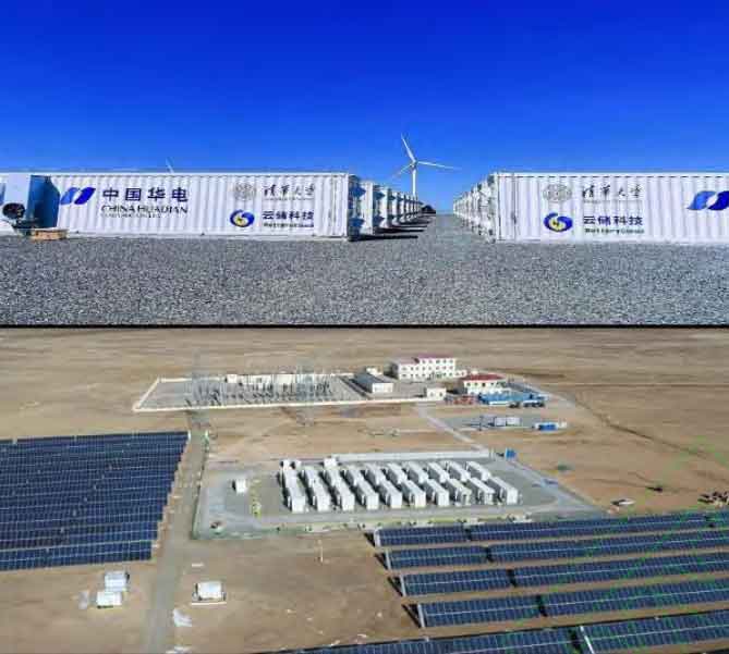
The performance of the dynamic reconfigurable battery energy storage system will be further validated based on the test and operation data of the 10 MW/34 MWh digital non-destructive cascade utilization energy storage demonstration project constructed based on DRB battery energy storage technology. The energy storage power station is located in Damao Banner, Inner Mongolia, and its site is shown in Figure 7.

4.1 Station Introduction
The 10 MW/34 MWh energy storage plant consists of 20 digital energy storage containers, each containing 4 digital energy storage subsystems. Each subsystem consists of battery units, digital energy exchange systems, and distributed PCS systems, with a DC side electrical specification of 716 V/480 Ah. Specifically, each subsystem is composed of 42 retired 51.2 V/200 Ah power battery modules connected in a topology of 3 parallel and 14 series. Each battery module is a lithium iron phosphate battery, consisting of 16 series connected 200 Ah battery cells with a specification of 3.2 V/206 Ah, a charging cutoff voltage of 3.65 V, and a discharge cutoff voltage of 2.0 V. The specific parameters of each component of the energy storage power station are shown in Table 2.
| Project | Rated voltage/V | Rated capacity/Ah | Rated power/kW | Rated power/kWh | Remarks |
| Single cell | 3.2 | 206 | 0.3296 | 0.6592 | Lithium iron phosphate monomer |
| Battery module | 51.2 | 206 | 5.2736 | 10.5472 | Cell 1 in parallel with 16 strings |
| Dynamic Reconfigurable Battery Network | 716.8 | 618 | 125 (Limited by PCS maximum power) | 442.9824 | Battery module 3 in parallel and 14 in series |
| Digital energy storage power station | 35k (AC) | 49440 | 10k | 34k | 80 sets of digital energy storage subsystems |
The digital energy exchange system includes four core devices, including a battery energy switch, a battery energy hub, a battery energy adapter, and a battery energy network card, which are used for system status detection and operation control, achieving battery module level charge and discharge balance, as well as online diagnosis and automatic isolation of suspected faulty battery modules, as shown in Figure 8.

4.2 Verification of SOC balance effect
In this example, the energy storage system operates in a fully charged and discharged condition. In this section, a charging and discharging cycle of a dynamic reconfigurable battery network of 3 parallel 14 strings is analyzed. The charging process first adopts 160 A constant current charging. When the battery voltage reaches the charging cutoff voltage, it switches to constant voltage charging. When the charging current decreases to 6.18 A (0.01 C), it is considered that the charging is terminated. The discharge process adopts a constant current discharge of 180 A, and the discharge is considered terminated when one battery cell reaches the discharge cut-off voltage. The ambient temperature for system operation is 12 ℃, and the cooling method used is air cooling.
Figure 6 shows the changes in module SOC during charging and discharging of a certain DRBN in the station. At the beginning of charging, the SOC of 42 battery modules showed significant differences, with a maximum value of 20% and a minimum value of 6%. After the charging process is completed, the maximum value of SOC becomes 99% and the minimum value is 93%. The variance of module SOC decreases from 15.12 to 2.77, and the range decreases from 14% to 6%. For the discharge process, the maximum and minimum SOC values at the beginning are 98% and 59%, respectively. After the discharge, the maximum and minimum SOC values are 8% and 3%, respectively. The SOC variance decreases from 96.34 to 2.0862, and the range decreases from 39% to 5%. These data indicate that both the charging and discharging processes, after consistency control by DRBN, the SOC differences of the battery module are reduced, which verifies the balancing ability of the DRB energy storage system.
4.3 Verification of integrated control performance for electric heating
DRBN can achieve integrated control of electric heating online, that is, achieve voltage balance while ensuring temperature stability. Figure 7 (a) shows the changes in module voltage of a certain DRBN during charging. At the beginning of charging, the maximum voltage of the module is 51.5 V and the minimum voltage is 48.3 V. After the charging process is completed, the maximum voltage is 54.0 V and the minimum voltage is 53.3 V. The variance of the module voltage decreases from 501 to 22.6, and the range decreases from 3.2 V to 0.7 V. This indicates that the module difference during the charging process is decreasing. In addition, Figure 7 (b) shows the temperature curve, and the accuracy of the temperature sensor is 1 ℃. As the charging process progresses, the variance of the module temperature decreases from the initial value of 0.4263 to 0.3362, and the maximum temperature difference remains stable. Although the overall temperature of the battery network shows an upward trend during the charging process, it is not difficult to see from the changes in the temperature curve that DRBN always maintains a good thermal equilibrium state.
Figure 8 shows the voltage and temperature curves during the discharge process. The maximum and minimum module voltages at the initial time are 52.9 V and 51.3 V, respectively. Due to the significant changes in the voltage characteristics of the battery at the termination time, the voltage data at a SOC of about 20% is taken for comparison. At this point, the maximum and minimum voltages are 50.7 V and 49.5 V, and the voltage variance decreases from 209 to 148, while the range decreases from 1.6 V to 1.2 V. In addition, the temperature curves of 42 modules showed a steady upward trend, with variances of 1.0113 and 1.0612 at the initial and end of discharge, respectively. This indicates that although the battery generates heat during the discharge process leading to an overall temperature increase in the system, the temperature difference between modules remains within a stable range, and there will be no thermal abuse of battery modules. Therefore, through the analysis of actual operating data of energy storage stations, the ability of dynamic reconfigurable battery energy storage system to integrate electric and thermal control has been verified.
4.4 Safety verification under fault conditions
In the working mode described in 4.2, the digital energy storage system collects data when a battery module fails. Figure 11 shows the entire process of isolating fault modules in a dynamically reconfigurable battery energy storage system. The battery energy storage system was originally operating in constant power discharge mode. At 492 seconds, a certain battery module malfunctioned, manifested as the open circuit voltage (OCV) of the module dropping from 52 V to about 20 V, significantly lower than the lower limit of the safe voltage range. At this point, the switch array immediately acts to remove the faulty module. At this point, the system is still in normal operation, and the output of the faulty module is borne by other healthy modules in the system. However, when the faulty module was removed, the module voltage self recovered. Therefore, after 48 seconds of removal, DESS attempted to connect the battery module. At this point, the module voltage drops again and oscillates continuously in the lower voltage range, indicating irreversible damage to the module and requiring maintenance and replacement. After the system stopped running, a multimeter was used to measure the port voltage of the faulty module as 9 V, confirming the fault condition of the module.

4.5 System Life and Economic Analysis
Dynamic reconfigurable systems can overcome the short board effect of battery networks and achieve balance between battery modules. Therefore, their reliability and system life are significantly improved compared to traditional battery systems. The evaluation of the lifespan of the energy storage system is based on the current health state of the entire system (system SOH), and the system reliability evaluation is based on the probability that the SOH of any battery module at the current time of the system is not less than a certain threshold. The decay of energy storage life and reliability changes under different strategy controls are given. The operating life of a fixed topology energy storage system is only 1929 days, and when the reliability threshold is 50% SOH, the reliability is 87.95%; Compared to traditional networks, the operating life of energy storage systems under dynamic reconfigurable topology is extended to 3614 days. When the reliability threshold is 30% SOH, the reliability is 95.82%. It can be seen that dynamic reconfigurable battery networks can effectively extend the service life and reliability of energy storage systems.
The economic analysis of dynamic reconfigurable battery energy storage systems can be carried out from two aspects: construction cost and full lifecycle cost. Regarding the construction cost, the cost of the dynamic reconfigurable battery energy storage system is basically the same as that of the traditional battery energy storage system. Firstly, at the battery body level, dynamically reconfigurable energy storage solutions can be compatible with different types and characteristics of battery modules, and have the ability to control the cascading utilization of retired batteries. There is no need to have strict requirements for the consistency of batteries at the factory, thus reducing the cost of battery selection; Secondly, at the level of battery management systems, for battery energy storage systems with similar control capabilities, dynamically reconfigurable energy storage solutions mainly achieve battery balance and energy control through secondary devices such as battery energy exchange systems, without the need for traditional battery balance circuits and power electronic converter modules. Compared to traditional solutions, dynamic reconfigurable battery energy storage systems have more obvious economic advantages in terms of full lifecycle costs. Firstly, in terms of system efficiency, dynamically reconfigurable solutions can overcome the short board effect, making more full use of battery capacity and power, thereby improving the overall operational efficiency of the system; Secondly, at the level of battery life, dynamically reconfigurable solutions can achieve module level balance, avoid conditions such as overcharging, discharging, and overheating that weaken battery life, thereby improving the cycle times and service life of the battery system, and reducing the average cost of energy storage system; Thirdly, at the level of system operation and maintenance, dynamically reconfigurable solutions can identify faulty modules and poorly performing modules in the battery network. Moreover, due to the system’s automatic fault isolation function, real-time operation and maintenance are not required, reducing the cost of operation and maintenance; Fourthly, at the system security level, dynamically reconfigurable solutions can achieve system level intrinsic safety, not only reducing the probability of faults occurring, but also accurately removing faulty battery modules, which reduces potential accident costs.
5. Further Discussion
In the current process of designing battery energy storage systems, there are a series of misconceptions that are worth exploring in depth. Firstly, there is the issue of ‘large and small’, which is the appropriate capacity of the battery cells used in the battery energy storage system. The advantages of large capacity battery cells are mainly concentrated in the relatively small number of battery energy control nodes, low difficulty in system integration, and low usage of battery pack components, reducing the difficulty of energy storage system integration and unit cost. However, currently, the large capacity battery cells on the market are composed of multiple 70 Ah or 140 Ah winding units assembled in a direct parallel mode using a common battery shell, which cannot fundamentally overcome safety issues such as circulating currents. To some extent, it will actually increase safety risks. In addition, due to the increase in cell volume and capacity, the heat dissipation performance of the cell itself is poor, which increases the difficulty of electric heating safety control in system integration. At present, large capacity battery cells are mainly used in the field of power energy storage. Although the cost reduction of large capacity battery cells can directly lead to a reduction in initial investment costs, it cannot be inferred that the full life cycle cost reduction of battery energy storage systems can be achieved. Compared to pursuing high capacity of battery cells, the battery energy storage system architecture based on dynamic reconfigurable battery networks can be compatible with multiple capacity specifications of battery cells, and has advantages in improving the capacity utilization rate and system cycle life of the entire life cycle of the energy storage system.
Secondly, there is the issue of “high and low”, which is how large the DC side voltage level needs to be selected for the battery energy storage system. Based on the current “string only, not parallel” grouping method, improving the cluster level power density of batteries can only be achieved through the use of large capacity cells and high-level cluster level voltage. At present, typical high-voltage systems are battery energy storage systems with higher voltage levels such as single string 1500 V or cascaded/high-voltage direct mounted, which have the advantage of simplifying station design and reducing grid connection costs. However, applying low voltage battery monomers of around 3 V to a high potential working environment, high electromagnetic fields can have an impact on the electrochemical reactions inside the battery, causing the aging mechanism and safety boundary of the battery to deviate significantly from the results of battery type tests, posing a huge challenge to the safety and reliability of the battery energy storage system. In the power system, the design of a battery energy storage system should not only consider the voltage output of the system, but also consider the electrochemical reaction characteristics of the battery. From the perspective of the intrinsic safety of the battery system, the optimal design of the battery energy storage system can be given. Compared to the approach of pursuing the use of large capacity cells and increasing the cluster level voltage level to enhance the power density of battery clusters, the battery energy storage system architecture based on dynamic reconfigurable battery networks achieves high power density of the battery energy storage system at 1000 V voltage level through controllable parallel connection, greatly improving the intrinsic safety of the system and the operation and maintenance under safe voltage.
The third issue is the issue of “new versus old”, which is how to accurately evaluate the status of a battery unit. As an electrochemical reaction device, batteries are influenced by various working conditions such as charge discharge rate, environmental temperature, and cycle times. The nonlinearity, uncertainty, and aging during their storage and use are inevitable, which are completely different from the factory consistency of batteries. In addition, the current battery life assessment usually uses the cycle life obtained from accelerated aging testing at the factory. As a new type of energy infrastructure, battery energy storage systems need to operate for up to 20 years and face multiple dynamic operating conditions during this period. Therefore, factory consistency and cycle life are used to calculate the usage effect, system safety boundary, and Economic and reliability indicators are unreasonable and impossible. In addition, as more and more power batteries are retired from electric vehicles, the green and efficient utilization of a large number of retired power batteries in the future is also a major issue related to the closed-loop of the electric vehicle industry chain and value chain. The architecture of a battery energy storage system based on dynamic reconfigurable battery networks achieves precise online state estimation, operational potential evaluation, and capacity measurement of battery units through spatiotemporal fine-grained perception and control, similar to the use process of computer hard drives, which is both a detection process and a measurement process. In addition, the battery energy storage system based on dynamic reconfigurable battery networks can effectively shield the physical and chemical differences of battery bodies, achieving seamless connection between retired power batteries on and off the vehicle, greatly improving the safety and economy of retired power battery energy storage systems, and strongly supporting a new model of green and efficient utilization of battery assets for the entire life cycle.
6. Conclusion
A dynamic reconfigurable battery energy storage technology is proposed to address the “short board effect” of traditional battery energy storage systems, in order to improve the safety and energy efficiency of battery energy storage systems. The main contributions include the following aspects:
(1) Analyzed the principle and architecture of a dynamically reconfigurable battery energy storage system, DRBN changed the connection mode of the battery network from traditional fixed series parallel rigid connection to program controlled flexible connection, creatively opening up a path to achieve energy management and control of the battery network from a time dimension.
(2) A method for energy control and system level intrinsic safety control based on dynamic reconfigurable battery energy storage technology has been proposed. Energy control is optimized with the goal of system energy efficiency, and system level intrinsic safety control improves safety from the perspective of controllable series parallel connection.
(3) A large amount of actual operation data has verified that the dynamic reconfigurable battery energy storage technology has the ability to balance SOC and integrate electric and thermal control. The maximum SOC difference during the charging and discharging process is controlled within 5%, and the maximum temperature difference of the module is controlled within 5 ℃; In addition, the operational data before and after the fault indicates that dynamic reconfigurable battery energy storage technology can timely cut off faulty battery units, ensuring the safe and reliable operation of the system.