
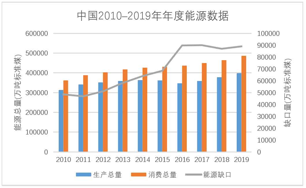
National development and people’s lives cannot be separated from energy. Especially in today’s society promoting the construction of smart cities, the importance of energy is self-evident. From 2010 to 2019, China’s annual total energy production and consumption have been increasing year by year. With the rapid development of the country, energy demand is also gradually increasing.
As shown in the figure, China’s energy supply capacity cannot fully meet the current social development needs. In recent years, the energy gap has gradually increased, and how to improve energy utilization efficiency has become an important research direction in the current energy field. There are various forms of energy, including one-time energy such as coal and oil, as well as renewable energy such as solar and wind energy. In real life, power stations convert the above types of energy into electricity and transmit it through distribution networks to meet the electricity needs of household life and enterprise production.
Due to social habits, there is always a certain pattern of changes in the state of the power grid, manifested in the concentration of electricity demand in the distribution network during the active period of users, during which the current on the distribution network lines will maintain a high level for a long time. Due to excessive load during the day, the quality of the power grid has significantly decreased; At night, due to a significant reduction in electricity demand, the generator idles and the energy utilization rate is low. This uneven distribution of electricity demand can bring many hazards. In terms of motors, when the motor is under load, a current passes through the stator coil, generating an armature magnetic field, causing the armature effect. The motor generates electromagnetic torque with braking properties, causing a decrease in motor speed and a change in grid frequency. The degree of frequency deviation of the grid is positively correlated with the current passing through the stator coil, which can lead to abnormal equipment operation in severe cases; On the user side, the greater the current passing through the distribution network, the more severe the line loss, and there will be significant voltage drop in the power grid. Under heavy load conditions, the fluctuation amplitude can even reach 20%, leading to equipment working in an undervoltage state and increasing losses. In severe cases, it will trigger equipment power outage protection, causing great inconvenience to residents’ lives and industrial production.
In response to this uneven distribution of electricity demand, the country has proposed a policy of peak and valley electricity, which alleviates the pressure on power stations and improves the quality of the distribution network by transferring electricity demand from the user side. The implementation of peak and valley electricity policies has indeed improved this phenomenon, but the imbalanced characteristics of electricity demand in the time dimension have not changed, and the problem has not been substantially resolved.
In recent years, relying on the development of technology and processes in the energy storage industry, the service life of energy storage equipment has been continuously increasing, the operational reliability has been gradually improved, the power and capacity have been gradually scaled up, and the investment cost has also decreased, providing new ideas for solving these problems. Meanwhile, after years of technological optimization and innovation, batteries have been widely used in daily life, laying the foundation for the rise of Distributed Battery Energy Storage System (DBESS).
The distributed battery energy storage system obtains and stores electrical energy through energy storage batteries during low load in the power grid, improving the energy utilization rate of the power grid; Release electrical energy during high loads, assist user equipment in power supply, reduce regional dependence on the distribution network, and improve the quality of the power grid. At the same time, new energy technologies such as photovoltaic panels and wind turbines are gradually maturing, and distributed battery energy storage systems can store clean energy such as wind and solar energy for secondary utilization, solving the problem of insufficient electricity during peak hours. With the development and maturity of battery energy storage technology and strong support from national policies, distributed battery energy storage systems have good prospects, and studying their applications is a very meaningful topic.
1. Current status of battery research
According to the different principles of energy storage, the mainstream batteries on the market can be divided into lead-acid batteries, lithium batteries, sodium sulfur batteries, and other batteries. Lead acid batteries were first proposed in 1860, consisting of PbO2 as the positive electrode, sponge like Pb as the negative electrode, and sulfuric acid aqueous solution as the electrolyte. They are safe, reliable, and the most mature in technology; Lithium batteries achieve chemical energy storage and release through the transfer of positive and negative electrode plates of lithium-ion Li+. In 1992, Sony Corporation of Japan took the lead in developing and successfully developing lithium batteries. Lithium batteries are widely used in the field of mobile devices due to their high energy ratio and long lifespan; Sodium sulfur batteries use liquid sulfur and molten sodium polysulfide as positive electrodes, molten metal sodium as negative electrodes, and electrolytes as β– A high-energy secondary battery composed of Al2O3 and S2 to form sodium polysulfide products. In 1983, NGK Corporation of Japan completed the construction of an energy storage station based on sodium sulfur batteries and put it into commercial operation; Other batteries mainly include liquid flow batteries, supercapacitors, etc. Liquid flow batteries achieve energy storage and release through reversible redox reactions between positive and negative electrolyte solutions. Supercapacitors, similar to traditional capacitors, can achieve fast response energy storage through the Coulombic force between the interface bilayers, and have good application prospects in the field of distribution network regulation.
| Battery type | Specific power/(W/kg) | Specific energy (Wh/kg) | Efficiency/% | Lifetime/h | Power Cost/($/MW) |
| Lead-acid battery | 75-300 | 30-50 | 70-90 | 100-5000 | 0.30-0.60 |
| Liquid flow battery | 15-60 | 50-120 | 70-80 | >10000 | 3.0-3.7 |
| Sodium sulfur battery | 90 – 230 | 150 – 240 | 80 – 90 | 2000 – 4500 | 3.10 – 4.00 |
| Lithium battery | 150-315 | 150-200 | 85-95 | 5000 | 1.09-4.10 |
Batteries that achieve energy storage through the mutual conversion between electrical and chemical energy are collectively referred to as electrochemical batteries. Lead acid batteries, lithium batteries, sodium sulfur batteries, and flow batteries are all electrochemical batteries, and their comparison is shown in Table 1. Electrochemical batteries have a relatively simple structure, high safety factor, and convenient maintenance, making them widely used in mobile devices such as mobile phones, power banks, and handheld terminals. In recent years, due to the gradual maturity of battery design and manufacturing processes, the energy density and power of batteries have significantly increased, and the cost of unit energy storage has been reduced. They have been widely used in the field of high-power energy storage.
2. Current research status of battery charging and discharging technology
The technology of battery charging and discharging is essentially a different research direction for switching power supplies. 220V AC power is supplied through a switching power supply to output low-voltage direct current, and multi-stage charging of the battery is achieved through constant current or constant voltage control; The low-voltage direct current of the battery is converted into a 220V sinusoidal power output similar to the mains power through a switching power supply.
Switching power supply technology can be divided into non isolated and isolated power supplies based on whether there is a direct electrical connection between the input and output. The non isolated switching power supply is proposed to address the efficiency issue of traditional linear power supplies. Its core is to achieve level conversion through inductor or capacitor energy storage. It can be divided into BUCK, BOOST, BUCK BOOST, and Cuk type converters based on circuit structure and function. The comparison is shown in Table 2.
| Topological structure | Principle | Characteristics |
| BUCK | The switch tube and inductor are connected in series to the circuit. By switching the state of the switch transistor, the energy storage or release of the inductor is achieved. At different stages, the load is powered by the power supply and the inductor, and the output voltage can be controlled by adjusting the duty cycle of the switch transistor. | Step-down converter, inductive energy storage, with an output voltage value smaller than the input voltage and the same polarity. |
| BOOST | Inductors are connected in series and switch tubes are connected in parallel to the circuit. When the switch tube is conducting, the current on the inductor surges; When turned off, the inductance current cannot suddenly change, so an induced voltage much greater than the input voltage will be generated at both ends of the inductance. | Boost converter, inductive energy storage, with an output voltage greater than the input voltage and the same polarity. |
| BUCK – BOOST | The switch tubes are connected in series and the inductors are connected in parallel to the circuit. When the switch tube is conducting, the current on the inductor surges; When turned off, similarly, an induced voltage is generated at both ends of the inductor, with polarity opposite to the input signal. | The output voltage of an up/down converter with inductive energy storage can be greater than or less than the input voltage, with opposite polarity. |
| Cuk | The input and output terminals each have inductors and are connected through capacitors. When the switch is on, the output inductance and capacitance form a circuit; When turned off, the input inductance and capacitance form a loop. | Relying on capacitor energy storage to achieve voltage rise and drop, the output voltage polarity is opposite. The inductance at the input and output terminals reduces the current ripple. |
However, due to issues such as susceptibility to interference and poor safety, non isolated switching power supplies cannot be popularized in specific fields, so isolated power supply designs have been proposed. The isolated switching power supply can be divided into flyback, forward, push-pull, half bridge, and full bridge converters based on the circuit structure. The comparison is shown in Table 3.
| Topological structure | Principle | Characteristics |
| Flyback | A single switch tube controls the primary side on/off of the transformer, and the secondary output end is the transformer’s synonym end. Based on the electromagnetic effect of transformers, an induced voltage is generated on the secondary side through alternating conduction of switch tubes to supply power to the load. | The structure is simple, the primary side of the transformer requires an RC absorption circuit, and the switch tube requires a high voltage withstand value, magnetic core, and low energy utilization rate. It is usually used in the design of low-power switching power supplies. |
| Forward excitation | The secondary output end is the same name end of the transformer. When the switch tube is turned on, an induced voltage is generated on the secondary side of the transformer, and the load is supplied by the transformer; When turned off, the load is powered by capacitors. | It is prone to magnetic saturation and is usually equipped with a magnetic flux reset circuit. |
| Push pull | The primary side of the transformer is a symmetrical structure, and the control signal is two square wave signals with a phase difference of 180 °. Energy transmission is achieved through alternating conduction of switch tubes. | Simple structure and high utilization of magnetic cores. The transformer has multiple primary windings, and the withstand voltage value of the switch tube should not be lower than the input voltage and the induced voltage of the transformer primary side. |
| Half bridge type | The bridge structure is composed of two switch tubes and two voltage divider capacitors. The control signal is two square wave signals with a phase difference of 180 °, and energy transmission is achieved through alternating conduction of the upper and lower bridge arms. | The voltage borne by the primary coil is 1/2 of the push-pull topology, and the device requires a low voltage withstand value. But at the same power, the primary side of the transformer requires twice the current, and the switch tube loss is high, so it is usually used in the design of medium power switching power supplies. |
| Full bridge type | The bridge structure is composed of four switch tubes, and switch tubes with different bridge arms are controlled by the same signal, and the working principle is similar to a half bridge topology. | The circuit is complex and costly, and is usually used in the design of high-power switching power supplies. |
In 1955, American engineer Roger introduced a transistor based self-excited oscillation DC converter, and pulse width modulation technology was first proposed, becoming the theoretical foundation of switching power supplies; In 1964, American engineers first proposed a switch mode power supply scheme without a power frequency transformer; From 1970 to 1990, with the introduction of power switch transistors such as power transistor GTR, insulated gate bipolar transistor IGBT, and metal oxide semiconductor field-effect transistor MOS, switching power supplies entered the era of high-frequency and high-power; In the 1990s, in response to the switching losses of high-frequency switching power supplies, high-frequency switching power supplies using soft switching technology emerged; In the late 1990s, in order to solve the problem of current waveform distortion caused by different phases of voltage and current in switching power supplies, Power Factor Correction (PFC) technology was proposed, which improved power efficiency and reduced electromagnetic interference.
In terms of AC-DC switching power supply, in 2002, Yan et al. first proposed a technical solution to achieve LLC soft switching through MOS parasitic capacitors; In 2007, Xie Wentao and others implemented a low-power half bridge LLC resonant converter; In 2011, Dong Yan, Wang Yingqiang, and others conducted modeling on a resonant cavity to study the effects of resonant parameters, devices, and other factors, and optimized the design of a half bridge LLC resonant circuit; In 2018, Hu Yong, Gao Wengen, and others studied the current sharing control strategy for parallel output of switching power supplies.
In terms of DC-AC switching power supply, inverters can be divided into high-frequency transformers and power frequency transformers based on their operating frequency. The technology of power frequency transformers is mature, and electromagnetic interference is relatively small. However, the equipment is large and cannot adapt to the trend of contemporary miniaturized power supply. In the 1960s, the emergence of a semi controlled thyristor SCR replaced the traditional DC motor AC generator inverter method; With the introduction of sine pulse width modulation technology, equivalent voltage output is achieved by controlling the duty cycle of the switch, resulting in less harmonic output voltage and simple circuit design. Afterwards, various inverter circuit topologies based on SPWM technology emerged, and the load capacity and power density of the inverter continued to improve, but at the same time, it also brought about electromagnetic interference problems.
Summarize
Research on a battery energy storage system based on lead-acid batteries, which includes charging circuit, inverter circuit, and control circuit
The road and lead-acid battery are divided into four parts. The charging and discharging circuit of lead-acid batteries realizes bidirectional energy exchange between the distribution network and the batteries. By cycling the charging and discharging modes in different periods, the surplus and low-priced electricity from the distribution network during the valley period is stored in lead-acid batteries; During peak electricity usage, the energy of lead-acid batteries is released and used for household equipment power supply, achieving secondary utilization of peak and valley electricity and reducing household electricity costs. The front stage of the charging circuit adopts a parallel interleaved BOOST type APFC circuit, which uses PFC technology to achieve input voltage and current in phase, improve energy utilization, and reduce input current ripple through parallel interleaving, reducing device voltage and current stress. Finally, the bus DC voltage is raised to 420V; The rear stage adopts a half bridge LLC resonant circuit, which uses a resonant cavity composed of MOS parasitic capacitors, resonant inductors, excitation inductors, and resonant capacitors to achieve MOS zero voltage switch (ZVS) and rectifier diode zero current switch (ZCS) technology, reducing circuit switch losses and outputting 48-58V low-voltage DC power. By adjusting the operating frequency, constant voltage or current output is achieved, Realize multi-stage charging of lead-acid batteries. The front stage of the discharge circuit adopts a series push pull boost circuit to boost the 44-54V low-voltage direct current of the lead-acid battery to 400V, and the series connection of the transformer reduces the voltage stress borne by the transformer; The 400V high voltage on the bus voltage is modulated by a full bridge inverter circuit SPWM waveform, and filtered to output pure 220/50Hz sinusoidal electricity.
The control circuit uses STM32F407ZGT6 as the main control chip, adjusts the working mode by setting the relay group status, and achieves isolated battery voltage and current data collection and upload on the UCOSIII real-time operating system, as well as system information display and control on the touch screen.
A brief analysis of the current research status of battery technology and related charging and discharging technologies at home and abroad, the design analysis of battery energy storage systems, the overall design of the system, and the introduction and principle analysis of the charging and discharging circuits, including the staggered parallel BOOST boost circuit and half bridge LLC resonant circuit of the charging circuit, the push pull boost circuit of the discharge circuit, and the full bridge SPWM inverter circuit.
The main circuit design of the battery energy storage system elaborates on the parameter calculation and device selection of important components in the charging and discharging circuits. Control design of battery energy storage system, explaining the hardware and software design of the system control part. The hardware includes isolated voltage, current collection, communication, and relay group control circuits, and the software includes single board program and upper computer program design. The battery energy storage system was tested and analyzed, and independent performance tests were conducted on the charging and discharging circuits, which were verified through the overall functionality of the system.