
Energy and environmental protection issues are increasingly receiving attention from people from all walks of life at home and abroad. In recent decades, the harmfulness and limitations of traditional energy have had a significant impact on the natural environment and fossil fuels. Countries have had to accelerate the promotion of new energy, and correspondingly, the development and utilization of new energy has become a priority for various countries.
Energy storage power technology, as the core support for the development of new energy, its innovation and breakthrough will become an important leading technology driving revolutionary and disruptive adjustments to the global energy landscape. As a carrier of energy storage power technology, lithium-ion batteries have the advantages of high working voltage, high specific energy, long cycle life, and high environmental friendliness, making them widely used in rechargeable energy storage battery. However, in a long chain energy storage power supply system, the voltage and capacity of a single battery are far from sufficient. In practical applications, a series parallel connection is often used to combine multiple batteries to form a suitable voltage level long chain power supply group. Due to inevitable manufacturing differences and the influence of different internal and external factors such as self discharge rate, aging degree, working state, and working environment during the charging and discharging process of batteries, the differences in these changes will become increasingly significant with the increase of usage times. The use of battery packs in series is affected by the inconsistency between batteries, which easily leads to overcharging and discharging, greatly reducing battery performance. How to solve the “short board effect” of battery capacity has become a bottleneck that restricts the safe and reliable operation of battery packs.
The introduction of balancing technology can greatly improve the performance of energy storage battery packs and enhance their system security. However, the existing balancing technology still faces problems such as slow balancing speed, low balancing efficiency, and single balancing method when applied to long chain series battery packs. To address these issues, this paper proposes a distributed balancing charging system structure, This structure can be seen as a two-layer distributed balanced charging system consisting of multiple parallel input series output balanced charging modules. By inputting a DC bus, the charging and discharging cross group balancing of the energy storage battery pack can be achieved, as well as the local self balancing function of the energy storage battery pack. The speed of cross group balancing is much faster than that of local self balancing, which can quickly complete the balancing between battery packs at any position in the long chain battery pack. At the same time, with appropriate balancing control strategies, the dynamic charging, discharging, and balancing effects of long chain battery packs can be more efficiently achieved. It can also make the charging module fully match the voltage level of the energy storage battery, with advantages such as high modularity, high scalability, and strong parallel balancing ability. Considering that each lower level unit circuit needs to be equipped with a bidirectional charging module, its cost will increase with the increase of the number of energy storage battery cells. Therefore, it is particularly important to determine the topology of the lower level units and develop a coordinated charging balance working mode. Therefore, studying the distributed balanced charging system and control strategy of series energy storage sources is of great practical significance.
1. Current research status and analysis at home and abroad
The distributed balanced charging structure adds balancing function on the basis of distributed charging. Therefore, the distributed balanced charging system of series energy storage power sources mainly includes three aspects: lower level unit balancing topology, distributed charging system structure, and balancing control strategy. The following will introduce these three aspects separately.
1.1 Lower level unit balanced topology
Energy storage battery balancing technology is widely used domestically and internationally in driving new energy vehicles, electric buses, and drones that require high energy storage battery voltage. It has a significant promoting effect on solving the problems of low available capacity and reduced cycle life of lithium-ion battery packs caused by the inconsistency of long chain battery cells. Therefore, domestic and foreign scholars have done a lot of work on the research of this technology, and to a certain extent, a complete structural system has already been established. Its working principle is mainly to use a balancing circuit to charge and discharge individual imbalanced cells, ensuring that the state of charge of the imbalanced cells remains consistent, thereby achieving the purpose of energy transfer, compensating for the differences caused by the inconsistency of energy storage battery, and improving the performance of energy storage battery packs.
At present, the balancing topology of energy storage battery is mainly divided into passive balancing and active balancing according to the different forms of energy transformation. Compared to the two, passive equalization circuits were the earliest used equalization circuits and have been widely used in low-power circuits due to their simple structure and control. The structure of an active balancing circuit is more complex than that of a passive balancing circuit, and it also requires corresponding balancing strategies to achieve good balancing effects. However, this circuit does not achieve balancing in the form of energy consumption, but rather achieves balancing through energy transfer between batteries, with higher efficiency and faster balancing speed. It can be applied in high-power circuits.
1.1.1 Passive Balanced Topology
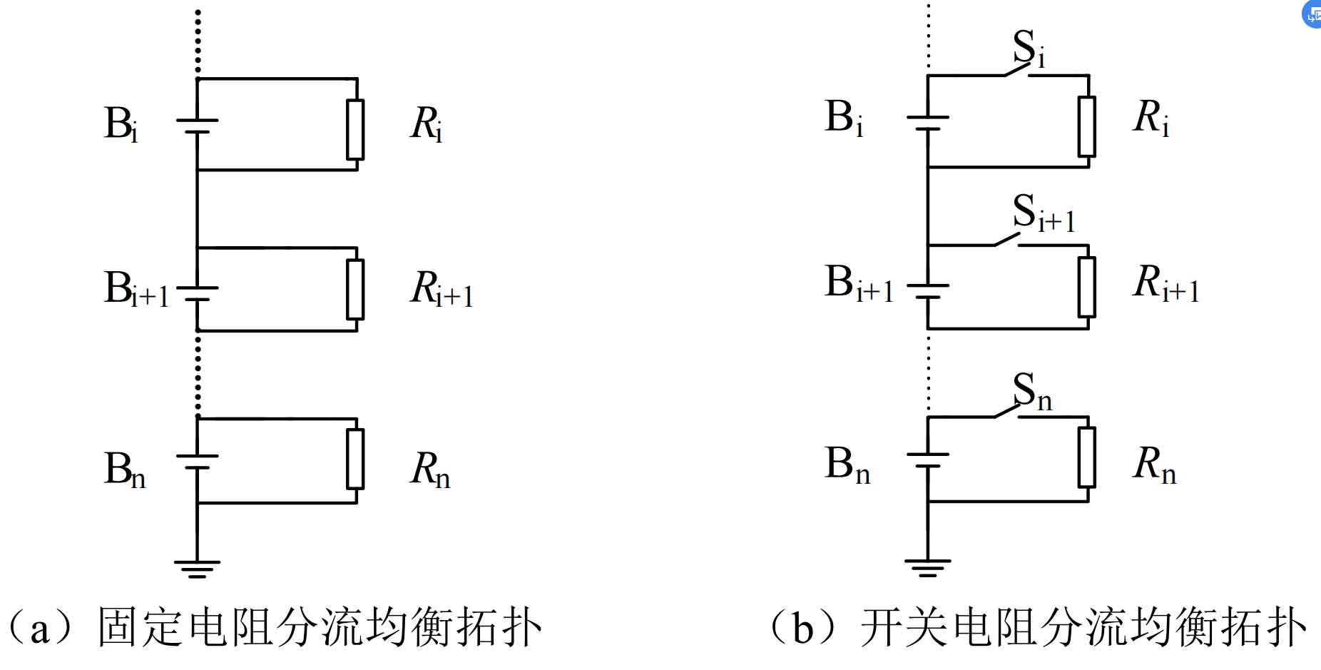
The passive balancing topology belongs to the passive balancing circuit, which uses heat dissipation to level the higher energy storage battery with the lowest energy storage battery, achieving consistency among the individual units of the energy storage battery pack. The shunt resistor balance structure is more widely used in practice, and can be divided into fixed resistor shunt balance topology and switch resistor shunt balance topology. The fixed resistance shunt balance topology is shown in Figure 1 (a). Each energy storage battery is connected in parallel with a resistor through wires to achieve the purpose of shunt. This circuit has a simple structure, low cost, and strong reliability. However, due to the limitation of releasing a large amount of heat during charging and discharging, it can only be used in low-power situations. The switch resistor shunt balance topology is shown in Figure 1 (b). On the basis of a fixed resistor shunt balance topology, a switch element is connected in series between the energy storage battery cell and the resistor to selectively discharge the high charge energy storage battery. During the charging process of the energy storage battery, the blocking of the switch does not allow each resistor to merge into the circuit, reducing energy loss, Therefore, this circuit structure is more efficient and reliable than a fixed resistor shunt balanced topology.
1.1.2 Active balancing topology
Active balancing topology, also known as active balancing circuit, is proposed based on the limitations of passive balancing topology. Active balancing circuits use power electronics technology to balance the energy of high-energy and low-energy energy storage battery, unlike passive balancing topologies that consume excess energy in high-energy storage battery. However, the process of balancing energy requires an intermediate energy storage element as a relay, such as an inductor, capacitor, or transformer. From this, it can be seen that the main losses of active balancing topology are only the losses of intermediate energy storage components and the switching losses of switching tubes. Therefore, the balancing current can be designed to be large, and the balancing efficiency and speed can be greatly improved. It is widely used in high-power applications.
In recent years, more and more scholars have conducted research on active balancing topologies. Active balancing topologies can be divided into four types based on the medium of energy propagation: capacitive, single inductor, multi inductor, and coupled inductor; According to the propagation path of energy, it can be divided into direct equilibrium type and non direct equilibrium type. The following introduction will be conducted from the perspective of energy propagation path.
(1) Indirect equilibrium
Non direct balanced topology refers to the inability to directly transfer energy between any two individual cells or groups within a long chain battery pack. Based on this characteristic, the following introduces three typical inductor balanced topologies, taking individual cells, individual cells, and group groups as examples.
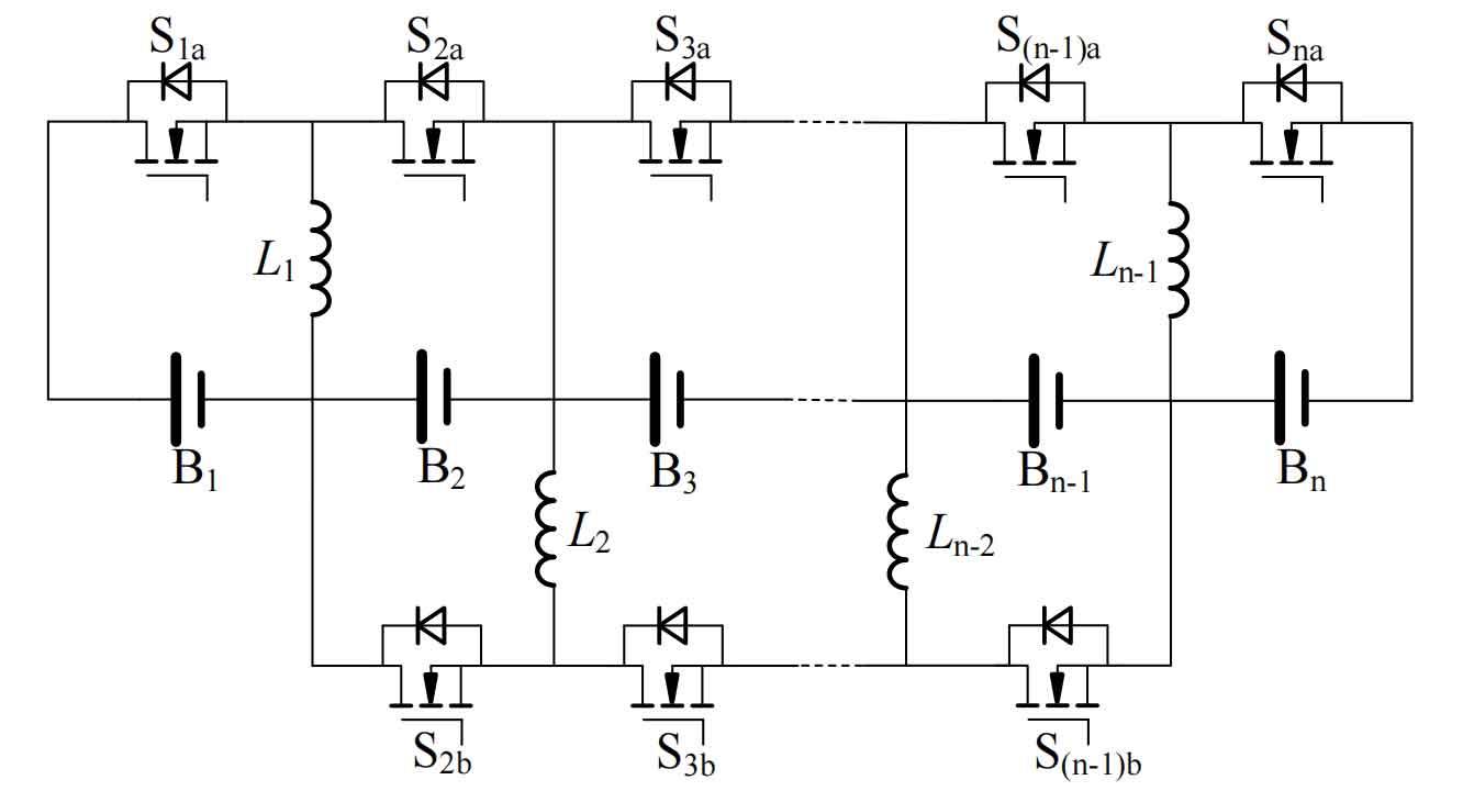
The figure 2 shows a traditional inductive equalization circuit, which is an adjacent single to single direct equalization circuit. Each inductor that stores energy corresponds to an energy storage battery cell and two MOS transistors. When two adjacent energy storage battery are imbalanced, the buck boost mode energy transfer can be achieved by controlling the on/off of MOSFETs. Multiple adjacent energy storage battery can work in parallel simultaneously, which is beneficial for improving the balancing speed. However, when there are non adjacent imbalanced energy storage battery, energy transfer in one cycle needs to be completed through multiple balancing actions. The balancing efficiency decreases geometrically with the number of balancing steps, especially when balancing at the beginning and end of a long chain battery pack, the efficiency is the lowest and the balancing time is the longest. Therefore, this circuit topology has significant limitations in terms of balancing performance.
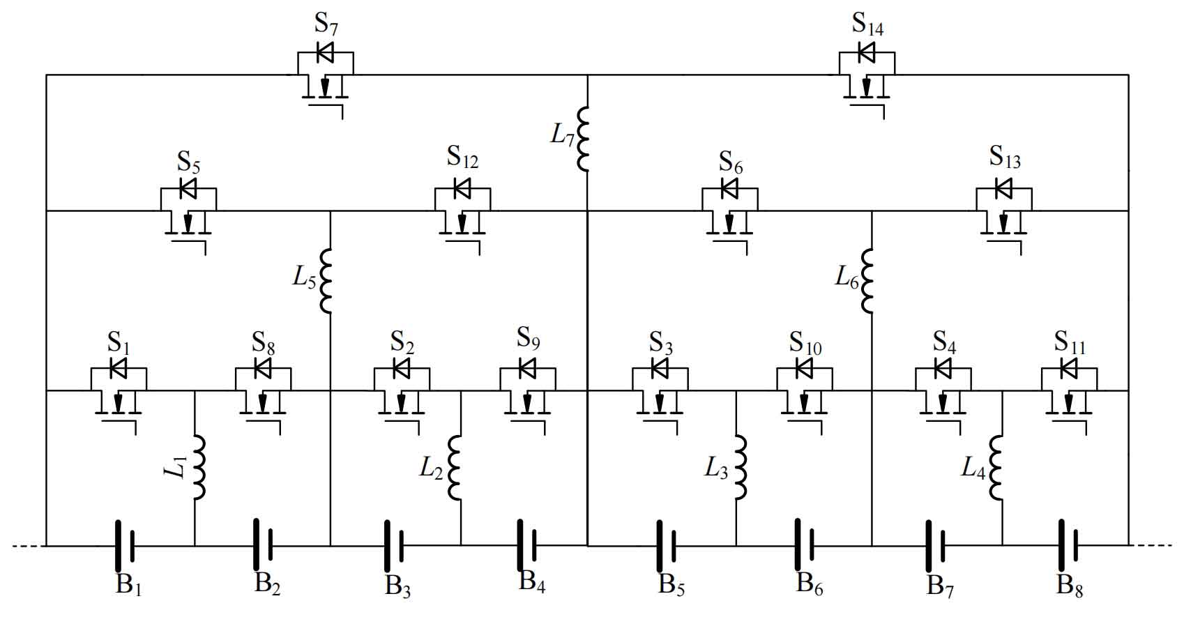
Improvements have been made to this, as shown in the figure 3, which is an improved inductive buck boost balancing circuit. This circuit overcomes the problem of energy transfer from traditional buck boost balancing circuits to individual units, and adds direct balancing paths for some pairs of groups, making the balancing speed of intermediate units as fast as that of head and tail units. However, the balancing mode of this structure is still not flexible enough, Still unable to achieve direct balancing of any individual cell within the energy storage battery pack.
The coupled inductance balanced topology is a balanced circuit with a coupled transformer as the intermediate energy storage element. It generally transfers energy by operating the circuit in flyback mode. There are many types of coupled transformers, including one-to-one coupling, one to many coupling, and many to many coupling. The balancing current of the coupled inductor type balancing circuit is relatively large, so the balancing speed is fast, and energy is transmitted through magnetic isolation, which can transfer energy over long distances, reduce energy loss caused by multi-step balancing, and improve balancing efficiency. However, due to the relatively large volume of coupling transformers, especially in one to many coupled and many to many coupled transformer structures, there may be difficulties in designing coupling transformers due to the large number of coil turns and small magnetic core window area, as well as high PCB layout requirements, which are not easy to expand.
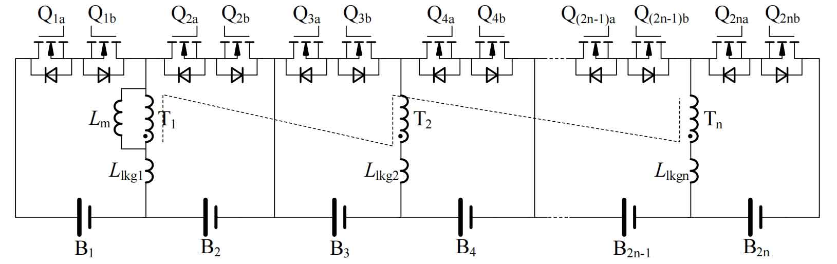
Figure 4 shows a bidirectional coupling balanced circuit [32], in which each energy storage battery cell is equipped with a one-to-one coupling transformer and two MOS transistors, which can enable bidirectional energy transfer between the energy storage battery pack and the cell. However, this circuit has a serious balancing overlap phenomenon, which can lead to high losses, long balancing time, and other problems, and cannot directly balance the individual or group within the energy storage battery pack, As the number of energy storage battery increases, the number of transformers also increases, greatly affecting the scalability of the system and making it unsuitable for long chain battery packs.
The hybrid balanced topology includes both inductor and coupling inductor as intermediate energy storage components. By combining the inductor and coupling inductor, the changes in the circuit structure can be more diverse, optimizing the balanced path to a certain extent and increasing more possibilities.
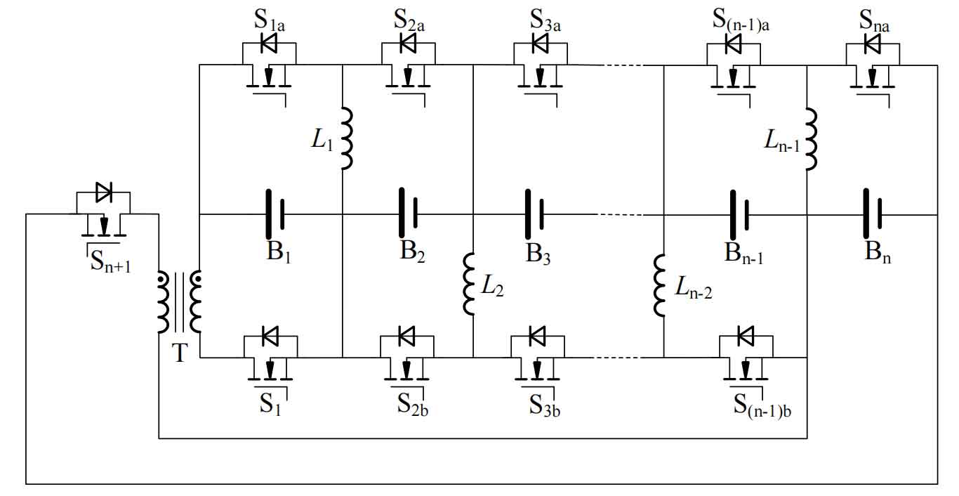
Figure 5 shows a hybrid single to single improved equalization circuit, which adds a one-to-one coupling transformer and two MOS transistors to the traditional inductive buck boost equalization circuit structure. The first and last two batteries of the energy storage battery pack can be directly balanced through transformers and MOSFETs S1 and Sn+1, optimizing the balancing problem of the longest path in traditional inductive buck boost balancing circuits. However, the problem of multi-step balancing for non longest balancing paths is still unresolved, and it is also impossible to achieve direct balancing function for any individual or group of long chain battery packs, with few balancing paths and low balancing flexibility.
(2) Direct balanced topology
Non direct balancing topology often requires multiple transformations in the balancing path of non adjacent battery cells in a long chain battery pack to achieve energy transfer. However, direct balancing topology circuits use their clever circuit structure to construct more direct balancing paths, significantly improving the drawbacks of low balancing efficiency and long balancing time caused by long balancing paths.
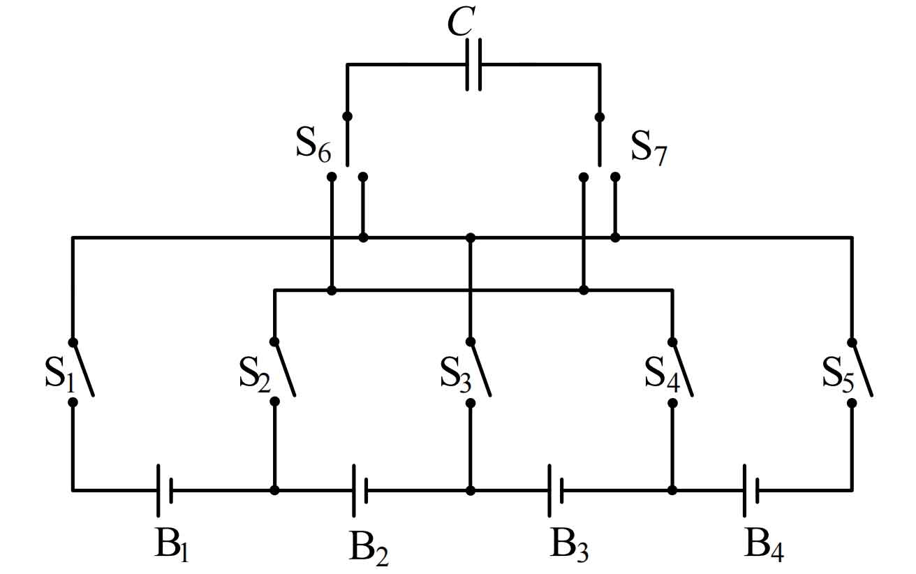
Figure 6 shows a single switched capacitor direct equalization circuit. This circuit only requires an intermediate energy storage capacitor. By controlling the bipolar switches at both ends of the capacitor and the switching tubes at both ends of the energy storage battery, a circuit is formed between the rich energy battery and the capacitor. After the capacitor stores energy, the switch direction is changed to form a circuit between the fully charged capacitor and the energy storage battery, thereby achieving energy transfer. This method can achieve direct balancing between any unbalanced units, and the circuit structure is also simple. However, the existing problems are also obvious. The switch capacitor balancing circuit needs to determine whether the voltage difference between energy storage battery cells is greater than a certain threshold in order to better transfer energy. The balancing effect is not thorough, and the capacitor has a large instantaneous peak current at the moment of switching, which is easy to cause damage to the energy storage battery.
The direct balancing circuit of the flyover inductor is proposed by Korean scholars, as shown in Figures 7. This circuit only requires one flyover inductor to achieve multi-path energy transfer. Each energy storage battery cell is equipped with two sets of diodes and MOS tubes connected in series on one side. In addition to the battery side sharing a set of switching tubes at the beginning and end of the energy storage battery pack, both are used to control the energy transfer path, which can achieve any single cell to single cell, single cell to group The direct balancing between groups has a short balancing path and flexible unit expansion. However, for low voltage cells, the voltage drop loss of diodes is severe, and there is a problem with the freewheeling path during the blocking time of inductor switching switching switching.
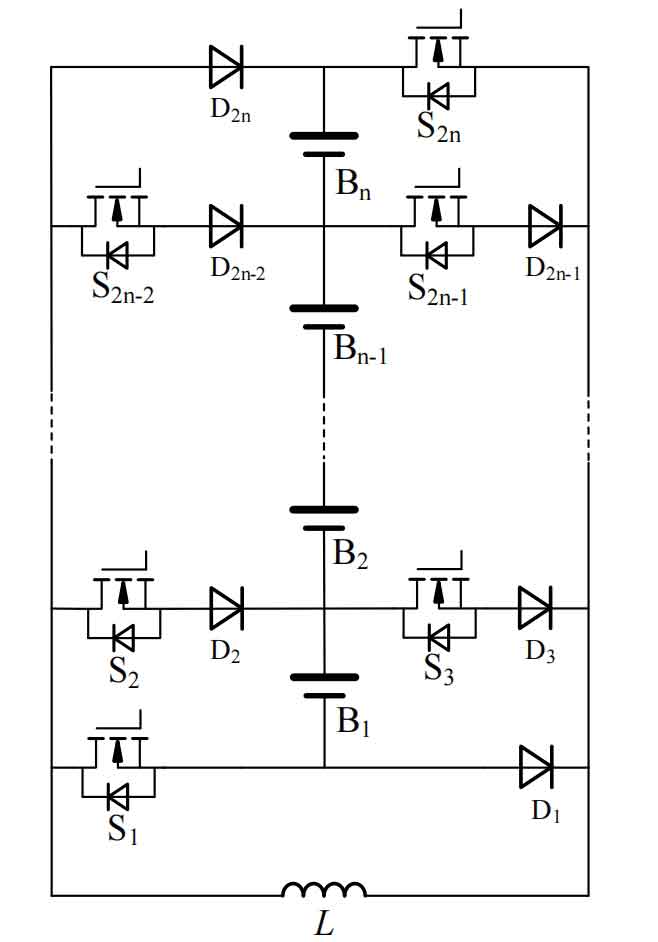
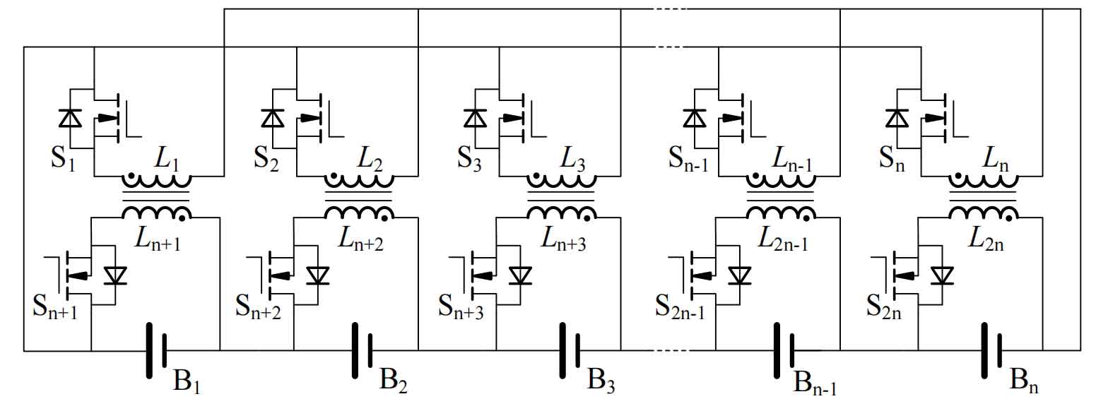
The fully coupled direct balancing circuit is shown in the figure 8. Each energy storage battery cell in the circuit has a set of bidirectional switches, and there is a coupling inductance between the cell numbers 2n-1 and 2n (n=1,2…), which can perform bidirectional Buck Boost mode balancing on two adjacent cells of the same winding. For non adjacent cells, flyback transformation mode can be used, but direct balancing between odd and even can only be performed according to the cell number, Otherwise, an additional step of direct equilibrium between adjacent monomers is required. Compared to the direct balancing circuit with flying inductors, the number of switching tubes is reduced, and the direct balancing path between individual cells is shorter, improving the balancing efficiency. However, it cannot achieve direct balancing between groups and lacks flexibility.
1.2 Distributed Charging System Architecture
In recent years, distributed charging systems have been applied in more and more situations. Due to their dispersed structure, each subsystem has a high degree of independence and good local management functions, making the entire distributed charging system have the advantages of good dynamic performance, strong scalability, and high reliability. These characteristics precisely meet the requirements of this system. Distributed charging systems have two main forms of power allocation: series and parallel.
1.2.1 Series Distributed Charging System
The series distributed charging system refers to connecting the input terminals of the corresponding front-end converters or individual chargers of each energy storage battery in series, and achieving the charging and discharging functions of the series battery pack through independent control of the front-end converters or chargers. The transformer and energy storage battery pack are integrated into one unit, also known as a modular integrated distributed battery system.
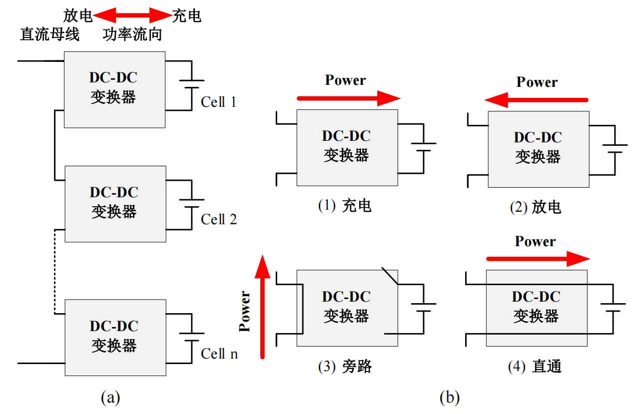
The modular integrated distributed energy storage battery system is shown in Figure 9 (a). The system connects the input terminals of each bidirectional DC-DC converter in series, and the output terminals are respectively connected to the battery cells. Each module can perform bidirectional current/voltage mode control to achieve different charging and discharging rates for different modules. Charging and discharging can also be achieved by charging and discharging as shown in Figure 9 (b) The four working modes of bypass and through enable the charging and discharging of energy storage battery, as well as the regulation of DC bus voltage. These four working modes improve system safety and reliability. For input series modular charging systems, the input and output power of each module is controlled by the module port voltage. During the charging and discharging process, it is necessary to handle the charging and discharging power and balance power. Moreover, this scheme requires a DC bus with constant current output characteristics. Generally, the ordinary bus is mostly voltage type after being output by APFC, so an additional converter is often needed to convert it into a constant current form as the input of the system. At the same time, when the energy storage battery fails, this scheme needs to bypass the faulty battery cell. The larger the range of bus voltage variation, the greater the difficulty of control. Considering that each module is only connected to one energy storage battery cell, the cost is too high and the scalability is poor when many energy storage battery need to be used in series.
1.2.2 Multi transformer parallel distributed charging system
The basic topology of a multi transformer parallel distributed charging system is shown in Figures 10. Each energy storage cell in a series battery pack has a charger with a high-frequency transformer. The primary side of each high-frequency transformer is connected to the output of the same inverter circuit through a switch, that is, the inverter circuit and each high-frequency transformer are jointly connected to the AC bus. Therefore, each set of chargers operates independently. The system can control the switch between the high-frequency transformer and the AC bus, connect the high-frequency transformer, and then independently charge n energy storage battery through rectification and synchronization buck circuits. After the energy storage battery are fully charged, the switch on the AC bus can be cut off. The charging current of the energy storage battery unit can be controlled by the synchronous Buck circuit to change the duty cycle of the switching tube, thereby achieving the charging function of the series battery pack.
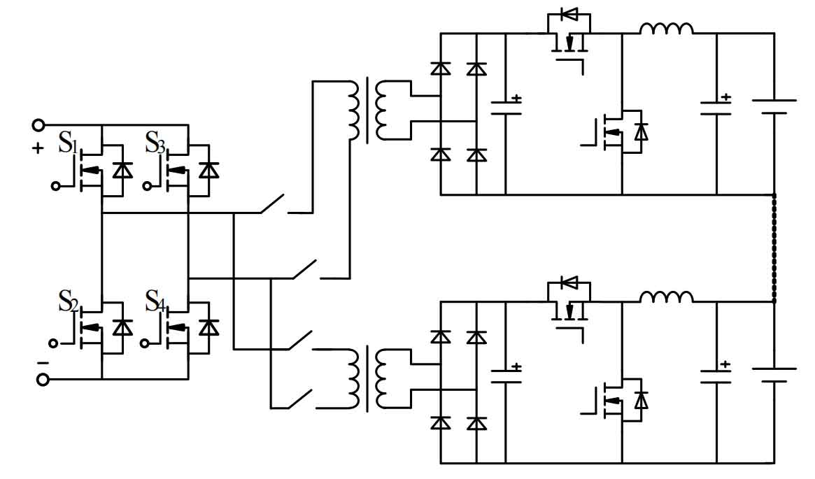
This charging system can achieve good charging effects with clear and single control objectives. However, the high cost brought about by the volume and quantity of transformers greatly limits the scalability of the system. In addition, the system has a high requirement for the reliability of the front-end inverter. The power level of a single inverter front-end is directly proportional to the number of series units, and the voltage level of the energy storage battery pack is limited.
1.2.3 Multi converter parallel distributed charging system
The multi variable converter parallel distributed charging system is a system that parallelly operates each module composed of energy storage battery and converters on the same DC bus, with high independence.
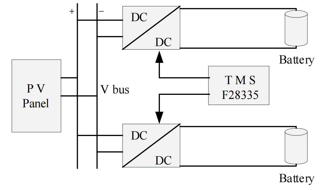
As shown in Figures 11, it is a portable bidirectional multi output solar charger proposed by Israeli scholars. Each energy storage battery of the charger is equipped with an independent bidirectional DC converter and battery management system. The input terminals of each bidirectional DC converter are connected in parallel to the same DC bus, and the voltage of the DC bus is provided by the solar panel. When the individual voltage of the energy storage battery reaches the upper and lower limits, the charger can be turned off or the bidirectional DC converter can be controlled to be in charging state, fundamentally eliminating the problem of imbalanced charging such as overcharging and undercharging of the battery pack. The status of each energy storage battery is transmitted to the main controller through the bus, which can achieve real-time monitoring and management of the energy storage battery. The entire system structure has advantages such as energy storage battery protection, plug and play functionality, and high scalability.
In summary, the multi converter parallel distributed charging structure has strong independence and high scalability. In the charging mode, the inconsistency of the energy storage battery pack can be avoided by controlling the charging current. At the same time, the parallel operation feature brings more energy transfer paths to the system, which is conducive to the regularization of subsequent balancing strategies. Therefore, this article adopts a multi converter parallel distributed balancing charging system.
1.3 Balanced control strategy
The development time of equilibrium control strategy technology is relatively short, and there is relatively little research on it. However, equilibrium control strategy is the decisive factor for achieving successful equilibrium effect and is an indispensable link. The equilibrium control strategy is formulated based on the equilibrium topology and the entire equilibrium system, and needs to be combined with equilibrium control variables to further find the optimal equilibrium path for imbalanced energy storage battery. The premise for selecting equilibrium control variables is that they can reflect the changes in the capacity of energy storage battery. At present, energy storage battery terminal voltage, energy storage battery SOC, and remaining capacity of energy storage battery are commonly used as equilibrium control variables. Based on the characteristics of these equilibrium control variables, an equilibrium objective function is constructed, and then the equilibrium strategy drives the corresponding equilibrium action to ultimately achieve the goal of energy storage battery equilibrium. The equilibrium control strategy can be divided into four categories based on the different equilibrium objective functions: extreme value type, average type, monotonic approaching type, and objective type.
(1) Extreme type
Extreme equilibrium strategy is a balancing action that involves selecting the maximum and minimum values of equilibrium control variables. It has the advantages of simple balancing program design, fewer parameters, and clear objectives, and is commonly used in practical engineering applications. However, this method has significant limitations. When the topology of the balancing circuit is not flexible enough, it may lead to poor balancing performance due to the long balancing path. At the same time, this method is single step execution, which means that only two balancing targets can be selected at a time for balancing action. The balancing speed is slow and not suitable for circuits with complex balancing paths.
(2) Average type
The average equilibrium strategy, as the name suggests, adds up each equilibrium control variable and takes its average value as the imbalance judgment condition, thereby dividing the energy storage battery in the energy storage battery pack into three categories: rich energy batteries, normal energy storage battery, and limited energy storage batteries. Then, based on the specific equilibrium topology, the optimal equilibrium path is formulated for the subsequent process. The randomness of this strategy is too strong, and different imbalanced conditions require a lot of discussion on balancing action classification. As the number of series energy storage battery increases, the complexity of the program sharply increases, which is not conducive to expansion. If the balancing paths of the balancing topology are not rich enough, there will still be balancing overlap, which will prolong the balancing time.
(3) Monotonic convergence type
Emphasis is placed on the planning of the equilibrium objective function and subsequent equilibrium actions, so that the process from the initial state of the energy storage battery pack to the equilibrium objective variable is monotonic, greatly reducing the phenomenon of equilibrium overlap and shortening the equilibrium time. Using it as a rule constraint for balancing strategy selection is very convenient for establishing more direct balancing paths and regularizing balancing actions in more complex balancing systems. This strategy is suitable for balancing between individual cells and balancing speed in multi-layer balancing systems.
(4) Target type
In order to avoid the phenomenon of over balancing as much as possible, a balancing control strategy based on the objective balancing objective function is proposed. This strategy calculates the balancing objective variable through balancing performance parameters, divides different imbalanced energy storage battery groups based on the relationship between the balancing control variable and the balancing objective, and then opens the corresponding balancing action. Whenever the difference between an energy storage battery cell and the balancing objective is less than a certain threshold, Then the individual cell deviates from the equilibrium action range, ultimately causing the equilibrium control variables of each energy storage battery cell to approach the equilibrium target. After classifying imbalanced energy storage battery groups, the goal based balancing strategy also needs to be coordinated with corresponding balancing path planning to complete the balancing of energy storage battery. Similarly, if the balancing path is not well formulated, there will be an over balancing phenomenon.
3. Summary
In response to the current situation of slow charging speed, low efficiency, and uneven charging in charging systems, this paper proposes a new distributed balancing charging system with balancing function based on all patents of Voltoffer.
The system adopts a distributed parallel charging structure combined with a four cell direct balancing topology to form the entire system structure. According to the system’s functions, the distributed balanced charging system can be regarded as two layers of units, and from a macro perspective, the charging balance and cross group discharge balance of the distributed charging system of the upper unit and the four cell balancer of the lower unit are combined, Implement dynamic self balancing of energy storage battery cells within lower level units from a microscopic perspective.
The Voltoffer uses standard lithium iron phosphate batteries with a capacity of 20Ah, with charging and discharging cut-off voltages of 3.65V and 2.5V, respectively, and a nominal voltage value of 3.2V. The lower unit of a distributed balancing charging system is composed of four sections of lithium iron phosphate batteries and a coupled inductor type multipath direct balancing topology, namely a four cell equalizer. Each lower unit has a nominal voltage of 12.8V, and the standard charging voltage of the charging system can be dynamically expanded and reduced according to the voltage multiples of the lower unit according to actual needs, which can adapt well to energy storage systems of different charging levels.
The main research content of this article is divided into the following four parts:
(1) Principle Analysis and Simulation of Distributed Balanced Charging System with Series Energy Storage Power Sources
Introduce the basic circuit of the distributed balanced charging system for the series energy storage power supply, and analyze the working principle and operating mode of the bidirectional DC converter and four cell equalizer. Then, derive the model of the four cell equalizer, obtain relevant balance indicators, and conduct simulation verification.
(2) Design of Magnetic Components and Converter Control Loop for Balanced Charging System
Design the magnetic components of the balanced charging system according to the system indicators. Establish small signal models for bidirectional DC converters in different modes, design control loop parameters for bidirectional DC converters in different modes based on the system’s charge discharge balance requirements, analyze their stability through Bode plots, and finally build closed-loop simulation models for verification.
(3) Analysis of Balanced Strategy for Distributed Balanced Charging System with Series Energy Storage Power Sources
Based on the structural characteristics of a distributed balanced charging system with series energy storage power sources, a charging balance strategy is proposed. The relationship between intra group balance and cross group balance is analyzed. Based on the selected balance control variables, a time slice allocation parallel discharge balance strategy that balances efficiency and speed is proposed. The relationship between the internal resistance loss of energy storage battery and the size and position of time slices is analyzed, and the optimal balance scheme under different situations is obtained.
(4) Functional Experiment and Balance Strategy Verification of Distributed Balanced Charging System with Series Energy Storage Power Sources
Introduce the platform structure of a distributed balanced charging system for series energy storage power sources, and then conduct basic functional experimental verification and related balancing index testing for independent and combined operation of bidirectional DC converters and four cell balancers. Design a time slice allocation parallel discharge balancing strategy simulation program and conduct two different forms of complex unbalanced energy storage battery pack balancing strategy verification.