
Low carbon, green, and intelligent transportation systems have become increasingly popular around the world. Energy storage modern trams have been recognized and promoted in many regions across the country in recent years due to their low energy consumption, low line investment, and no need to install power supply network cables. At present, energy storage power sources have certain application experience in the field of urban rail transit vehicles. The existing energy storage power sources used in modern energy storage trams are all installed at the roof position. During the assembly or maintenance process of energy storage power sources, workers need to climb the roof, touch the electrical connection copper bars, and disassemble the copper bar fasteners, which has shortcomings such as long maintenance time and personal safety hazards for maintenance workers. At the same time, the energy storage power supply system supplements energy through charging stations, so charging devices need to be installed next to the platform. This article will introduce a high-power and high-density energy storage power supply applied to hybrid (diesel electric) power multiple units. When the multiple units operate on non electrified mainlines without pantographs or charging stations, the energy storage power supply will be charged through the power pack configured by the multiple units and absorb the energy generated during the braking process, meeting the long-term traction needs of the multiple units.
1. Overview of Hybrid Electric Multiple Unit
1.1 Technical parameters of high-speed trains
The design speed of the high-speed train is 140 km/h, with a starting acceleration greater than 0.8 m/s2. The formation form is – D1+M1+M2+D2-, where D is the trailer (with driver’s cab and power pack), M is the high-speed train (with inverter and power bogie), – is the 10 A hook head driver’s cab end coupler according to the American Association of Railways (AAR) standard, and+is a semi permanent traction rod.
1.2 EMU traction system
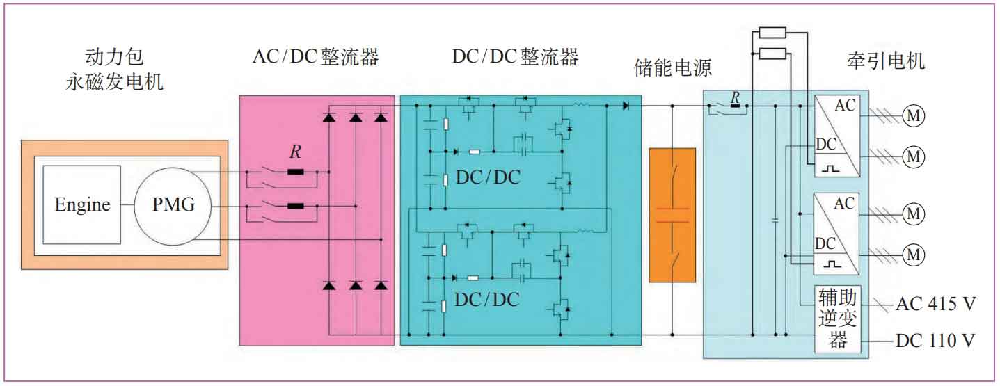
The traction system of the high-speed train adopts a diesel electric hybrid power scheme, mainly composed of a power pack (PMG), a permanent magnet generator (Engine), an AC/DC rectifier, a DC/DC rectifier, an energy storage power supply, a main auxiliary integrated converter, a braking resistor, and a traction motor (M). The power pack and energy storage power supply jointly supply power to the high-speed train. The electrical topology diagram is shown in Figure 1.
2. Overview of energy storage power supply
The energy storage power supply is an energy storage device for hybrid electric multiple units, installed at the bottom of the vehicle, and its main functions include:
(1) Under the traction condition of the train, both the energy storage power supply and the power pack supply power to the inverter. Due to the short-term high-power output characteristics of the energy storage power supply, the high-speed train can accelerate to the maximum operating speed in a short period of time;
(2) Under the coasting condition of the train, the power pack uses a small amount of power to maintain the constant speed of the train, and the excess power is used to charge the energy storage power supply for traction power output in the next stage;
(3) Under the braking condition of the train, the traction motor converts the kinetic energy of the train into electrical energy to supply power to the EMU, while storing excess energy in the energy storage power source to achieve energy recovery and recycling.
The energy storage power supply for hybrid electric multiple units consists of a chassis, 42 supercapacitor modules (including voltage balancing units), main control unit, current/voltage sensors, fuses, bipolar DC contactors, switch blades, cooling fans, etc. These components are designed in a modular tray manner. During the assembly and maintenance process of the energy storage power supply, workers do not need to touch the high-voltage electrical connection copper bar or disassemble the copper bar fasteners. They only need to push and pull the module tray to enable the energy storage power supply to self close/disconnect the high-voltage circuit, ensuring the safety of maintenance and repair.
The energy storage power supply adopts a 60000 F battery capacitor as the energy storage element. The positive electrode composite material of the 60000 F battery capacitor is nano grade lithium iron phosphate coated with carbon nanotubes and composite sugars as the carbon source. The negative electrode composite material is a ternary composite material of graphite, soft carbon, and hard carbon. This energy storage element breaks through the technical barriers of low energy density and volume density of supercapacitors (3000 F, 9500 F, etc.) in the past, and has high specific energy and high specific power The characteristics of longevity. The main technical parameters of energy storage power supply are shown in Table 1.
| Project | Parameter |
| Working voltage/V | DC 630-870 |
| Rated capacity/F | 714 |
| Rated current/A | 600 |
| Electricity consumption/kW · h | 38987 |
| Energy density/W · h · kg ^ -1 | 40 |
| Power density/W · kg ^ -1 | 2134 |
| Volume density/W · h · L ^ -1 | 70 |
| Control power supply/V | DC 110, tolerance -30% to 25% |
| Communication methods | Multi functional Vehicle Bus (MVB) |
The energy storage power supply adopts a suspended installation method from the bottom of the vehicle, and uses the exhaust of the passenger compartment air conditioning as the cooling source to ensure heat dissipation. The overall layout is shown in Figure 2.
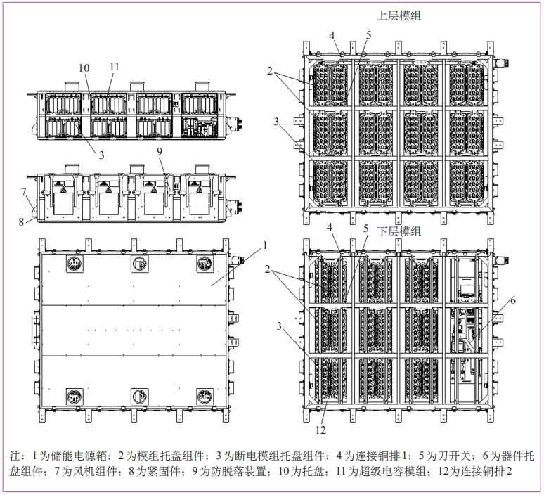
The main components of the energy storage power supply are 42 supercapacitor modules. In order to reduce the vertical and horizontal dimensions, the energy storage power supply box is designed with a structure of two layers of modules installed on top and bottom. The 42 supercapacitor modules are respectively installed on 21 trays, forming 14 module tray components and 7 power-off module tray components. Each column has 2 module tray components and 1 power-off module tray component, which are pushed and pulled into the box, During the push-pull process, it automatically switches on/off (using a knife switch) for connection. There are 6 fan components on each side of the energy storage power supply. The maintenance and repair of the fan does not require opening the cabinet door, and the fasteners of the fan components can be directly removed from the outside of the box. An anti falling device is designed on the door of the energy storage power supply cabinet to prevent the cabinet door from loosening and falling off. The electrical components of the energy storage power supply (such as bipolar DC contactors, current sensors, fuses, etc.) are designed to be modular, and all devices in the main circuit and control circuit are installed on the device tray assembly. The installation of the device tray assembly is also done by pushing and pulling.
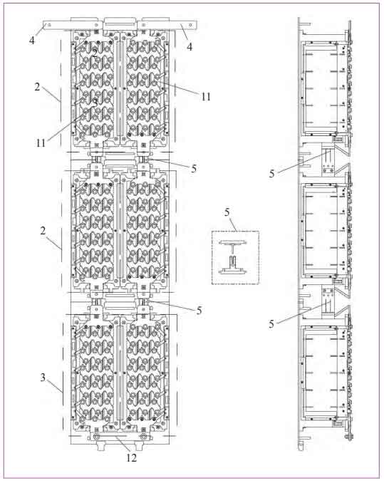
The electrical connection between the vertical supercapacitor modules adopts a knife switch form, as shown in Figure 3. During the assembly process of the energy storage power supply, first install 14 module tray components into the energy storage power supply box, then connect the horizontal supercapacitor modules with connecting copper bar 1 and fasteners, and then push the power-off module tray components that have been connected to the other side with connecting copper bar 2 in sequence. At this point, the circuits between the supercapacitor modules in the entire energy storage power supply box have been connected in series and closed, No need to manually touch the electrical connection components on the high-voltage circuit (such as copper bars, fasteners, etc.).
3. Electrical design of energy storage power supply
3.1 Main circuit schematic design
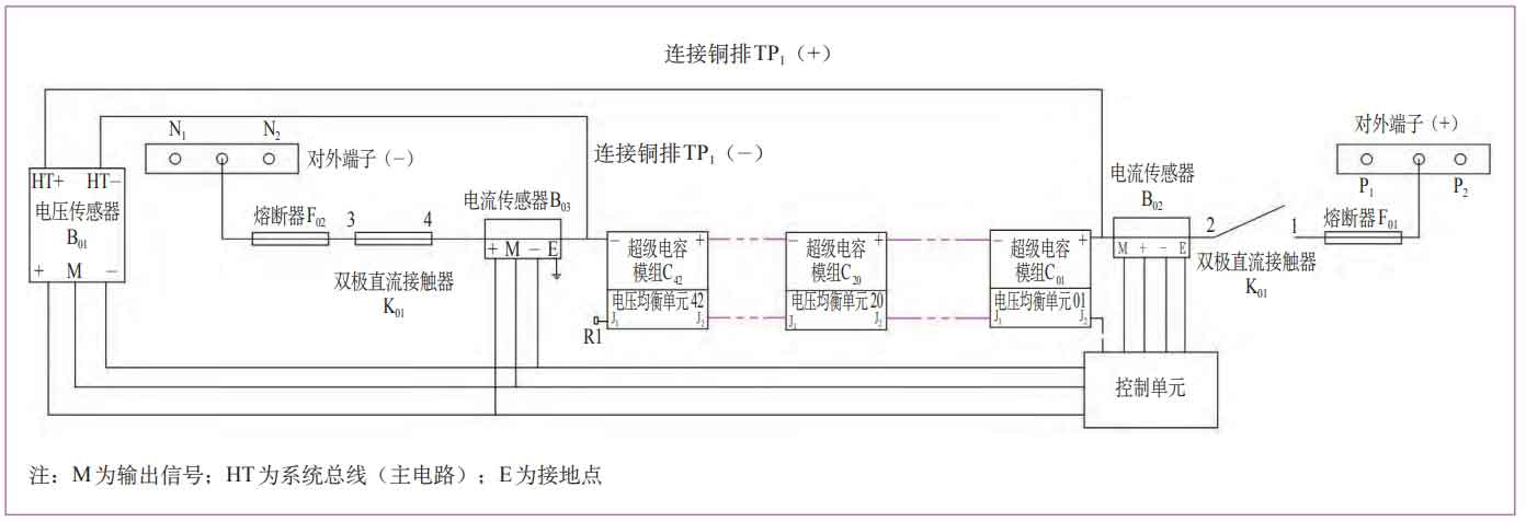
The main circuit schematic diagram of the energy storage power supply is shown in Figure 4, mainly composed of the positive pole fuse (F01), bipolar DC contactor (K01), current sensor (B02), supercapacitor module and circuit (C01-C42), current sensor (B03), negative pole fuse (F02), voltage sensor (B01), control unit, and externally connected terminals (such as P1, P2, N1, N2) of the input circuit.
3.2 Working principle
When the voltage of the energy storage power supply is within DC 630-870 V, it can provide traction for the high-speed train. At this time, the energy storage power supply passes through B02, K01, and F01 to supply power to the traction system of the high-speed train; When the voltage of the energy storage power supply is lower than DC 630 V, the energy generated during the braking process of the diesel engine or high-speed train charges the energy storage power supply, that is, after passing through F01, K01, and B02, it charges the supercapacitor module. The control unit is responsible for monitoring the operation status of the energy storage power supply. The voltage balancing units on the 42 supercapacitor modules are connected in series through internal communication interfaces J1 and J2 for controller local area network (CAN) communication (terminal resistor R1 is installed on module C42). The collected voltage, temperature and other status data of the 42 supercapacitor modules are sent to the control unit through CAN communication, including positive and negative fuses, current sensors, etc The status data of voltage sensors and other devices are sent to the control unit through hard wires, and then the control unit sends the calculated output voltage, temperature, and device status data to the high-speed train to achieve real-time monitoring of the energy storage power supply by the high-speed train.
3.3 Protection circuit design
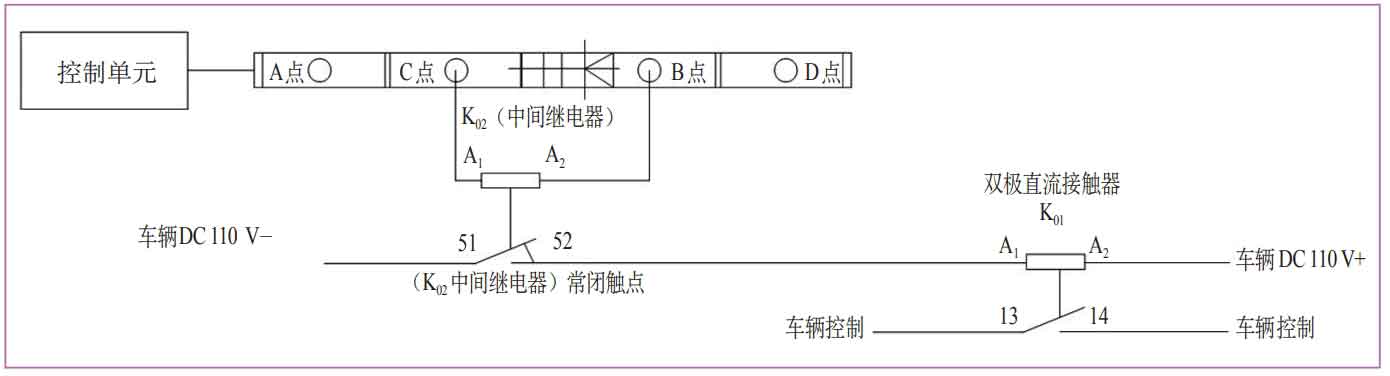
The energy storage power supply system and the traction system of the high-speed train both have the function of cutting off the DC 110 V power supply system, that is, controlling the on/off of K01 through a hard wire circuit. As shown in Figure 5, the energy storage power supply cuts off the DC 110 V power supply through an internal control unit, a diode four wire terminal (V01), an intermediate relay (K02), and then a bipolar DC contactor (K01) for control; The cutting off of energy storage power by the high-speed train is achieved by controlling the bipolar DC contactor.
The status of the intermediate relay (K02) is shown in Table 2.
| Energy storage power supply status | Intermediate relay coil | Intermediate relay switch status |
| Module over temperature alarm: Temperature ≥ 55 ℃ for 5 minutes or module temperature ≥ 60 ℃ for 2 seconds | Power on | Disconnect |
| Single cell overvoltage alarm: Single cell voltage ≥ 4.2 V | Power on | Disconnect |
| Over temperature alarm module temperature ≤ 52 ℃ | Power loss | Close |
| After the overvoltage alarm module fault is resolved | Power loss | Close |
When the energy storage power management system (CMS) detects an over temperature alarm or overvoltage alarm in the Cxx module, the control unit sends a request to cut off the energy storage power signal to the high-speed train. After 5 seconds, the control unit provides a DC 24V signal (high level control unit) to power on the A1 coil of K02, with contacts 51 and 52 normally closed. After manually cutting off the energy storage power signal, the high-speed train completed unloading and disconnected the DC 110 V signal (low level). The A1 and A2 coils of K01 lost power. At this time, the normally open contacts 13 and 14 of K01 in Figure 5 were disconnected, and the main contacts 1 and 2 of K01 in Figure 4 were disconnected.
When the over temperature alarm module temperature is ≤ 52 ℃, the module high temperature alarm fault is cleared; After the overvoltage alarm module fault is resolved, the DC 24 V signal is disconnected (low level), the coil A1 of K02 loses power, and the normally closed contacts 51 and 52 of K02 are closed. At this time, K02 is in a state of power loss, and this state is reported to the high-speed train unit. The high-speed train unit continues to judge whether the contact can be closed and execute the corresponding command based on other conditions. When the high-speed train detects that the contactor can be connected, it provides a DC 110 V signal (high level). At this time, the A1 and A2 coils of K01 are powered on, the normally open contacts 13 and 14 close, and K01 is connected.
The corresponding states of intermediate relay (K02), high-speed train DC 110 V control signal, and bipolar DC contactor (K01) are shown in Table 3.
| Control unit control signal | K02 | EMU DC 110 V control signal | K01 |
| High level | Disconnect | Low level | Disconnect |
| High level | Disconnect | High level | Disconnect |
| Low level | Low level | Low level | Disconnect |
| Low level | Low level | High level | Close |
The energy storage power supply is equipped with a smoke and temperature detector inside the box. When smoke is detected inside the box, the fire alarm of the high-speed train will be triggered. At this time, the DC 110 V power supply of the high-speed train is disconnected, and the A1 and A2 coils of K01 lose power. The normally open contacts 13 and 14 are disconnected, and the main contacts 1 and 2 are also disconnected. The energy storage power supply of the high-speed train is cut off.
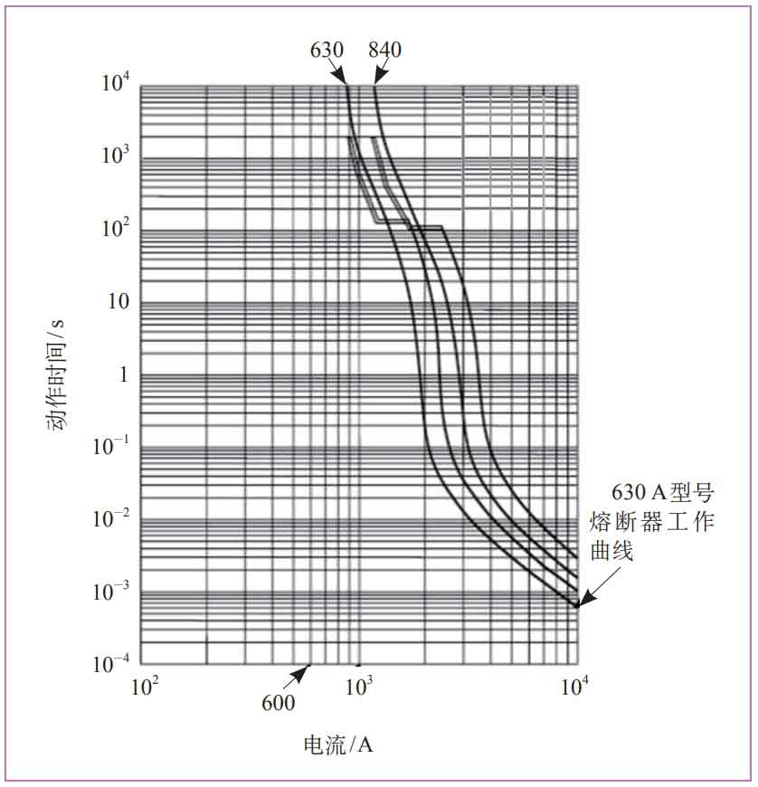
The positive and negative input terminals of the energy storage power supply are respectively equipped with fuses for short-circuit and overcurrent protection of the main circuit. The characteristic curve of the fuses is shown in Figure 6. When the working current of the energy storage power supply is 600 A, the action time of the fuse (i.e. cutting off the main circuit after melting) is greater than 10000 seconds; When the working current of the energy storage power supply is 900 A, the action time of the fuse is greater than 4000 s; When the working current of the energy storage power supply is 1000 A, the operating time of the fuse is 900-1000 seconds. The continuous charging and discharging current of the energy storage power supply is 600 A, and the instantaneous (within 30 seconds) peak charging and discharging current is 900 A. Therefore, its configured fuse can effectively provide short circuit and overcurrent protection for the main circuit.
The working temperature range of supercapacitors is -20~55 ℃, and each module in the energy storage power supply is equipped with one temperature sensor. The energy storage power management system monitors the temperature of all supercapacitor units inside the energy storage power supply. When the average temperature is detected to exceed 45 ℃, the energy storage power supply sends a warning signal, suggesting that the high-speed train should be repaired after returning to the depot; When the average temperature exceeds 55 ℃, the energy storage power supply sends an over temperature alarm signal and interrupts the use of the energy storage power supply through K01.
4. Performance characteristics of energy storage power supply
(1) Energy conservation and environmental protection. When a hybrid electric multiple unit is being towed, the energy storage power supply can provide high power for the train to start and accelerate in a short period of time. Therefore, small power, small volume, and small mass diesel power packs can be configured to reduce the mass and wheel rail impact of the multiple unit, and can also reduce vehicle noise; When braking, the braking energy feedback from the traction motor can be absorbed and stored by the supercapacitor for use in the next train start, achieving energy recycling and achieving energy-saving and emission reduction effects.
(2) Safe and reliable. The fire protection design meets the latest international standard EN 45545-2: 2013 “Railway applications – Fire protection of railway vehicles – Part 2: Requirements for fire behavior of materials and components”; The high-speed train can monitor the status of energy storage power in real time; The energy storage power supply and the traction system of the high-speed train both have the protection function of cutting off the entire power supply system, which improves the safety performance of the high-speed train.
(3) Convenient for maintenance. During the assembly and maintenance process of energy storage power supplies, workers do not need to touch the high-voltage electrical connection copper bars or disassemble the copper bar fasteners. Instead, they self power off the supercapacitors through the push-pull module tray.
5. Application
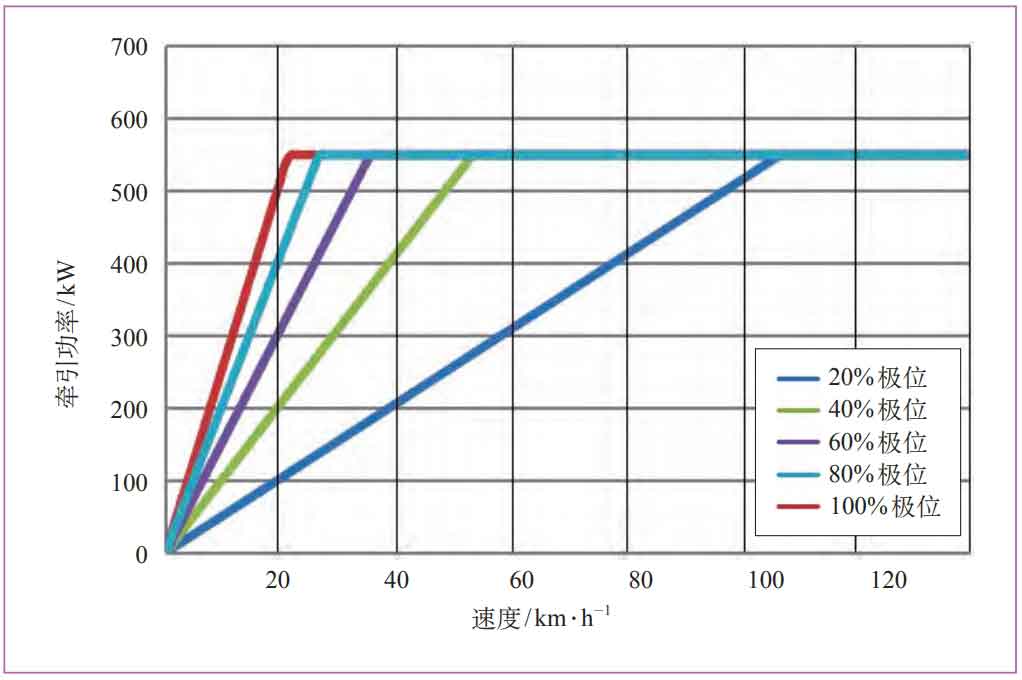
The energy storage power supply system described has been successfully applied to a certain high-speed train project, with all indicators meeting relevant standards and design requirements, and running stably and reliably, meeting the requirements of high-speed train operation. According to the traction performance test of energy storage power supply conducted on a certain high-speed train, the traction characteristic curve and standard traction characteristic curve drawn after recording data at various speeds and traction poles are shown in Figure 7 and Figure 8, respectively.
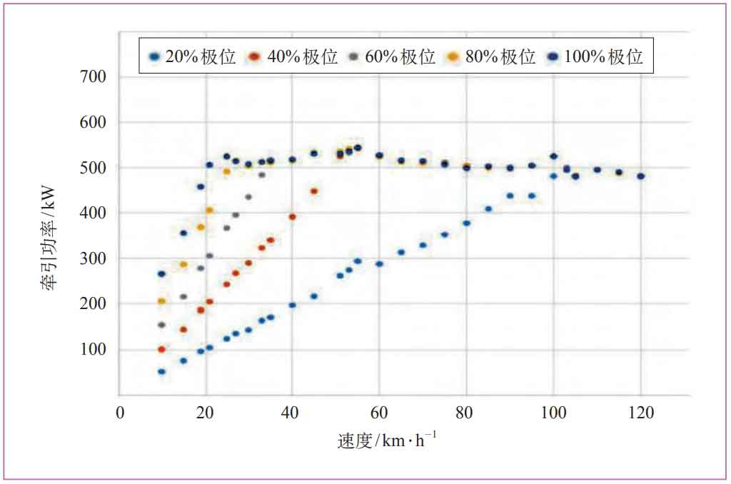
According to Figure 8, the traction output power of the high-speed train at a speed of 20 km/h at 100% pole position is 500 kW, and then it continues to output constant power until the high-speed train reaches 120 km/h. During the traction test of the high-speed train, the energy storage power supply achieved a traction output power of over 500 kW at a speed of 20 km/h, as shown by the dark blue dots in Figure 7. Therefore, the test data of the energy storage power supply developed in this article meets the requirements of the high-speed train, has the ability to continuously charge and discharge large currents, and has a stable power performance curve.
6. Conclusion
This paper provides a detailed introduction to the design and structure of energy storage power sources, and finally verifies through specific examples that their corresponding indicators meet the requirements of high-speed trains. The successful development of this energy storage power source has achieved the environmental goals of energy conservation and emission reduction, providing a good reference for the development and research of hybrid electric multiple unit systems. It can be used in locomotive energy storage systems, wind power generation, urban rail transit energy storage systems, electric multiple unit (EMU), communication, national defense and other fields, with a promising economic and social benefits prospect.