
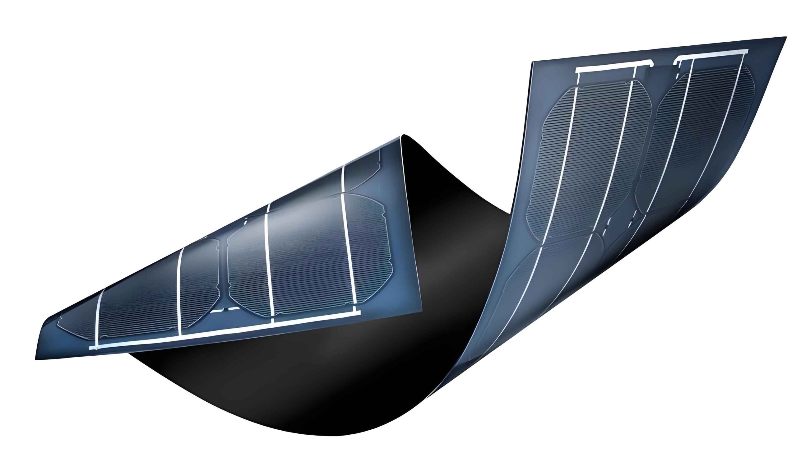
The quest for sustainable and cost-effective photovoltaic technologies has positioned thin film solar panels as a crucial alternative to conventional silicon-based cells. Among them, Cu(In,Ga)Se2 (CIGS) thin film solar panels have demonstrated remarkable power conversion efficiencies, surpassing 22% for laboratory-scale devices. However, the reliance on indium and gallium, which are relatively scarce and expensive elements, poses significant constraints on the terawatt-scale industrialization of CIGS technology. This limitation has catalyzed intense research into earth-abundant, non-toxic alternatives. Kesterite Cu2ZnSnS4 (CZTS) and its selenide counterpart Cu2ZnSn(S,Se)4 (CZTSSe) have emerged as the most promising absorbers for the next generation of thin film solar panels. These materials share a similar crystal structure and favorable optoelectronic properties with CIGS, such as a high absorption coefficient (>104 cm-1) and a tunable direct bandgap in the ideal range of 1.0-1.5 eV for single-junction solar cells.
Record-efficiency CZTSSe thin film solar panels, achieving up to 12.6%, have been fabricated using a device architecture directly inherited from CIGS technology: substrate/Molybdenum (Mo)/absorber/buffer/intrinsic-ZnO (i-ZnO)/Al-doped ZnO (AZO). In this structure, the buffer layer plays a pivotal role. It forms the primary p-n heterojunction with the p-type absorber, passivates interface states, and modifies the band alignment. Historically, cadmium sulfide (CdS) deposited by chemical bath deposition (CBD) has been the standard buffer layer for champion CIGS and CZTS devices. Despite its excellent performance, the use of toxic cadmium raises serious environmental and health concerns during manufacturing and throughout the product lifecycle. Therefore, developing high-performance, cadmium-free buffer layers is not merely an option but a fundamental requirement for the sustainable commercialization of kesterite-based thin film solar panels. Furthermore, replacing CdS (Eg ~2.4 eV) with a wider bandgap material could reduce parasitic absorption of high-energy photons, potentially increasing the short-circuit current density (Jsc) of the cell.
The search for effective Cd-free buffers is guided by stringent electronic and material requirements. An ideal buffer material for CZTS thin film solar panels must:
1. Possess a wide bandgap (>2.8 eV is desirable) to be optically transparent.
2. Exhibit n-type conductivity.
3. Form a favorable “spike-like” conduction band offset (CBO) with the CZTS absorber, typically in the range of 0 to 0.4 eV.
4. Facilitate a high-quality interface with low defect density to minimize carrier recombination.
5. Be compatible with low-cost, scalable deposition techniques.
The conduction band alignment at the absorber/buffer interface is arguably the most critical parameter. It profoundly influences the key device metrics: open-circuit voltage (Voc), short-circuit current density (Jsc), and fill factor (FF). The relationship between the CBO ($\Delta E_c$) and device performance can be conceptualized as follows:
A large positive CBO (a high “spike”) acts as a barrier for photogenerated electrons (minority carriers in the p-type absorber) traveling from the absorber to the buffer. This barrier increases the series resistance and can severely limit Jsc. Quantitatively, the electron current over a spike can be described by a thermally activated process:
$$ J_{sc} \propto \exp\left(-\frac{\Delta E_c}{kT}\right) $$
where a larger $\Delta E_c$ leads to an exponential decrease in collected current.
Conversely, a negative CBO (a “cliff”) means the conduction band minimum (CBM) of the buffer is lower than that of the absorber. This alignment eliminates the collection barrier but creates a pathway for enhanced interface recombination. Electrons from the absorber can easily spill into the buffer and recombine with holes at the interface states, leading to a significant reduction in Voc. The ideal scenario, as empirically perfected in CdS/CIGS junctions, is a small positive spike (0–0.4 eV). This spike is sufficiently low not to impede electron collection but high enough to block holes from the absorber from reaching the interface, thereby suppressing recombination and allowing for a high Voc.
Classification and Properties of Cd-free Buffer Materials
Research into cadmium-free buffers for kesterite thin film solar panels has largely focused on three families of materials: sulfides, oxysulfides, and oxides. Each family offers distinct advantages and challenges in terms of band alignment, interface quality, and deposition compatibility.
Sulfide-based Buffer Layers
Sulfides are a logical starting point due to their chemical similarity to the chalcogenide absorber. Zinc Sulfide (ZnS) and Indium Sulfide (In2S3) are the most prominent candidates.
Zinc Sulfide (ZnS): With a wide bandgap (~3.6-3.8 eV), ZnS offers excellent transparency. Early studies on CIGS thin film solar panels demonstrated promising efficiencies with CBD-ZnS buffers. However, its application in pure-sulfide or high-sulfur content CZTS devices has been problematic. Ultraviolet photoelectron spectroscopy (UPS) measurements reveal a very large conduction band offset with CZTSSe. The valence band offset (VBO) is found to be approximately 1.3 eV. Given the bandgaps of ZnS (Eg~3.6 eV) and CZTSSe (Eg~1.2 eV), the CBO is calculated to be:
$$ \Delta E_c = E_g^{buffer} – E_g^{absorber} – \Delta E_v $$
$$ \Delta E_c \approx 3.6\text{ eV} – 1.2\text{ eV} – 1.3\text{ eV} \approx 1.1\text{ eV} $$
This massive spike (>0.4 eV) creates a formidable barrier for electron collection, explaining the poor Jsc and device performance often observed in ZnS/CZTS thin film solar panels.
Indium Sulfide (In2S3): This material has shown greater promise, particularly for CZTSSe thin film solar panels. Its bandgap can vary from ~2.0 eV to over 2.8 eV depending on crystallographic phase and doping (e.g., with sodium). For a typical In2S3 layer (Eg ~2.1 eV) on CZTSSe (Eg ~1.2 eV), UPS measurements indicate a VBO of about 0.75 eV. This results in a near-ideal, small positive CBO:
$$ \Delta E_c \approx 2.1\text{ eV} – 1.2\text{ eV} – 0.75\text{ eV} \approx 0.15\text{ eV} $$
This favorable alignment minimizes electron collection barriers while still providing recombination suppression. Consequently, In2S3 has yielded some of the highest efficiencies for Cd-free kesterite thin film solar panels, exceeding 7.5%. A summary of key sulfide buffer properties is presented below.
| Material | Typical Bandgap (eV) | CBO with CZTS (Typical) | Key Advantages | Primary Challenges |
|---|---|---|---|---|
| CdS (Reference) | 2.4 | ~ +0.4 eV (Spike) | Well-optimized, excellent interface | Toxicity, narrow bandgap |
| ZnS | 3.6-3.8 | > +1.0 eV (Large Spike) | Wide bandgap, non-toxic | Unfavorable band alignment, high Rs |
| In2S3 | 2.0-2.8 | ~ 0 to +0.3 eV (Spike) | Favorable alignment for CZTSSe, good efficiency | Cost of In, process sensitivity |
Oxysulfide-based Buffer Layers
Oxysulfides, such as Zn(S,O) and In(S,O,OH), naturally form during CBD processes when oxygen incorporation is significant. These materials offer a tunable electronic structure—their bandgap and band positions can be adjusted by varying the sulfur-to-oxygen ratio.
For instance, Zn(S,O) films can have a bandgap tunable between that of ZnS (~3.6 eV) and ZnO (~3.3 eV). This tunability provides a crucial knob for engineering the CBO with the CZTS absorber. By increasing the oxygen content, the conduction band of the buffer can be lowered, potentially reducing an excessively high spike. This approach has been highly successful in CIGS thin film solar panels, where Zn(S,O) buffers have achieved efficiencies exceeding 18%. In CZTS devices, the lattice match between Zn(S,O) and the kesterite absorber (especially for sulfur-rich compositions) is beneficial for promoting epitaxial-like growth and reducing interface defect density. Efficiencies around 6-7% have been reported, demonstrating its potential as a viable Cd-free alternative.
Oxide-based Buffer Layers
Oxides represent an attractive class of materials due to their excellent chemical stability, wide range of available compounds, and compatibility with various deposition techniques like atomic layer deposition (ALD) and sputtering. The challenge lies in achieving the correct band alignment, as many oxides tend to form “cliff-like” interfaces with chalcogenide absorbers.
Zinc Oxide (ZnO): Direct application of ZnO as a buffer typically results in poor device performance due to a negative or near-zero CBO, leading to high interface recombination and low Voc. Its use highlights the critical need for band alignment engineering.
Alloyed Oxides (Zn1-xMgxO and Zn1-xSnxOy): This is where significant progress has been made. By alloying ZnO with other metals, its electronic properties can be finely tuned.
Zn1-xMgxO (ZMO): Adding magnesium to ZnO increases its bandgap. As the Mg content (x) increases, the conduction band minimum of ZMO rises. The CBO with CZTS can thus be tuned from a cliff towards a spike. For pure-sulfide CZTS thin film solar panels, which have a higher bandgap (~1.5 eV) than CZTSSe, optimizing the Mg fraction is essential to create a small positive spike. This approach has led to promising device results.
Zn1-xSnxOy (ZTO): Alloying with tin offers another effective pathway for band engineering. ZTO buffers have demonstrated exceptional performance in CIGS cells, matching the efficiency of CdS-buffered devices. For CZTS thin film solar panels, ALD-deposited ZTO has yielded a record efficiency of 9.0% for a fully cadmium- and selenium-free device (pure sulfide CZTS). This marks a watershed moment, proving that high-performance, truly “green” kesterite thin film solar panels are feasible. The success of ZTO is attributed to its ability to form a favorable band alignment and a high-quality interface with low defect density.
The band engineering principle can be summarized by considering the change in electron affinity ($\chi$) and bandgap ($E_g$) upon alloying. For an alloy A1-xBxO, the conduction band position relative to the vacuum level is approximately:
$$ E_C \approx -\chi_{alloy} $$
where $\chi_{alloy}$ is a composition-weighted average that can be adjusted by varying ‘x’ to achieve the desired $\Delta E_c$ with CZTS.
| Material | Bandgap Tunability (eV) | Deposition Method | Status in CZTS | Key Advantage |
|---|---|---|---|---|
| ZnO | ~3.3 (Fixed) | CBD, ALD, Sputtering | Poor performance (Cliff) | Simple, stable |
| Zn1-xMgxO | 3.3 ~ 4.0+ | Mainly ALD | Promising for pure-S CZTS | Widely tunable CBO |
| Zn1-xSnxOy | ~3.3 ~ 3.8 | ALD | Record for Cd-free pure-S CZTS (9.0%) | Excellent interface, ideal alignment |
| Zn(S,O) | 2.8 ~ 3.6 | CBD | Good for CZTSSe (~6-7%) | Tunable, low-cost deposition |
Performance Analysis and Remaining Challenges
Despite significant advances, the efficiency of Cd-free CZTS thin film solar panels still lags behind their CdS-buffered counterparts. This performance gap can be attributed to several interconnected challenges beyond just the bulk band alignment.
1. Interface Quality and Defect Chemistry: The buffer/absorber interface is a complex region where interdiffusion, secondary phase formation, and point defects dominate the electronic properties. CdS may have a unique ability to passivate surface defects on CIGS/CZTS, possibly through Cd2+ diffusion that creates a thin n-type surface layer. Reproducing this benign chemical interaction with alternative materials is difficult. Defects at the interface act as recombination centers (SRH recombination), severely limiting Voc. The recombination current density can be expressed as:
$$ J_{rec} \propto n_i \exp\left(\frac{qV}{2kT}\right) $$
where a high interface defect density increases the pre-factor, lowering Voc.
2. Band Alignment at Non-Ideal Interfaces: Theoretical models often assume abrupt, clean interfaces. In reality, interface dipoles, defect-induced band bending, and the presence of ultrathin interfacial layers (like MoSe2 at the back contact or ordered vacancy compounds at the absorber surface) can dramatically alter the effective band alignment seen by charge carriers. This makes predicting and controlling the CBO in real devices highly complex.
3. Optical and Electrical Trade-offs: While wider bandgap buffers like ZnS or ZMO reduce optical losses, they may introduce higher series resistance if not doped appropriately or if the CBO spike is too high. Optimizing the buffer requires balancing optical transparency ($T(\lambda)$) with electrical conductivity ($\sigma$) and optimal band alignment.
$$ J_{sc}^{gain} \propto \int_{300nm}^{\lambda_{buffer}} T(\lambda) \cdot \text{AM1.5}(\lambda) \, d\lambda $$
This gain must outweigh any losses from increased series resistance.
4. Scalability and Process Integration: Champion devices often use sophisticated, low-throughput techniques like ALD for buffer deposition. For thin film solar panels to be manufactured on a GW scale, the buffer deposition process must be scalable, fast, and robust. CBD, while scalable, may face challenges with material utilization and waste disposal. Developing spray pyrolysis, spatial ALD, or other high-throughput methods compatible with these novel buffer materials is an ongoing challenge.
Conclusion and Future Perspectives
The development of high-performance, cadmium-free buffer layers is a critical pathway toward the sustainable commercialization of kesterite-based thin film solar panels. Research has identified several promising material families. For CZTSSe devices, In2S3 and tunable Zn(S,O) buffers have demonstrated favorable band alignment and good efficiencies. For the ultimate goal of fully abundant, non-toxic, and selenium-free thin film solar panels, alloyed oxide buffers—specifically Zn1-xSnxOy (ZTO) and Zn1-xMgxO (ZMO)—have shown remarkable promise, with ZTO already achieving a record 9.0% efficiency for pure-sulfide CZTS.
Future progress hinges on a multi-faceted approach:
Fundamental Understanding: Advanced in-situ and operando characterization techniques are needed to probe the chemical and electronic structure of the buried buffer/absorber interface during processing and operation.
Band Engineering at the Atomic Scale: Further exploration of multi-component oxides, nitrides, or novel compounds to precisely tailor electron affinity and bandgap.
Interface Engineering: Intentional use of ultrathin interlayers or surface treatments on the CZTS absorber before buffer deposition to modify surface termination and defect states.
Process Innovation: Developing scalable, manufacturable deposition techniques for these advanced buffer materials that can be integrated into roll-to-roll or large-area panel production lines.
By addressing these challenges, the vision of producing low-cost, high-efficiency, and truly environmentally benign CZTS thin film solar panels on a global scale can be realized, contributing significantly to the world’s clean energy portfolio.