
In recent years, the global shift towards renewable energy has intensified, with solar power playing a pivotal role in sustainable development. As educators, we recognized the need to bridge the gap between theoretical knowledge and practical skills in electrical engineering programs. To address this, we embarked on developing an off-grid solar system practice platform that integrates innovative educational methodologies. This platform allows students to engage hands-on with real-world components, fostering a deeper understanding of renewable energy systems. The off-grid solar system serves as a cornerstone for experiential learning, enabling learners to explore system design, energy management, and advanced control strategies. Through this initiative, we aim to cultivate innovation and entrepreneurship among students, preparing them for challenges in the evolving energy sector.
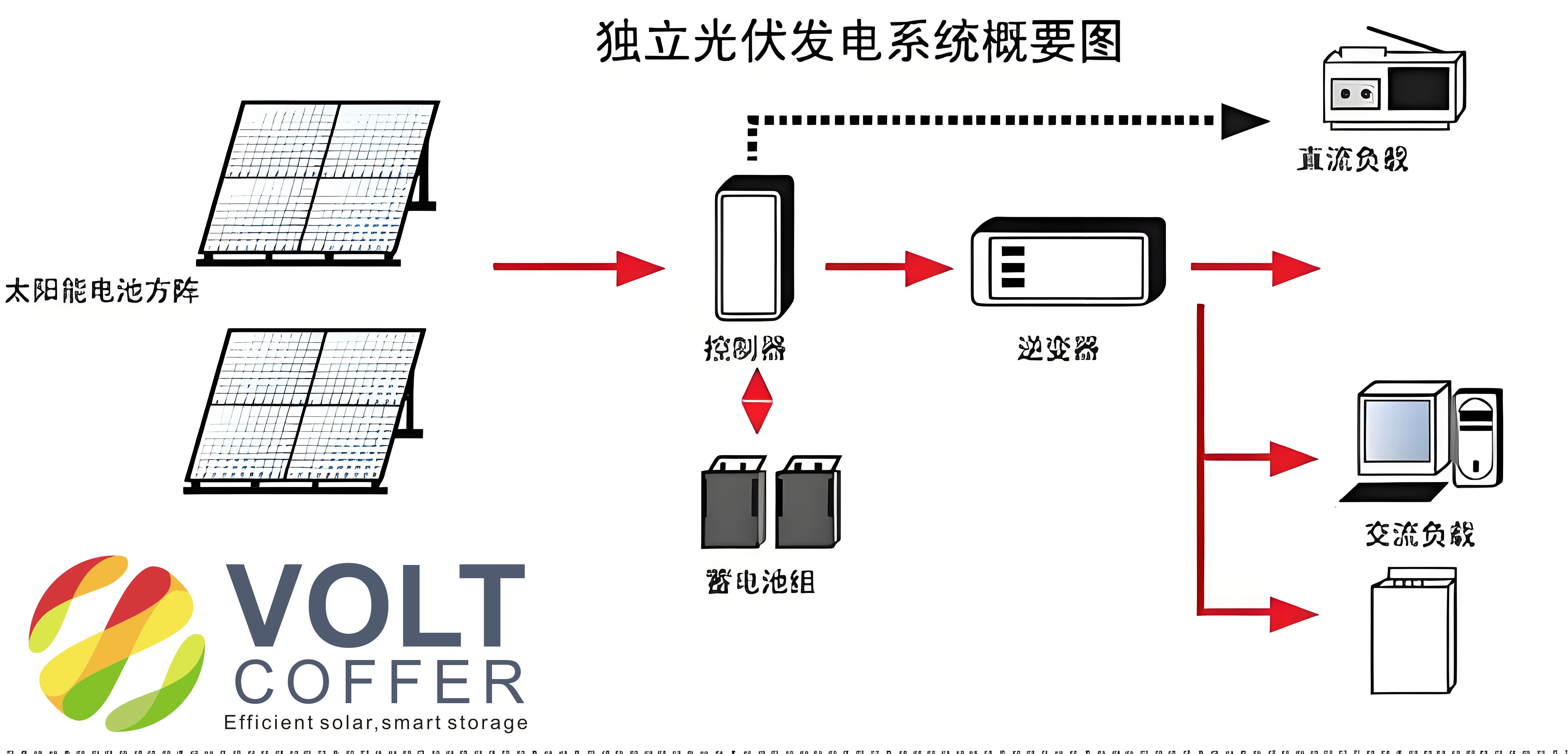
The off-grid solar system practice platform is designed as a modular, scalable setup that mimics standalone photovoltaic installations used in remote areas or for backup power. It comprises several key components: a photovoltaic array, a solar charge controller, a battery bank, an off-grid inverter, DC and AC loads, and a monitoring system. Each element is carefully selected to demonstrate core principles while allowing flexibility for experimentation. Below, we delve into the details of each component, supported by tables and mathematical models to elucidate their functions and interactions. The platform’s architecture emphasizes the importance of the off-grid solar system in modern engineering education, providing a sandbox for innovation.
The photovoltaic array forms the heart of the off-grid solar system, converting solar irradiance into electrical energy. We utilized multiple solar panels arranged in series and parallel configurations to achieve desired voltage and current levels. The power output of a solar panel depends on factors like irradiance and temperature, which can be modeled using the following equation for the current-voltage characteristic: $$I = I_{ph} – I_0 \left( \exp\left(\frac{V + I R_s}{n V_t}\right) – 1 \right) – \frac{V + I R_s}{R_{sh}}$$ where \(I\) is the output current, \(V\) is the output voltage, \(I_{ph}\) is the photocurrent, \(I_0\) is the reverse saturation current, \(R_s\) is the series resistance, \(R_{sh}\) is the shunt resistance, \(n\) is the ideality factor, and \(V_t\) is the thermal voltage. This equation helps students analyze how environmental conditions affect performance in an off-grid solar system. For our platform, we selected six 30W polycrystalline solar panels, configured as two series panels per string with three parallel strings, yielding a total output of 180W at 24V DC. The parameters of these panels are summarized in Table 1.
| Parameter | Value |
|---|---|
| Model | RGP-30 |
| Type | Polycrystalline |
| Rated Power | 30 W |
| Open Circuit Voltage (\(V_{oc}\)) | 21.5 V |
| Short Circuit Current (\(I_{sc}\)) | 1.75 A |
| Maximum Power Voltage (\(V_{mp}\)) | 17.5 V |
| Maximum Power Current (\(I_{mp}\)) | 1.71 A |
| Temperature Coefficient of \(V_{oc}\) | -0.32 %/°C |
The solar charge controller is critical for regulating energy flow in the off-grid solar system, ensuring efficient battery charging and protection. We implemented a maximum power point tracking (MPPT) algorithm to optimize power extraction from the photovoltaic array. The MPPT technique, specifically the incremental conductance method, adjusts the operating point to maintain the derivative of power with respect to voltage at zero: $$\frac{dP}{dV} = 0 \quad \text{where} \quad P = V \times I$$ This algorithm continuously monitors the array voltage and current, updating the duty cycle of a DC-DC converter to track the maximum power point. For our platform, we chose a Tracer4215BN controller, which features an MPPT efficiency of up to 99.5% and supports RS-485 communication for data monitoring. The controller’s specifications are detailed in Table 2, highlighting its role in managing the off-grid solar system’s energy harvest.
| Parameter | Value |
|---|---|
| Model | Tracer4215BN |
| MPPT Efficiency | 99.5% |
| System Voltage | 12/24 V DC Auto |
| Max PV Input Power (12V) | 520 W |
| Max PV Input Power (24V) | 1040 W |
| Rated Load Current | 20 A |
| Communication | RS-485 |
Energy storage in the off-grid solar system is handled by a battery bank, which stores excess energy for use during periods of low irradiance. We employed lead-acid batteries due to their reliability and cost-effectiveness. The state of charge (SOC) of a battery can be estimated using the Coulomb counting method: $$\text{SOC}(t) = \text{SOC}_0 – \frac{1}{C_n} \int_0^t I(\tau) \, d\tau$$ where \(\text{SOC}_0\) is the initial state of charge, \(C_n\) is the nominal capacity, and \(I\) is the battery current. For our setup, we used two 12V, 24Ah batteries connected in series to form a 24V DC system. This configuration ensures sufficient energy buffer for the off-grid solar system, supporting various loads. Table 3 outlines the battery specifications, emphasizing their importance in maintaining system stability.
| Parameter | Value |
|---|---|
| Model | 6-GFM-24 |
| Type | Lead-Acid (VRLA) |
| Rated Voltage | 12 V |
| Rated Capacity | 24 Ah |
| Series Configuration | 2 batteries for 24 V |
| Energy Storage | 576 Wh |
The off-grid inverter converts DC power from the battery bank to AC power for household appliances, employing advanced modulation techniques like space vector pulse width modulation (SVPWM). The SVPWM algorithm generates a rotating voltage vector by switching inverter states, defined as: $$\vec{V}_{ref} = \frac{2}{3} \left( V_a + a V_b + a^2 V_c \right) \quad \text{where} \quad a = e^{j\frac{2\pi}{3}}$$ This method minimizes harmonic distortion and improves efficiency in the off-grid solar system. We selected an STI1500-24-220V inverter, which produces a pure sine wave output with low total harmonic distortion (THD ≤ 2%). Its key parameters are listed in Table 4, demonstrating its capability to handle typical AC loads in an off-grid solar system.
| Parameter | Value |
|---|---|
| Model | STI1500-24-220V |
| Rated Power | 500 W |
| Output Voltage | 220/230 V AC |
| Frequency | 50 Hz ± 0.2% |
| Waveform | Pure Sine Wave |
| THD | ≤ 2% |
| Efficiency | > 90% |
Load management is integral to the off-grid solar system, encompassing both DC and AC loads. DC loads, such as LED lights, operate directly from the battery voltage, while AC loads, like fans or computers, require the inverter. The power balance in the system can be expressed as: $$P_{\text{PV}} = P_{\text{load}} + P_{\text{battery}} + P_{\text{losses}}$$ where \(P_{\text{PV}}\) is the photovoltaic power, \(P_{\text{load}}\) is the load power, and \(P_{\text{battery}}\) is the battery charging/discharging power. This equation helps students optimize energy usage in the off-grid solar system. For our platform, we included variable resistors as DC loads and standard appliances as AC loads, allowing for dynamic testing and analysis.
Monitoring and communication are vital for real-time oversight of the off-grid solar system. We implemented a software suite that includes PC-based applications and mobile apps for remote access. The system uses RS-485 for local communication and Wi-Fi for wireless monitoring, enabling data logging and parameter configuration. The monitoring software displays key metrics such as voltage, current, power, and state of charge, using mathematical models to predict system performance. For instance, the battery’s depth of discharge (DOD) is calculated as: $$\text{DOD} = 1 – \text{SOC}$$ which aids in preventing over-discharge. This comprehensive approach ensures that students can interact with the off-grid solar system through multiple interfaces, enhancing their learning experience.
In designing the off-grid solar system practice platform, we focused on scalability and interoperability. The modular nature allows students to reconfigure components, such as adding more solar panels or batteries, to study system behavior under different conditions. For example, the impact of shading on the photovoltaic array can be analyzed using the following equation for mismatch losses: $$P_{\text{loss}} = \sum_{i=1}^n P_i – P_{\text{min}} \times n$$ where \(P_i\) is the power of each panel and \(P_{\text{min}}\) is the minimum power in the string. This hands-on experimentation with the off-grid solar system fosters critical thinking and problem-solving skills.
The implementation phase involved assembling the components and integrating the software. We conducted rigorous testing to validate the off-grid solar system’s performance, measuring parameters like efficiency and response time. The MPPT controller’s effectiveness was verified by comparing theoretical and actual power outputs, using the formula: $$\eta_{\text{MPPT}} = \frac{P_{\text{actual}}}{P_{\text{max,theoretical}}} \times 100\%$$ Similarly, the inverter’s output quality was assessed through harmonic analysis, ensuring compliance with standards. These tests provided students with practical insights into the off-grid solar system’s reliability and limitations.
Operation of the off-grid solar system platform involves continuous monitoring and data analysis. Students can observe how environmental factors, such as temperature changes, affect system efficiency. The temperature dependence of the solar panel voltage is given by: $$V(T) = V_{\text{STC}} + \beta_V (T – T_{\text{STC}})$$ where \(V_{\text{STC}}\) is the voltage at standard test conditions, \(\beta_V\) is the temperature coefficient, and \(T\) is the panel temperature. By collecting data over time, learners can model the off-grid solar system’s behavior and propose improvements, such as adding cooling mechanisms or optimizing battery cycling.
Educational outcomes from the off-grid solar system practice platform have been profound. Students gain proficiency in system design, control algorithms, and energy management, which are essential for careers in renewable energy. The platform’s emphasis on the off-grid solar system aligns with global trends, preparing learners for innovative projects. Moreover, the hands-on approach encourages teamwork and entrepreneurship, as students develop solutions for real-world challenges. For instance, they might design a low-cost off-grid solar system for rural electrification, applying knowledge from the platform.
In conclusion, the development of this off-grid solar system practice platform has transformed our educational methodology, bridging theory and practice. The integration of mathematical models, tables, and real components provides a holistic learning environment. As we continue to refine the platform, we aim to incorporate emerging technologies, such as IoT and AI, to further enhance the off-grid solar system’s capabilities. This initiative not only advances engineering education but also contributes to sustainable development by promoting renewable energy adoption. The off-grid solar system remains a central theme in our curriculum, inspiring the next generation of innovators.