
Provide a basic introduction to the mature photovoltaic power generation currently available, mainly focusing on the use of roofs or other open spaces in civil buildings for photovoltaic power generation. Introduce the composition of photovoltaic power generation, summarize several common solar modules, and express the most basic design knowledge in photovoltaic electrical engineering. Describe the expression methods of electrical construction drawing design.
1.Composition of photovoltaic power generation system
The photovoltaic power generation system includes solar panels (photovoltaic modules), a combiner box that converts electrical energy into photovoltaic arrays, and a DC distribution box that controls DC current. If there is a need for energy storage, a battery (group) needs to be set up. As the final output power supply is AC 220V or AC 380V, a DC to AC inverter needs to be configured, which is converted to AC 220V or AC 380V voltage level and then distributed, An AC distribution box needs to be installed (which can be integrated with the inverter). If it needs to be connected to a higher voltage level public power supply system, a step-up transformer needs to be installed. In addition, when the electricity generated by photovoltaic power plants exceeds the usage load, it is recommended to install anti reverse current devices and monitoring systems for photovoltaic operation. For example, a certain project installs 1000 230 Wp photovoltaic modules, 10 intelligent combiner boxes, 5 DC distribution cabinets, 5 250 kW grid connected inverters, 1 AC distribution cabinet, 1 10KVS11-1250 transformer, and 1 comprehensive monitoring system.
1.1 Solar panels
Solar panels are the core part of solar power generation systems, completing photoelectric conversion, which can be stored in batteries or directly drive the load to work. Common photovoltaic modules are divided into types such as silicon photovoltaic modules, thin film photovoltaic modules, and concentrated photovoltaic modules.
(1) Silicon batteries.
① Crystalline silicon photovoltaic modules are divided into monocrystalline silicon and polycrystalline silicon. Monocrystalline silicon batteries emerged earliest and are the most mature solar photovoltaic cells in terms of technology. They are also a type of silicon based solar cell currently produced on a large scale. The efficiency of monocrystalline silicon batteries can reach 13% to 20%, which is higher than that of polycrystalline silicon. Due to the need for monocrystalline silicon batteries to be made into circular or square corners, they are easy to identify.
② Polycrystalline silicon wafers do not require single crystal drawing process, and their unit energy consumption is slightly lower than that of monocrystalline silicon. Their shape is no longer limited, and they can be processed into a shape that matches photovoltaic modules. The efficiency of polycrystalline silicon cells can reach 10% to 18%, but due to the utilization of all edges and corners, silicon raw materials are saved, and their cost-effectiveness is high. They are currently the most mainstream photovoltaic cells.
③ Amorphous silicon batteries are made by attaching amorphous silicon grains to the substrate. The material is silicon, but it no longer exists in crystalline form. The process is simple, the consumption of silicon raw materials is less, and the price is also lower (crystalline silicon components
The price is around 5 yuan/Wp, and it can be made into a thin film, which is convenient for construction and various occasions. It is less affected by high temperature, but has lower efficiency.
(2) Thin film photovoltaic modules
The photoelectric conversion efficiency can reach about 17%, with low cost. Rare metals are mostly used and there are many types, but there is still room for improvement. Thin film photovoltaic cells made of raw material indium are too sensitive to structural defects, resulting in a low yield of high-efficiency batteries. Moreover, due to being a rare metal, mass production is somewhat difficult. Another type of cadmium telluride has a high light absorption rate and is also an ideal material for manufacturing thin films and high-efficiency photovoltaic cells. The manufacturing cost of cadmium telluride thin film photovoltaic cells is low, and cadmium is a toxic element that can cause environmental pollution and may cause physical harm to installation personnel.
(3) Concentrated photovoltaic modules
By collecting the sunlight shining on the module through optical devices, the solar cell (gallium arsenide) is used to convert the light energy into electrical energy, which is integrated into the system and supplied to the load. Due to focusing light, the module itself is thicker than the crystalline silicon module, making it inconvenient to use in highly demanding spatial environments.
1.2 Combiner box
The combiner box combines the electrical energy converted by the photovoltaic array together, converging the electrical energy of each group of strings. From an installation perspective, it should be noted that the requirements for outdoor electrical equipment are similar. The protection level of the equipment combiner box box should not be lower than IP54, and it is generally installed outdoors on the ground or under the purlins of photovoltaic modules. The box model and size are often set by the manufacturer, and may not be marked during construction drawing design.
1.3 Inverter
In many cases, solar modules directly output power sources such as DC12 V and 24 V, but in practical use, AC 220 V and AC 380 V are often required. Therefore, it is necessary to convert the DC power generated by solar power generation systems into AC power, and to use inverters that convert electricity from DC to AC. Photovoltaic grid connected inverters can be divided into two types: high-power centralized inverters and small series inverters. Utilizing the characteristics of rooftop power generation buildings, the installed capacity of photovoltaic equipment projects is generally small. It is recommended to use string inverters more often. Common string inverters in civil buildings have capacities of 10 kW, 15 kW, 20 kW, and 30 kW, 50 kW, etc.
1.4 Battery
Batteries are optional devices that often appear in small systems, usually lead-acid batteries. They can also be used as nickel hydrogen batteries, nickel cadmium batteries, or lithium batteries to store the electrical energy emitted by solar panels. During periods without daylight conditions, batteries can be used to power designated electrical equipment.
1.5 Solar controller
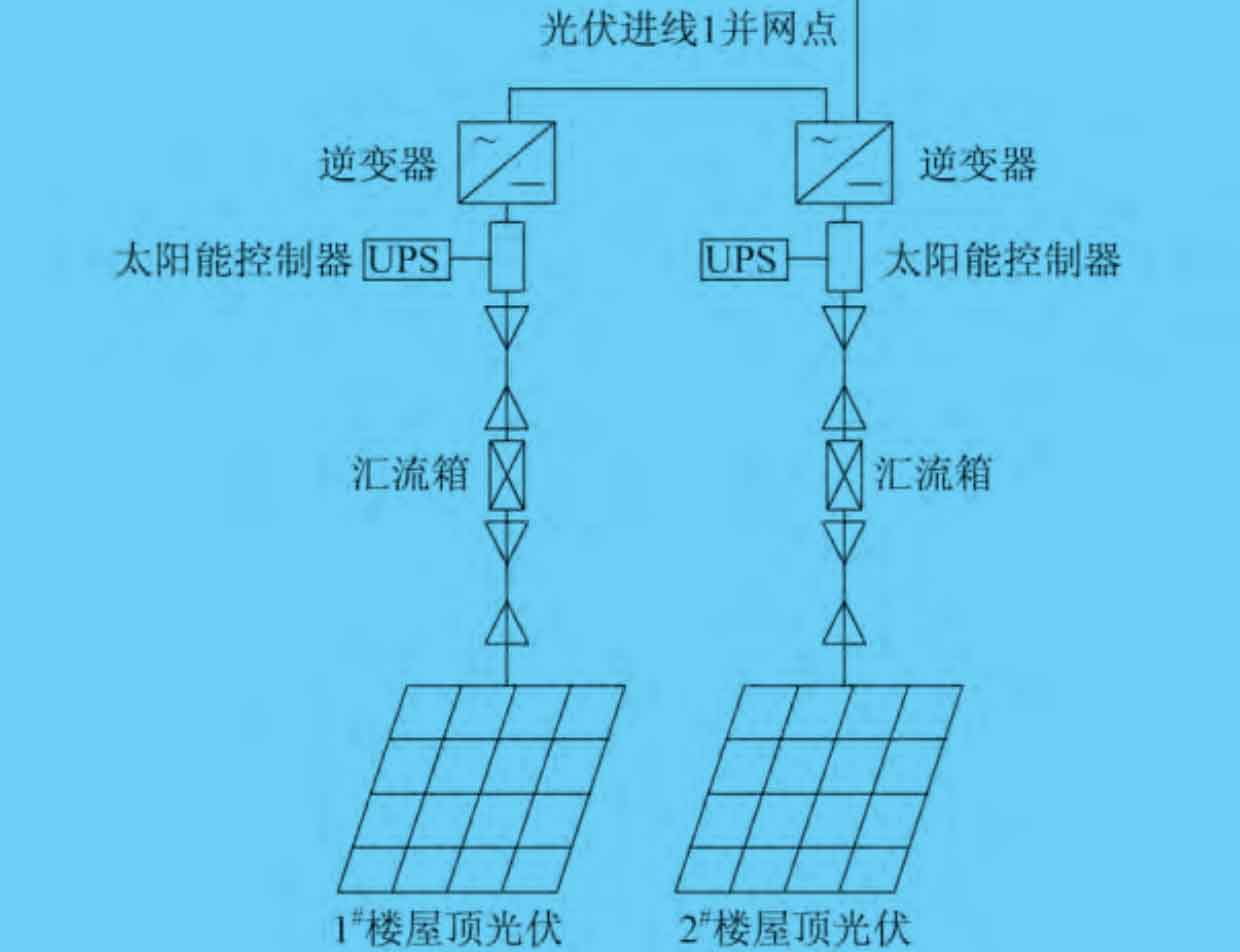
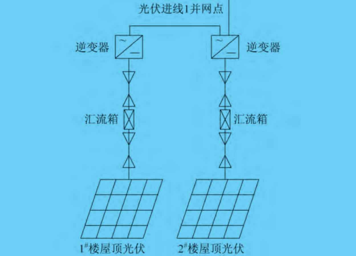
Solar controllers are often used in systems that use batteries, automatically controlling the entire photovoltaic and battery system, and providing overcharging and discharging protection for the battery. At present, MPPT solar controllers are mostly used, so if there is no battery set, there is no need for a controller to directly connect to the grid for power generation. The system diagram for setting up a solar controller is shown in Figure 1. The schematic diagram of the system without a solar controller is shown in Figure 2.
1.6 Step-up Transformer
Used for grid connection of 10 kV (or 35 kV) in photovoltaic power generation, photovoltaic systems in civil buildings are not commonly used. It mainly refers to the conversion of photovoltaic energy from large photovoltaic power plants into AC 380 V photovoltaic energy through inverters. The collected AC 380 V photovoltaic energy is locally boosted and then transmitted to the ring grid cabinet through a 10 kV cable line. It is collected by the ring grid cabinet and then transmitted to the 10 kV transmission line, and then transmitted to the 10 kV side busbar of the substation through a 10 kV transmission line, Then send it back to the public power grid for use. The transformer capacity can be selected based on the maximum output power of the photovoltaic array unit module. The system diagram for setting up a step-up transformer is shown in Figure 3.
1.7 Anti backflow device
Install an anti reverse current relay in the AC distribution box to monitor the power of the grid connection point. When reverse power occurs, cut off the photovoltaic inverter power generation circuit. Due to the function of the relay, a contactor needs to be set on the main circuit to complete the control function.
2. Information to be understood before designing photovoltaic power generation
(1) Which monomers are suitable for designing photovoltaic power generation devices.
① Due to the specific usage functions of buildings, such as boiler rooms, heat exchange stations, pressure regulating stations, refrigeration rooms, and outdoor power transformation and distribution rooms, their roofs are often equipped with equipment or have high safety levels, making them unsuitable for arranging rooftop photovoltaic power generation systems.
② Other buildings such as duty rooms and guard rooms have small roof areas, and it is not economical or suitable to install rooftop photovoltaic power generation systems.
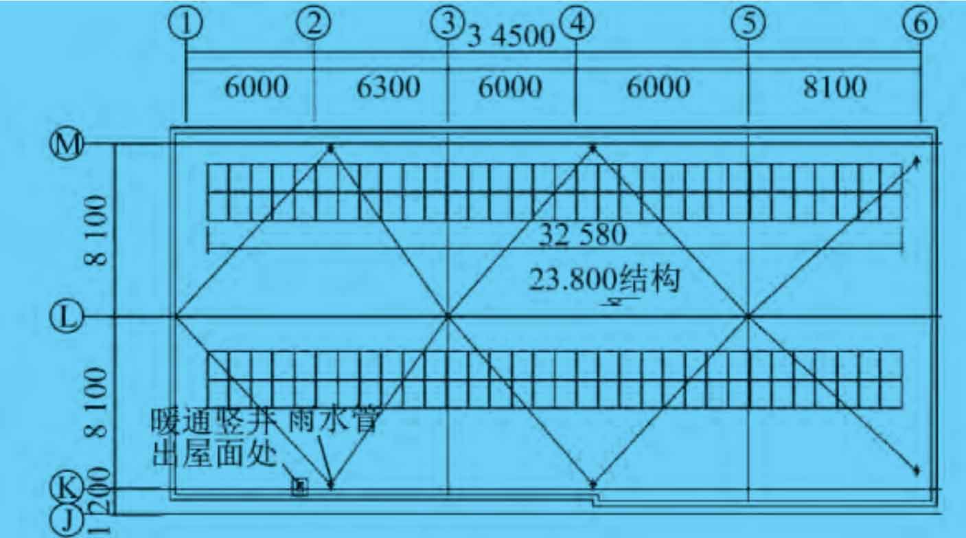
③ Due to the large area of production plants, office complex buildings, large commercial roofs, and residential buildings, it is possible to consider installing photovoltaic power generation systems on the roofs. The layout diagram of photovoltaic solar energy on the roof of the office building is shown in Figure 4.
(2) The geographical status of domestic photovoltaic power generation
The solar radiation in the south and north decreases month by month with the decrease of solar altitude angle and the shortening of day length. Therefore, December is the lowest value of the year. Among the four seasons, the solar radiation is the highest in summer (June August), the lowest in winter (December February), slightly smaller in spring (March May) than in summer, and between winter and summer in autumn. Therefore, the summer parameter is generally selected as the maximum value for photovoltaic calculation.
(3) Before system design
it is necessary to understand the customer’s needs, such as the daily load of photovoltaic energy, to determine the number of solar panels, and the nature of the load, including AC or DC, to determine whether an inverter is needed; Based on the requirements of Party A and the surrounding electricity situation, compare the use of electricity or batteries as backup power, and determine whether to install a solar controller to achieve the goal of reducing system costs; Whether to connect to the grid for use to determine whether to install anti backflow devices; Based on the current situation of the project, determine whether it is necessary to set up a separate lightning arrester or use the building’s own lightning protection lightning strip, whether to set up an independent grounding device, or use a public building grounding system, etc.
(4) Selection of voltage level for photovoltaic power generation connection.
① When the installed capacity of a single grid connection point is between 300 kW and 1 MW, it is recommended to use a 10 kV step-up transformer for connection, which is mostly used in small power stations and is dedicated to power generation. When local public grid conditions allow, 380 V connection can also be used (the high voltage level can also reach 35 kV).
② When the installed capacity of a single parallel network point is below 8-300 kW, it is recommended to use 380 V connection, and connect 380 V to the user’s distribution box, distribution room, or transformer low-voltage busbar at one or more points.
③ When the installed capacity of a single parallel network point is 8 kW or less, single-phase connection can be used, and one or more points can be connected to the user’s distribution box or room.
3. Common calculations for photovoltaic systems
(1) Estimate based on electricity demand
The total power of the solar cell module P=(consumer power × Electricity usage time/local peak sunshine hours) × Loss coefficient. If the construction party requires 50 kW of electricity, with a power consumption time of 8 hours, local peak sunshine hours (summer) of 4 hours, and a loss coefficient of 0.8, then P=80 kW. If the engineering battery module uses a combination of 180 Wp monocrystalline silicon battery module and 55 Wp thin film module (photovoltaic power generation commonly uses multiple principle modules for mixed installation to improve the efficiency of photovoltaic power generation), then N=80000/(180+55) ≈ 340 pieces.
(2) Calculation of photovoltaic array power generation
Annual power generation (kWh)=local total annual radiation energy × Photovoltaic array area (m2) × The comprehensive correction coefficient K of the battery module, K=K1K2K3K4K5, where K1 is the correction coefficient for long-term operational performance degradation of the solar cell, generally taken as 0.8; K2 is the correction factor for the decrease in component power caused by dust blocking glass and temperature rise, taken as 0.82; K3 is the line loss correction coefficient, taken as 0.95; K4 is the efficiency of the inverter, usually taken as 0.85, which can also be determined based on the technical parameters provided by the inverter manufacturer; K5 is the correction coefficient for the orientation and tilt angle of the photovoltaic array. Beijing is located between 39 ° and 41 ° north latitude. According to Appendix A of GB50797-2012 “Design Code for Photovoltaic Power Stations”, the maximum radiation amount is in June, with an annual total radiation energy of 33.7. If 50 is used × 12=600 photovoltaic modules, each with an area of 1 × 1.6=1.6 m2, then the photovoltaic array area is 960 m2, and it is recommended to use a comprehensive correction coefficient of 0.5 for the battery components, resulting in an annual power generation of 33.7 × nine hundred and sixty × 0.5=16 176 kWh.
(3) The capacity of the battery (if any).
① The total capacity of the battery C=DFP0/UK, where D is the maximum number of hours without sunlight; F is the battery discharge correction coefficient, select 1.05; P0 is the average load capacity; U is the discharge depth, taking 0.5-0.8; K is the inverter loss rate, taking 0.7 to 0.8. It is generally believed that the Beijing area works 4 hours a day in winter and 5.5 hours a day in summer. Due to the high demand for batteries, the selection is based on the summer situation. If the electricity demand of the construction party is still P0=50 kW, to meet the working usage of 5.5 hours a day, C=5.5 × 1.05 × 50/(0.5 × 0.7)=825 kWh.
② Determination of the number of batteries in series and parallel. The number of batteries connected in series=voltage level/voltage of a single battery. If a single battery is 2 V, then 24 V/2 V=12 pieces, forming a string; The number of parallel connections=total required volt amperes/ampere hours of a single battery. For example, if the voltage level is 24 V, 825 000/24=34 375 Ah. If a product with a single battery ampere hour of 400 Ah is selected, 34 375/400 ≈ 86 circuits will be connected in parallel.
(4) The specification requires
The DC current component injected into the public connection point by the photovoltaic power generation system should not exceed 0.5% of its AC rated value.
(5) According to regulations and the requirements of the State Grid
The power factor of photovoltaic power generation systems connected to the grid through a voltage level of 10 kV should be within the range of leading 0.98 and lagging 0.98, and continuously adjustable to meet the dynamic power factor changes of the line.
(6) According to the provisions of GB/T 12325-2008 “Power Quality Supply Voltage Deviation”
The deviation of three-phase supply voltage for 10kV and below is ± 7% of the nominal voltage, and the deviation of single-phase supply voltage for 220V is+7% and -10% of the nominal voltage.
4. Photovoltaic System Design
The basic principles of photovoltaic system design are as follows:
(1) Based on the installed capacity requirements provided by Party A and taking into account the operation mode, reasonably determine the voltage level and mode of connection.
(2) Use the corresponding photovoltaic design system diagram.
(3) Represents the selection requirements for electrical equipment.
(4) Represents the requirements for electrical relay protection.
(5) Draw photovoltaic floor plans and detailed drawings, etc.
4.1 Design of photovoltaic cell modules
(1) The optimal angle and installation method of photovoltaic cells. Calculate the solar radiation on the inclined plane, and the installation angle of the battery array has a significant impact on the efficiency of the photovoltaic power generation system. For fixed battery arrays, the optimal inclination angle is the inclination angle at which the photovoltaic system generates maximum electricity throughout the year. It is recommended that the battery components on the roofs of civil buildings be installed in a fixed bracket with the optimal inclination angle calculated by professionals. Compared to the tracking bracket, the utilization rate of light is slightly lower. However, compared to the inconvenience of later maintenance and repair of the tracking bracket, the fixed bracket has a relatively higher cost-effectiveness, There is basically no maintenance required, which saves space and is suitable for limited areas such as roofs.
(2) Determination of the number of photovoltaic modules in series and parallel. It is necessary to consider backwards from the power consumption side. As the maximum power point tracking (MPPT) voltage of the inverter is approximately 0.7~0.8 of the open circuit voltage of the photovoltaic panel, if Party A requires a 50 kW power generation, a 50 kW inverter can be used, with an MPPT range of DC 450~780 V and a maximum allowable input voltage of DC 800 V. The maximum value of the series connected component is equal to the maximum allowable input voltage/component open circuit voltage Uoc, Uoc=37.5 V (this value is usually used for optical voltage), and the maximum value of the series connection component is 800/37.5 ≈ 21, so the maximum number cannot exceed 21; The minimum value of the series connection component=minimum allowable input voltage/optimal working voltage. The minimum allowable input voltage of the MPPT is DC 450 V, and the optimal working voltage of the battery component is DC 30.4 V. Therefore, the minimum value of the series connection component is 450/30.4 ≈ 15. Therefore, it is reasonable to choose a combiner box (if there is no DC distribution box for merging, directly enter the MPPT), but in order to simplify wiring and reduce construction complexity, It is recommended to use a series connection method of 3-4 sets in series and 1 circuit in parallel. The photovoltaic module can be designed according to the principle of 6 sets in series and 3 sets in parallel connected to the combiner box.
4.2 Design of combiner box
The schematic diagram of the combiner box system is shown in Figure 5.
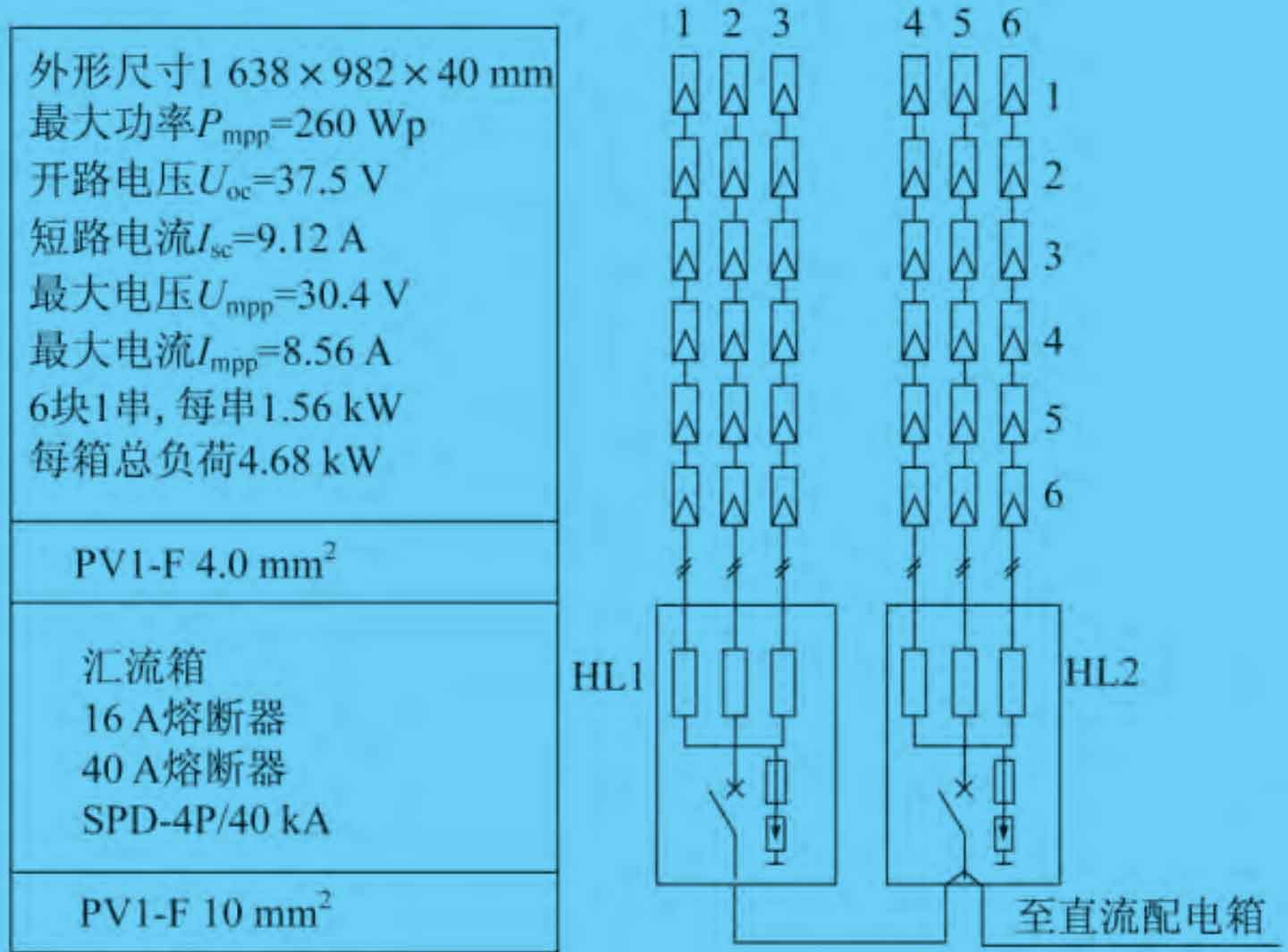
The combiner box should be designed with a single fuse for overall protection of the DC circuit breaker to prevent lightning current from invading the surge protector.
(1) Fuse selection: It is required that the fuse In ≥ 1.56 Isc, where Isc is the short circuit current of the battery pack, as shown in Figure 5 parameter. The fuse In ≥ 1.56 × 9.12=14.2 A, a fuse of 16 A can be selected.
(2) If one combiner box is set for every three strings in the project, the power P=1.56 × 3=4.68 kWp, it is required that the sensitivity coefficient of the circuit breaker action at the fault point should be greater than 1.25. Therefore, the rated current of the DC circuit breaker should be selected based on In ≥ 1.25Isc, indicating that the rated current of the circuit breaker In ≥ 3 × 1.25 × If 9.12 A=34.2 A, it is recommended to select the main switch of the combiner box with In=40 A. The combiner box needs to be equipped with a surge protector: it can be classified as C-level 8/20 μ Consider designing the waveform, such as a nominal discharge current Iimp=15 kA and a maximum discharge current max=40 kA. The selection of cables and wires is based on the calculated current, but photovoltaic dedicated cables need to be selected.
4.3 Design of DC distribution box
The DC distribution cabinet mainly connects the DC cables output from the combiner box to the grid connected inverter, and sets them according to the size of the photovoltaic system. It is similar to the design of the AC system, but the transmission is opposite. The AC system is a secondary distribution, and the DC system is a secondary combination. This distribution cabinet includes a DC input circuit breaker (protecting the superior cables), a photovoltaic surge protector (both in the LPZL area, but not recommended when the distance from the combiner box or AC distribution box is ≥ 10 meters), and an anti backflow diode (if the combiner box is set, it is not recommended to set it repeatedly). In the above example, a total of 60 photovoltaic modules are divided into 10 combiner box circuits and enter the DC distribution box for secondary closing. The DC distribution box is equipped with a branch circuit breaker and a main circuit breaker, which are then connected to the inverter. The schematic diagram of the DC distribution box system is shown in Figure 6.
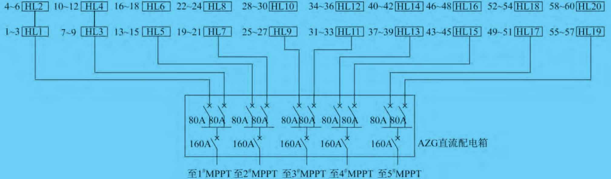
4.4 Design of inverters
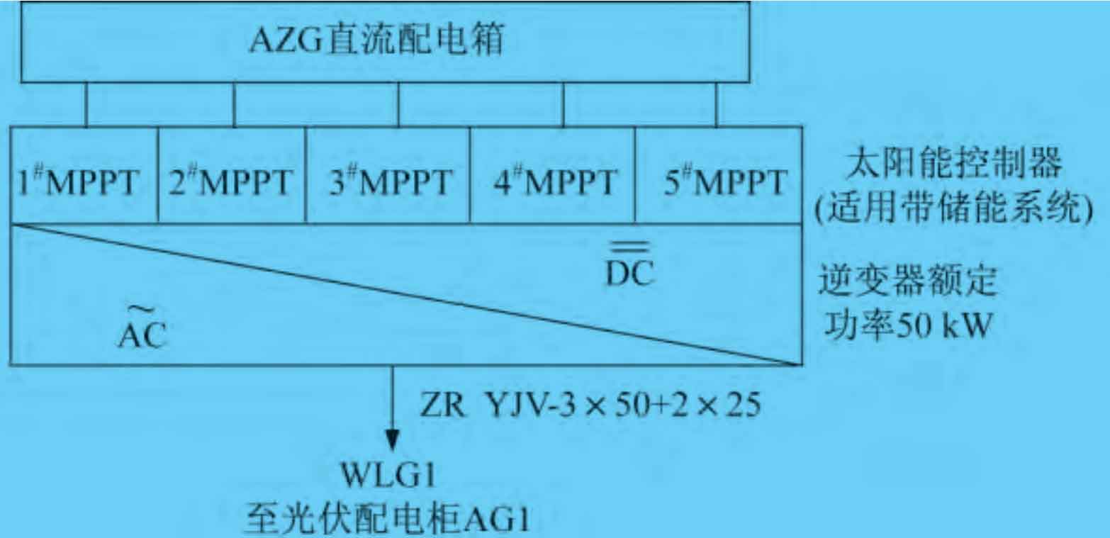
The inverter room is an important part of the entire power plant. The direct current generated by solar panels is converted into 380 V AC power through the indoor inverter and sent to the power grid. The core requirement of the inverter is to achieve synchronous grid connection of photovoltaic power generation without impact, ensuring that the system output is at the same frequency, phase, and amplitude as the power grid. If a system is equipped with a solar controller, the inverter box is divided into two parts: MPPT and inverter. MPPT is a solar controller that can detect the generation voltage of photovoltaic modules in real time, select the highest voltage and current value for charging and discharging. Based on the monitoring function of photovoltaic modules, it is still recommended to use MPPT for systems without batteries. 1-3 kW photovoltaic modules can be designed as single circuit MPPT, and 3-30 kW photovoltaic modules can be double circuit MPPT. The inverter system design is shown in Figures 7 and 8. The system uses two MTTP channels, with a 50 kW inverter product size of 800 mm × 600 mm × 2060 mm, AC distribution cabinet and inverter are installed in the inverter room. Due to the small power generation scale of civil buildings, it is recommended to equip each photovoltaic power generation unit with one set of series inverters. Each building should choose a suitable inverter based on the actual installation capacity that can be arranged. The series inverters are recommended to be arranged on the roof of the building, near the parapet wall, or in the electrical shaft.
4.5 Design of AC distribution box
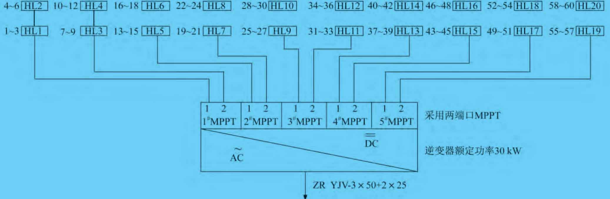
The AC distribution box achieves grid connection between the photovoltaic power generation side and the power grid. Due to the integration of the low-voltage busbar in the next step, it can be installed in the transformation and distribution room. It is recommended to choose a distribution cabinet with an isolation transformer to ensure the isolation between the photovoltaic side and the power grid side; Set the meter (if the method and position of the meter cannot be determined, the meter position should also be reserved); Surge protectors (also requiring a distance of more than 10 meters from the surge protectors of the upper and lower levels); If there is an anti backflow device and system monitoring, a contactor for collecting signals should be installed to be used in conjunction with the anti backflow controller and monitoring module. The schematic diagram of the three-phase AC grid connected cabinet is shown in Figure 9.
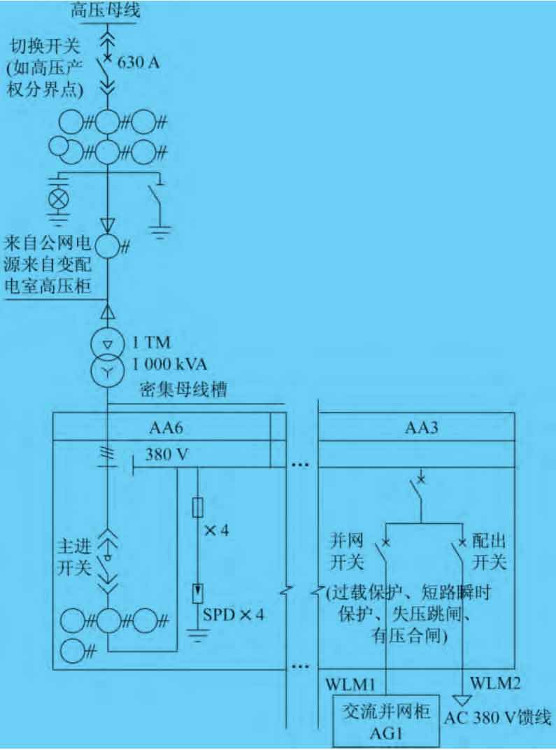
4.6 Requirements for photovoltaic power generation relay protection
(1) When distributed photovoltaic power generation is connected to the public power grid at a voltage level of AC 380 V, the circuit breakers at the connection point and public connection point should have functions such as overload protection, short-circuit instantaneous protection, shunt tripping, voltage loss tripping (after voltage loss, the circuit needs to be restarted before it can run again), voltage blocking and closing (without secondary operating power supply, power cannot be transmitted without protection), etc. AC 380 V grid connected system
The schematic diagram of integrated protection is shown in Figure 10.
(2) When the photovoltaic power generation dedicated line is connected to the user’s 10 kV bus, generally three section protection can be configured on one side of the low-voltage side of the substation. If there are special requirements, if three section protection cannot be achieved, it is common to configure longitudinal current differential protection in booster substations or collection stations with two or more booster transformers, and overcurrent protection can be used as its backup protection.
4.7 Measurement of photovoltaic power stations
The energy metering point of photovoltaic power stations should be set at the property boundary between the power station and the power grid facilities or at the location specified in the contract agreement. Civil building photovoltaic power stations should use dedicated metering.
(1) In a 10 kV grid connected system, the accuracy of the voltage transformer and current transformer of the electrical energy metering device is 0.2 seconds, and the accuracy of the gateway metering device is generally no less than Class II electrical energy metering device.
(2) In a 380/220 V grid connected system, the gateway metering device generally selects an energy metering device of no less than Class III, and the energy metering device uses an accuracy of 0.5 s voltage transformer and 0.5 s current transformer.
(3) Configure a 0.2 s level metering meter, select an intelligent energy meter, and maintain communication with the computer monitoring system.
4.8 Monitoring of photovoltaic systems
The data collector is set up at the inverter and AC distribution cabinet to collect and record operating data. The AC distribution box is connected through contactor signals, and the inverter is directly equipped with an RS-485 signal acquisition interface to collect meteorological data such as solar radiation, electrical performance parameters, equipment working status, and perform related control operations, such as switching the inverter output, outputting the solar cell array, and tracking control, It can also include anti reflux function.
5. Plane Design of Photovoltaic Systems
(1) Electrical connection of photovoltaic modules:
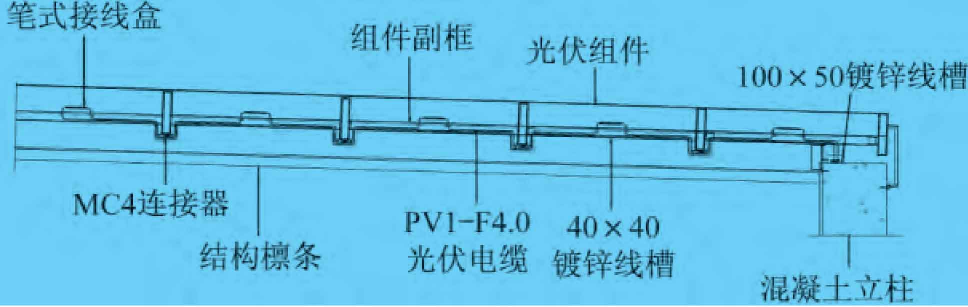
The reserved length of the outgoing line for the photovoltaic module configuration can be 850 mm, and the wiring adopts a back connected pen type junction box. Its main function is to export the electrical energy generated by the solar cell module through the cable. A bypass diode is installed inside the photovoltaic junction box to prevent hot spot effects. Photovoltaic connectors are the connecting devices between photovoltaic modules, and MC4 type is currently commonly used. The schematic diagram of building photovoltaic power generation section is shown in Figure 11.
(2) Cable laying.
① The direct current generated by the battery panel causes electric arcs to generate sparks, and the failure of insulation materials can also cause electric sparks, which usually occur at cable joints. Therefore, flame-retardant and fire-resistant cross-linked polyethylene insulated power cables are selected for roof cables. Therefore, ZRC grade flame-retardant cables can be used for AC high/low voltage power and control cables in photovoltaic systems, while fire-resistant cables are used for important cables such as firefighting, DC cables can use PV1-F copper core cables.
② Due to extreme weather conditions such as extreme heat, in order to prevent insulation material failure caused by cable aging, cables between photovoltaic modules and between modules and combiner boxes should have fixed and sun protection measures to provide shade or protection.
③ It is recommended to run a single cable on the roof through a conduit, and bundle cables should be protected using cable trays.
④ The photovoltaic components of the rooftop photovoltaic field to the string combiner box cables are mainly laid in an open manner along the bracket, with cable trays and boxes laid in an open manner along the exterior wall to the ground. They are directly buried and laid to the system’s power transformation and distribution equipment, and the reserved pipelines of existing cable trenches are used as much as possible along the way.
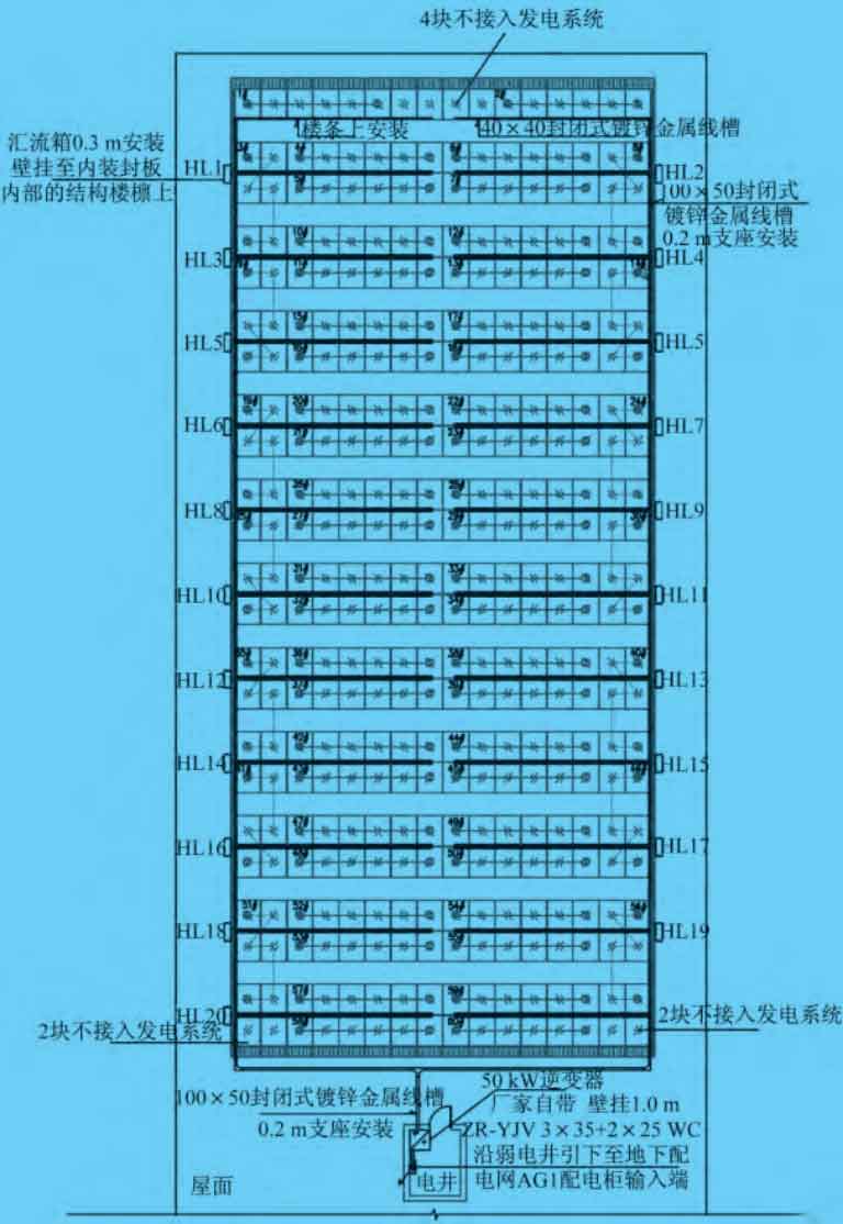
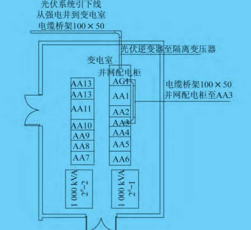
⑤ If the photovoltaic power station is close to the substation, the entire line from the photovoltaic power station to the substation can use a 10 kV cable line (directly buried), without the need for overhead lines. The connecting cables between components and strings are routed through trunking, and the schematic diagram of photovoltaic power generation on the building roof is shown in Figure 12. The plan diagram of the building photovoltaic power generation and distribution room is shown in Figure 13.
(3) Lightning protection and grounding.
Lightning protection can be achieved by utilizing the existing lightning strip on the roof and parapet wall. Therefore, lightning rods and wires can no longer be installed repeatedly in the photovoltaic array to prevent direct lightning strikes. Grounding within the photovoltaic site -40 mm × 4mm galvanized flat steel connects the photovoltaic field equipment brackets reliably, and connects the down lead along the wall or structure support to the main grounding grid in the station. The insulation coordination and overvoltage protection of photovoltaic outdoor distribution devices are considered based on the pollution level of outdoor distribution devices (for heavily polluted situations), and the leakage distance of the external insulation of distribution devices is considered as ≥ 2.5 cm/kV.
(4) Fire alarm.
The fire alarm is composed of linear fiber optic temperature sensing fire detectors, temperature sensing optical cables, temperature measurement software, cabinets, power supplies, installation accessories, and other auxiliary equipment, mainly used for overtemperature alarm of photovoltaic cables.
6. Conclusion
Mainly focusing on the use of roofs or other open spaces for photovoltaic power generation in civil buildings, this article introduces the composition of photovoltaic power generation systems, analyzes the situations that need to be understood before photovoltaic power generation design, and expresses the most basic design knowledge in photovoltaic electrical engineering. It is described using the expression method of electrical construction drawing design, so that electrical designers can have a comparative understanding of photovoltaic construction drawings and the design in the deepening stage.