
Energy storage methods include flywheel energy storage, potential energy storage, battery energy storage, thermal energy storage, etc. Due to the advantages of high specific energy, high average discharge voltage, low self discharge rate, no memory effect, high charge discharge capacity conversion efficiency, long cycle life, wide working temperature, and environmental friendliness, lithium-ion batteries have developed into the most common energy storage technology in just over 20 years. From electronic products that can be seen everywhere in daily life From new energy vehicles to the increasingly growing wind and solar power storage power stations. Based on the high reliability, long lifespan, and high environmental temperature requirements of the project, high-power lithium iron phosphate batteries with high maturity, good high-temperature characteristics, and high safety were adopted. Combined with efficient active balancing battery management technology, a power supply with high output power, long output time, good safety, maintenance, and guarantee was designed and manufactured. Its reliability was verified in long-term application in actual high-temperature environments.
1. High power energy storage power supply system
1.1 System composition
To meet the requirements for rapid maintenance of high-power power supply systems, the system adopts a modular design method, with the weight of any module not exceeding 60 kg.
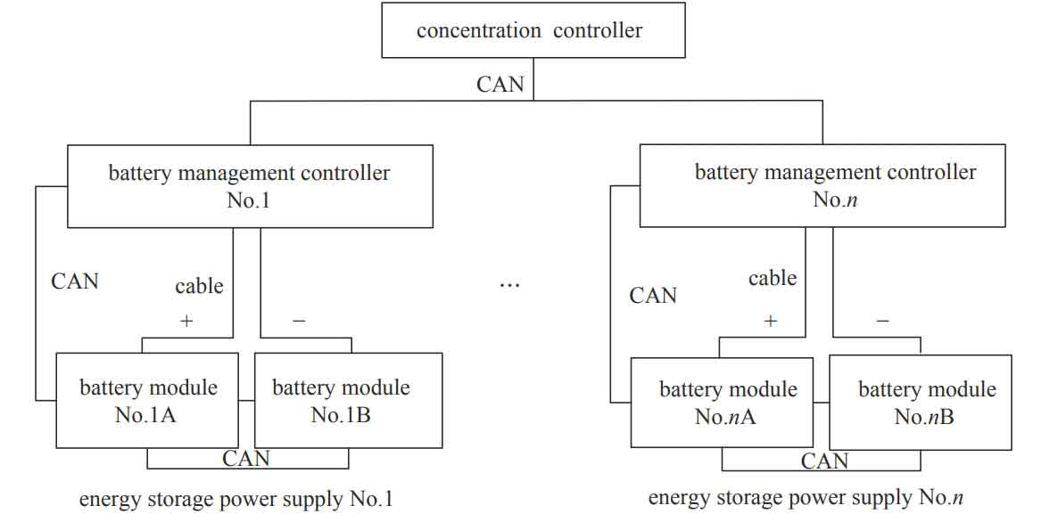
The high-power lithium battery energy storage battery system is shown in Figure 1. The high-power energy storage battery system is managed by the centralized control box of the energy storage battery. A set of energy storage battery centralized control boxes manages multiple high-power energy storage power sources to meet the different requirements of the vehicle system for total power.
Each high-power energy storage power supply consists of three chassis, including battery pack A, battery pack B, and a battery management main controller. Battery pack A and battery pack B are used in series. A battery cell voltage and temperature acquisition board is installed in battery packs A and B, and an efficient active equalizer is integrated. The temperature and individual battery data collected by the battery collection board are uploaded to the battery management main controller through the CAN bus, and receive commands from the battery management controller to balance and manage the individual battery. The battery management control box is equipped with a battery management control module, charge and discharge relay, charging fuse, and water-cooled charger.
1.2 Energy storage power supply
1.2.1 Electrical design
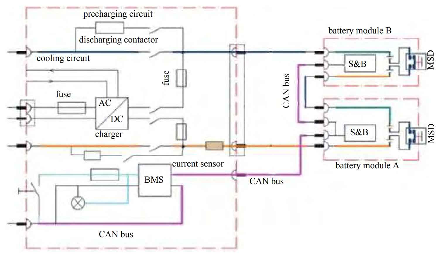
Taking into account the demanding requirements of high-power energy storage power supply power demand, maximum/low voltage limits, usage environment, maintenance, and cycle life, a 40 kW energy storage power supply consists of two 20 kW battery packs in series. Due to the high discharge rate of the battery design, and considering requirements such as cycle times and service life, the discharge depth of the battery pack is designed to be 55%, and the capacity requirement of the battery pack is about 16 A · h, The scheme of using 8 A · h monomer 2 parallel (16 A · h) 42 series battery pack can meet the demand of lithium battery energy storage power supply. The electrical design of the energy storage power supply is shown in Figure 2. Technical indicators of energy storage power supply: capacity of 16 A · h; Voltage range: 210-330 V; Maximum output power of 40 kW; Discharge time of 200 s; Energy storage: 4.3 kW · h.
1.2.2 High power battery cells
The safety of lithium-ion batteries has received widespread attention. Due to its good safety, no heavy metal pollution, good economy, and long service life, lithium iron phosphate battery cells are one of the main batteries for the development of new energy vehicles and energy storage equipment. Therefore, in the coming decades, a large number of manufacturers will invest in research and development and process improvement, and the quality can steadily improve.
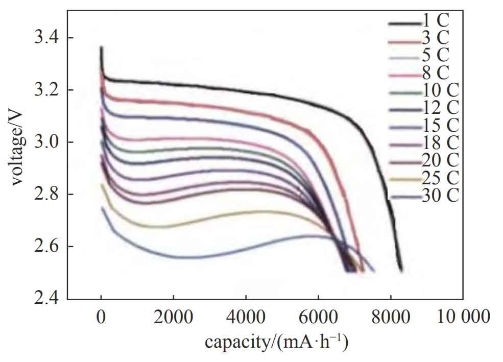
Considering the requirements of project progress and reliability, it is necessary to choose standardized battery cells that have been widely used. According to the design, a capacity of 8 A · h square aluminum shell battery cell, model IFP1780123PB lithium iron phosphate battery cell, has been standardized for 8 years. The electrodes are connected by bolts, with an annual production capacity of about 80000 units, exported to Australia and other places. The main performance parameters are shown in Table 1. The discharge curve of the battery cell is shown in Figure 3. Under the discharge condition of 30 ° C, the battery cell can still release a capacity of 7.5 A · h or more, demonstrating good power characteristics.
| No. | Name | Parameter |
| 1 | Capacity | 8 A·h |
| 2 | Voltage | 3.2 V |
| 3 | Opening voltage | 3.2~3.4 V |
| 4 | Resistance | ≤1.3 mΩ |
| 5 | Weight | (0.32±0.02) kg |
| 6 | Charging cutting voltage | 3.65 V |
| 7 | Operation temperature | Charging: 0~50 ℃; Discharging: −20~60 ℃ |
| 8 | Restore temperature | −20~60 ℃ |
| 9 | Maximum continuum charginge current | 3 C |
| 10 | Discharging cutoff voltage | 2.5 V |
| 11 | Maximum continuous discharginge current | ≥10 C |
| 12 | Discharging pulse current/time | 700 A/3.5 s |
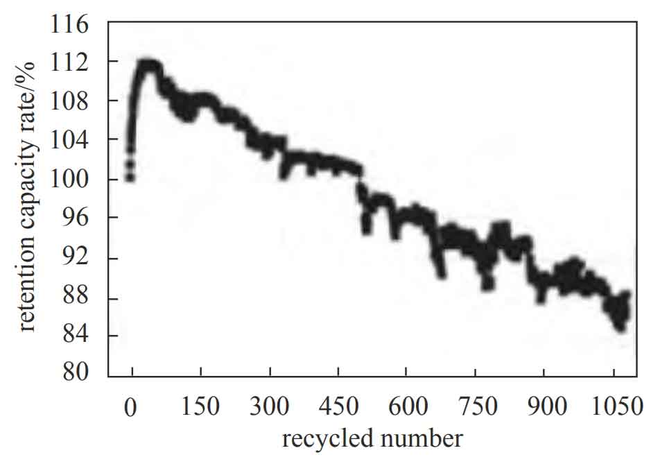
In order to meet the requirement of 1000 cycles over 5 years, the cycling performance of the battery cells was studied, as shown in Figure 4. After 1050 cycles of 3 ° C strict charging and 5 ° C discharge (100% DOD), the capacity retention rate was above 85%. In actual working conditions, the maximum discharge depth was about 55%, and it is expected that the battery pack can meet the requirement of 1000 cycles over 5 years.
1.2.3 Thermal design and testing
Firstly, the working process of the energy storage power supply was analyzed. The most severe process was to store it for 4 hours under the initial state of charge of 60% and ambient temperature of 60 ℃. Then, it was cooled with 5 L/min of antifreeze for 15 minutes, then charged for 15 minutes, then discharged for 200 seconds, then charged for 30 minutes, then discharged for 200 seconds, and cycled more than 4 times.
Then, the power consumption of the battery cells under operating conditions was tested as input conditions for thermal simulation of the energy storage battery pack. The simulation results are shown in Figure 5.
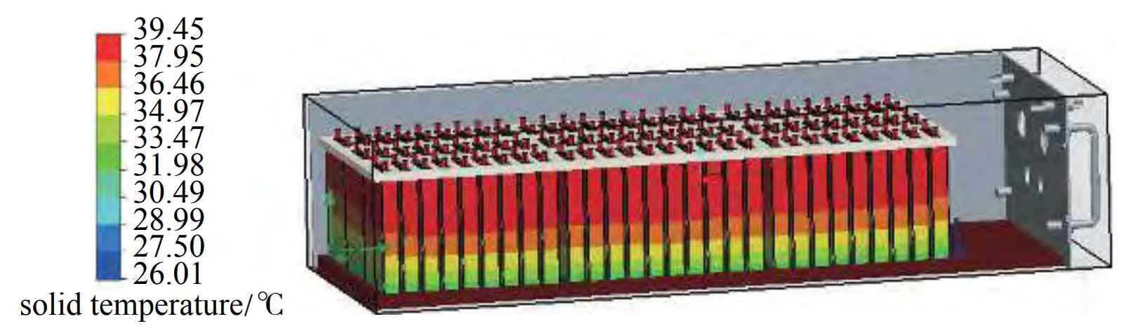
The simulation results show that during the discharge and charging cycle, the maximum temperature of the battery occurs at the completion of the first discharge, with a maximum temperature of 44.1 ℃. After the completion of the second battery charging, the maximum temperature of the battery is 39.5 ℃, which is lower than the highest temperature of the first battery discharge. After repeated cycles, the high temperature point stabilizes at 35 ℃ and the low temperature point stabilizes at 31 ℃, meeting the optimal working temperature range of the battery cell.
The experiment was conducted under the strictest working conditions. After the first discharge, the maximum temperature was 45 ℃, and after the second charging, the maximum temperature was 40 ℃, meeting the requirement of a maximum safe working temperature of 50 ℃ for the battery cell; Then repeat the cycle repeatedly, and the temperature stabilizes between 30-35 ℃, meeting the optimal working temperature range of the battery cell.
1.2.4 Sampling, balancing, and management control of batteries
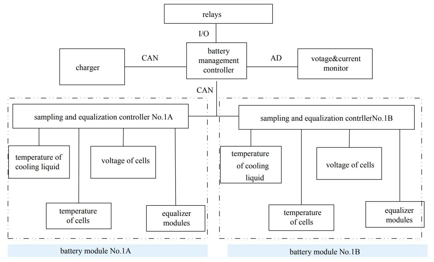
In the battery pack, a battery sampling and balancing module is installed, and a battery management main controller is installed in the battery management main controller chassis. The functional block diagram is shown in Figure 6.
Battery sampling and balancing module: Each battery pack sampling includes 2 water inlet temperature sensors and 16 battery cell temperature sensors, which monitor the water temperature and battery cell temperature. The battery sampling and balancing module also collects the voltage of each battery cell, and the data is fed back to the battery management main controller through the CAN bus.
The battery management main controller determines whether the energy storage battery is in a normal state through a threshold, which includes: the lower limit of the water inlet temperature is 5 ℃ and the upper limit is 45 ℃; The lower limit of the battery cell temperature threshold is 0 ℃, and the upper limit is 50 ℃; The maximum temperature difference is 10 ℃; The lower limit of individual voltage is 2.5 V, and the upper limit is 3.65 V; Battery cell voltage difference of 50 mV for balanced start-up.
The battery management main controller mainly includes the following functions:
1) Monitor the charging or discharging current of the energy storage power supply, and calculate the battery’s state of charge through integration;
2) Monitor the total voltage of the entire set and determine the status of the entire set of batteries by combining the total voltage with the collection module to return the voltage of individual batteries;
3) Upload temperature, individual voltage, voltage difference and other data through the CAN bus, and determine the status of the energy storage power supply through a threshold. Based on the voltage difference, issue a battery balancing command to the sampling and balancing module;
4) Check if the battery sampling and balancing module is online;
5) Calculate the leakage current based on the voltage output from the positive and negative electrodes of the energy storage battery pack.
6) Upload status information such as temperature, battery cell voltage, total voltage and current, and leakage current to the centralized controller of the energy storage power supply.
7) Control the charging and discharging operations according to the instructions issued by the central controller.
1.2.5 Charger
To improve the electromagnetic compatibility of the system, the charger adopts power factor correction technology, with a power factor of 0.99 and current harmonics less than 3%. It can adapt to input voltages of 95VAC-265VAC, with a maximum output voltage of 330 V, a maximum output current of 20 A, and a maximum power of 6.6 kW. The charger is equipped with a built-in thermal sensing device, which has an overheat protection function and can automatically recover. Fully sealed sealing process, with a protection level of up to IP67.
2 Engineering testing
2.1 Transportation safety test
Due to the safety management requirements of lithium-ion batteries for sea/air transportation, battery cells and battery packs need to meet the testing requirements of Section 38.3 of Part 3 of the Recommendations for the Transport of Dangerous Goods – Testing and Standards Manual, which includes a total of 5 environmental tests and 3 electrical safety tests [17-18]. Based on the above requirements, the first selected battery cell has been tested and certified; The structural design of the battery pack meets the requirements for large battery packs weighing 12 kg or more: 50gn/11 ms impact and vibration requirements. Vibration experiment method: In three mutually perpendicular directions, perform a logarithmic scan from 7 Hz to 200 Hz and return to a sinusoidal waveform vibration at 7 Hz. Each cycle lasts for 15 minutes and is conducted 12 times, with 3 hours in each direction.
After the product development was completed, a preliminary test was conducted to evaluate that it met the requirements; Then, samples will be taken from the first batch of finalized products for third-party testing and certificates will be obtained.
2.2 General Quality Testing and Evaluation
2.2.1 Reliability indicators
For example, the energy storage power supply system uses 7 energy storage power supplies, including 1 centralized controller, 7 battery management main controllers, and 14 battery packs.
1) Centralized controller
According to the basic data and methods of the GJB/Z 299C reliability prediction manual, the MTBF index of the centralized controller is calculated, and the failure rate of the centralized control box is 1.42 × 10⁻⁵ hours, which means the MTBF is 70400 hours.
2) Battery management main controller
According to the specifications of the on-board charger, the MTBF is 150000 hours, and one unit is used; The battery management unit (BMU) has an MTBF of 500000 hours; 4 relays with a failure efficiency of 1.0 × 10 − 7/h; Two insurance units are used, with a failure rate of 1.00 × 10 − 7/h; Six connectors are used, with a calculated failure rate of 0.4 × 10 − 6/h. According to the basic model of failure rate, the failure rate of the battery management main controller is 7.86 × 10 − 6/h, MTBF is 127200 h.
3) Battery pack
In the battery pack, the sampling and balancing unit of the battery has a failure efficiency of 1.0 × 10 − 7/h, using a quantity of 4; The failure rate of individual battery cells ranges from 10-7 to 10-8/h. The battery cells used in this project have undergone extensive vehicle validation and strict consistency screening, ensuring a single cell failure rate of 0.8 × Below 10-7/h, each battery pack uses 84 batteries; The failure rate of insurance is 1.00 × 10 − 7/h, using a quantity of 2; The number of connectors used is 4, and the calculated failure rate is 0.25 × 10 − 6/h; Temperature sensor, failure rate 1.00 × 10 − 8/h, 16 temperature sensors are used. Calculate the failure rate of the energy storage battery pack as 8.37 × 10 − 6/h, which means the MTBF is 119 500 h.
4) Basic reliability
Calculate the basic reliability of the energy storage power supply system, as shown in Table 2. The failure rate of the energy storage power supply system is 1.84 × 10 − 4/h, MTBF is 5400 h.
| No. | Component name | Failure rate/h^−1 | Number | Total failure rate/h^−1 |
| 1 | Concentration controller | 1.42×10^−5 | 1 | 1.84×10^−4 |
| 2 | Battery management controller | 7.86×10^−6 | 7 | 1.84×10^−4 |
| 3 | Battery module A | 8.37×10^−6 | 7 | 1.84×10^−4 |
| 4 | Battery module A | 8.37×10^−6 | 7 | 1.84×10^−4 |
5) Task reliability assessment
Completed 660 task reliability tests and met the validation of 0.985 (0.8 confidence) task reliability tests.
2.2.2 Maintainability
The energy storage battery unit adopts three types of modular designs: centralized control box, charging and high-voltage control box, and energy storage battery box. The volume and weight are shown in Table 3, and the boxes are all plug-in. The maintainability has been tested on site, and the average repair time (MTTR) at the grassroots level is not more than 30 minutes.
| No. | Module design | Number | Weight/kg | Size |
| 1 | Concentration controller | 1 | 25.6 | 482 mm×128 mm×593 mm |
| 2 | Battery management controller | 7 | 22.5 | 482 mm×85 mm×595 mm |
| 3 | Battery module | 14 | 54.0 | 327 mm×195 mm×750 mm |
2.2.3 Testability
Adopting a mature electric vehicle battery management system, conducting internal inspections of the system and reporting to the control system in real-time. On site, testing performance was assessed and the fault detection rate was 100%; Fault isolation to 1 LRU/LRM is 100%, fault isolation to 2 LRUs/LRMs is 100%, and fault isolation to 3 LRUs/LRMs is 100%; The detection false alarm rate is 0%.
2.2.4 Supportability
Statistics were conducted on the components/components used, and the results showed that they meet the guarantee requirements for the entire life cycle (10 years).
2.2.5 Security
This project uses an 8 A · h power type lithium iron phosphate battery, which has a wide temperature range (-20~75 ℃) and high temperature resistance. The peak electric heating of lithium iron phosphate can reach 350~500 ℃, making it less prone to thermal runaway. The individual and small modules have passed the certification of the National Motor Vehicle Quality and Technical Supervision and Inspection Center.
In terms of system design and production: 1) A specialized brake control scheme can ensure timely shutdown of energy storage power supply in emergency situations such as danger or malfunction, ensuring safety; 2) Equipped with a fuse, it quickly disconnects in the event of a short circuit to prevent the battery pack from being over discharged and to protect the backend equipment; 3) The insulation value of the battery pack’s resistance to ground is greater than 10 M Ω; 4) To ensure the safe operation of the battery, the battery management system monitors and protects against high individual voltage, low individual voltage, high temperature, low temperature, excessive charging current, and excessive discharge current; 5) Anti insertion measures have been taken for connectors and other components. Through the above measures, the safety of energy storage power supply is ensured, and instructions for precautions are provided to users.
2.2.6 Environmental adaptability
According to the environmental adaptability requirements of the national military standard, vibration, low-temperature storage, low-temperature operation, high-temperature storage, high-temperature operation, and humid heat tests were carried out during the identification stage; The delivered products underwent vibration, low-temperature storage, low-temperature operation, high-temperature storage, and high-temperature operation tests.
2.2.7 Electromagnetic compatibility
The 24V power supply module selected in the energy storage power supply system meets the requirements of EN55022 ClassB, EN6100-3-2 ClassA, and EN61000-3-3. The electromagnetic compatibility characteristics of the charger meet the requirements of Article 11.3.1 of GB/T18487.3-2001 for electromagnetic immunity; Electromagnetic disturbance meets the requirements of Article 11.3.2 of GB/T18487.3-2001; The harmonic current meets the requirements of GB 17625.1-2006.7.1.1. The battery management system is designed and produced by an electric vehicle component enterprise certified by the Road Vehicle Functional Safety Standard (ISO26262), and all products have passed industry standards and strict EMC testing. The cables used are all shielded, and the shielding layer is connected to the tail of the connector to ensure good shielding of the communication cable. In actual use assessment, the energy storage power supply system meets the requirements of battery compatibility for the project.
3. Application situation
After completing the development of energy storage power supplies, small-scale production began, and the first batch of 21 energy storage power supplies were submitted to customers; The product has been transported by land and air along with the entire vehicle equipment to its destination, and has been used for over 12 months in areas with the highest ambient temperature above 55 ℃. The power supply product is safe, reliable, and fault free, verifying the reliability of the system design.
4. Conclusion
A high-power energy storage power supply system has been developed using lithium iron phosphate batteries and a mature vehicle battery management system. During the development process, a large number of engineering tests and evaluations were conducted on the high-power energy storage power supply, including analysis and evaluation of engineering indicators such as transportation safety, environmental adaptability, maintainability, and task reliability. Finally, 21 energy storage power supplies were tested for over 12 months in high-temperature areas exceeding 55 ℃, verifying the reliability of the energy storage power supply system.