
In order to meet the needs of economic and social development, respond to the crisis caused by global climate change and the serious challenges faced by power grids, many countries have conducted research and practice on smart grids. Energy storage technology can effectively achieve user demand side management, eliminate day and night peak valley differences, smooth loads, reduce power supply costs, promote the utilization of renewable energy, improve the stability of power grid system operation, improve power quality, and ensure reliable power supply. It is of great significance for the construction of a strong intelligent power grid.
The containerized battery energy storage system integrates lithium-ion batteries, battery management systems, AC/DC conversion devices, thermal management systems, and fire protection systems into standard containers. It has the advantages of high integration, small footprint, large storage capacity, convenient transportation, and easy installation, and is currently one of the most widely used energy storage technologies. The battery layout of the container type energy storage system is tight and the container environment is relatively closed. The heat of the battery is easy to accumulate, leading to excessive temperature rise, which affects the battery’s lifespan and performance. In order to solve the problem of excessive temperature rise of the battery in the container type energy storage system, researchers used thermal simulation technology to design the thermal management air duct of the container type battery energy storage system. Shen Yi used CFD simulation technology to design the air duct of the containerized energy storage system, and proposed a scheme of setting a baffle at the air conditioning return air outlet to make the temperature distribution of the energy storage system more uniform. Wang Xiaosong et al. [8] studied the airflow and temperature fields of a container type energy storage system through CFD simulation. By adding guide plates in the air duct and adjusting the structure of the air duct, the airflow distribution was improved, and the uniformity of the airflow and temperature fields inside the container was improved. Zhang Zifeng and others used Icepak software to simulate and study the temperature difference and airflow field of the container type energy storage system. The designed air duct has a small hole on the back of the battery for air outlet, and a manually adjustable air outlet is installed on the small hole to adjust the air volume, size, and direction of the air outlet, achieving uniform air outlet and ensuring the uniformity of the temperature field inside the container.
This article takes the container type battery energy storage system used in a large-scale energy storage power station demonstration project in China as the research object, and discusses in detail the thermal management design scheme of the megawatt level energy storage system, which can provide a reference basis for the thermal management design of the energy storage system.
1. Container type battery energy storage system
The containerized battery energy storage system consists of a standard container (12.192 m × 2.438m × 2.896 m), consisting of a lithium-ion battery system, battery management system, energy storage converter, air conditioning and duct, distribution cabinet, heptafluoropropane fire extinguishing device, etc., as shown in Figure 1.
The battery unit adopts a 3.2 V/86 Ah square aluminum shell lithium iron phosphate battery (produced in Jiangsu); The series and parallel connection mode of the battery module is 2P24S, including 48 battery cells; The battery system consists of 6 parallel battery clusters, each of which is connected in series with 10 battery modules. The rated voltage of the energy storage system is 768 V, and the rated capacity is 1.2 MWh.
2.Thermal management design of energy storage system
The commonly used methods for heat dissipation include natural heat dissipation, forced air cooling, liquid cooling, and phase change direct cooling. The natural heat dissipation efficiency is low, and the space inside the container is narrow, making it difficult to achieve temperature control requirements due to inconvenient air circulation; Liquid cooling and phase change direct cooling technologies require high requirements and costs, making them unsuitable for use in container type battery energy storage systems; The forced air cooling cooling method uses industrial air conditioning and fans for cooling, which can meet the heat dissipation requirements of the energy storage system, and the cost is within an acceptable range. It is currently the most suitable heat dissipation method for containerized battery energy storage systems.
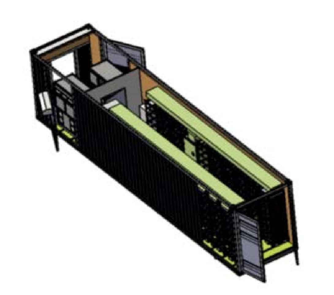
2.1 Air duct structure design
The internal space of the container type battery energy storage system is narrow, and the design requirements for the air duct structure are high. The structure of the heat dissipation air duct of the energy storage system is shown in Figure 2. The air duct includes the main air duct connected to the air conditioning outlet, the wind deflector inside the main air duct, the air duct outlet, and the wind deflector at both ends of the battery rack, arranged symmetrically left and right according to the characteristics of the container. The main air duct is used to convey the airflow output from the air conditioner to the outlets of each air duct; The wind deflector in the main air duct is used to distribute the gas flow rate at the outlet of each air duct, ensuring consistent flow rate at each outlet; The wind deflectors at both ends of the battery rack are used to prevent airflow from escaping from the gap between the battery rack and the inner wall of the container.
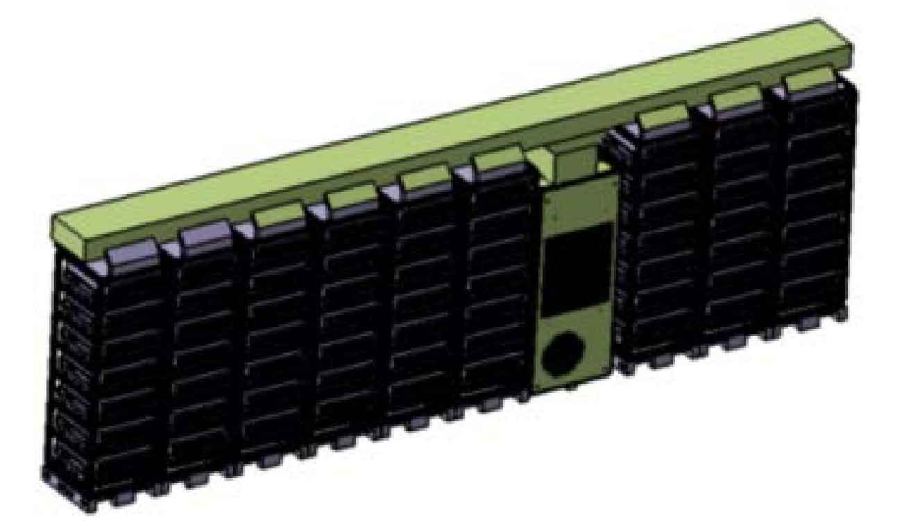
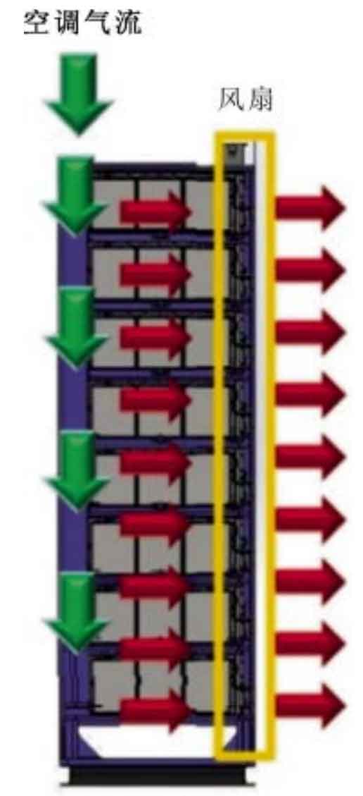
Figure 3 shows the internal gas flow direction of the battery cluster. The air flow output by the air conditioner flows downwards at a certain speed through the air duct outlet. Under the action of the fan on the front panel of the battery module, it enters the interior of the battery module through the air inlet on the rear panel of the battery module, flows through the surface of the battery cell to cool the battery cell, and is then extracted by the fan.
The exterior structure of the battery module is shown in Figure 4 (a), with holes on the rear panel to facilitate the airflow output from the air conditioning to enter the interior of the module; The front panel is designed with an axial fan to extract the airflow and promote its flow inside the battery module. Figure 4 (b) shows the internal gas flow direction of the battery module, with a gap of 3 mm between the battery cells. The airflow enters the interior of the battery module and flows through the surface of the cell, exchanging heat and cold with the cell before being discharged by a fan to complete the cooling of the cell. The thermal control system proposed in this article can ensure that the loss of air flow from the air conditioner is minimal and fully flows through the surface of the battery, resulting in high heat exchange efficiency.
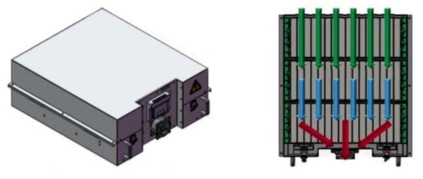
(a) Battery module appearance (b) Internal gas flow direction of battery module
2.2 Design of air conditioning cooling capacity
2.2.1 Calculation of container cooling load
The cooling load inside the container type energy storage system mainly includes the cooling load formed by the heating of batteries, as well as the cooling load formed by the heat transferred into the cabin through the container wall due to the temperature difference inside and outside the cabin and the effect of solar radiation. The energy storage system adopts lithium iron phosphate battery monomers, which are tested for 1 C charge and discharge under laboratory conditions. The energy efficiency of the battery monomers is η。 The cooling load P1 formed by the heating of the energy storage system battery is:
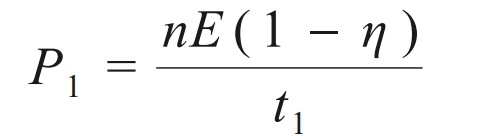
In the formula: n is the number of battery cells in the energy storage system; E is the rated energy of the battery cell, Wh; T1 is the charging and discharging time, h.
The heat transfer and cooling load of containers can be calculated by the heat transfer equation:
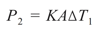
In the formula: K is the heat transfer coefficient, W/(m2 · K); A is the heat exchange area of the container, m2; ∆ T1 is the temperature difference between the inside and outside of the container, K.
From the heat transfer process of the container, it can be seen that convective heat transfer occurs inside, outside, and between the container compartments, while heat transfer occurs between the compartment walls. Therefore, the expression for the heat transfer coefficient K is:
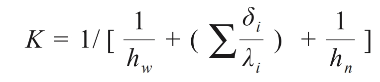
In the formula, hw and hn are the heat transfer coefficients of the outer and inner walls of the cabin, W/(m2 · K); λ I is the thermal conductivity of each layer on the cabin wall, W/(m · K); δ I is the thickness of each layer on the cabin wall, m.
The total cooling load P3 of the energy storage system is:
2.2.2 Design of air conditioning cooling capacity
The heat generated by the battery and the heat transferred from the container wall into the cabin is partially converted into the temperature rise of the equipment inside the container, mainly the temperature rise of the battery. The other part is transported by the air conditioner to the outside of the container through the heat dissipation design of the battery, which is the minimum cooling capacity required by the air conditioner. After the energy storage system is charged and discharged at 1 C, the heat Q1 absorbed by the battery is:
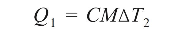
In the formula: C is the specific heat capacity of the battery, J/(kg · K); M is the mass of the battery in the energy storage system, kg; ∆ T2 is the average temperature rise of the battery, K.
The minimum cooling power P4 of the air conditioner can be expressed as:
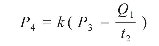
In the formula, k is the safety factor, and the recommended value range is 1.2~1.5; T2 is the charging and discharging time, s.
2.3 Battery module fan design
During the operation of the energy storage system, when the battery temperature reaches a certain value, the fan on the front panel of the battery module starts to assist in cooling. The fan air volume Qf required for heat dissipation of the battery module is:
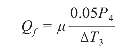
In the equation: μ To consider the incremental coefficient introduced by the internal airflow resistance of the battery module, it is recommended to take values ranging from 1.1 to 1.2; P4 is the heating power of the battery module, W; ∆ T3 is the temperature difference between the inlet and outlet of the battery module, K. The fan model and specifications can be determined based on the heat dissipation airflow requirements of the battery module.
2.4 Insulation design of container compartments
The insulation performance of containers has a significant impact on the temperature inside the container. The worse the insulation performance of containers, the greater the impact of environmental temperature on the temperature inside the container. The insulation design of the energy storage system container mainly considers the insulation and sealing of the cabin, and improves the insulation performance by reducing the heat transfer on the container wall and internal and external air convection. In terms of insulation, the six sides of the container cabin are made of insulated rock wool board with a thickness of 50 mm. The average density of the rock wool board is 120 kg/m3, and the thermal conductivity is ≤ 0.044 W/(m · K). The flame retardant performance is A1 grade, which can effectively improve the insulation and fire resistance performance of the cabin. In terms of sealing, the protection level of the container cabin shall not be lower than IP54.
3.Thermal Management System Control Strategy
The temperature control strategy of the energy storage system includes air conditioning control and battery module fan control. The air conditioning control is achieved by the logical control of the air conditioner itself, which can be divided into heating mode and cooling mode according to different temperature conditions inside the container. The heating mode controls and protects the battery at low temperatures, while the cooling mode effectively controls the temperature rise of the battery. When the internal temperature of the container is below 12 ℃, the air conditioning heating function is activated; When the internal temperature of the container exceeds 28 ℃, the air conditioning cooling function is turned on. The battery module fan is controlled by the battery management system, and each battery module fan can be independently controlled and operated. During the operation of the energy storage system, when the battery management system detects that the temperature of a certain battery module is higher than 33 ℃, the fan of the battery module starts, and stops running when the temperature difference is less than 2 ℃. This temperature control strategy can activate different thermal management control modes based on different working conditions, greatly improving the temperature control ability of the thermal management system. While achieving thermal management performance indicators, it effectively reduces energy consumption of the energy storage system.
4. Experimental verification
Based on the theoretical calculation of thermal management design for containerized energy storage systems, complete the selection and design of air conditioning and battery module fans. When the energy storage system operates under typical operating conditions (1C), the heat generation rate of the system is calculated as 39 kW, and the minimum cooling power required for the air conditioning system is calculated as 24 kW. Therefore, an integrated industrial air conditioner (MC125HDNC1B, produced in Shenzhen) is selected for air conditioning, with a cooling capacity of 12.5 kW, a heating power of 6 kW, and an air volume of 2900 m3/h. The battery module fan shall be an axial flow fan (Y-Y12038H24B, produced in Suzhou) with a rated power of 9.6 W and an air volume of 209 m ^ 3/h.
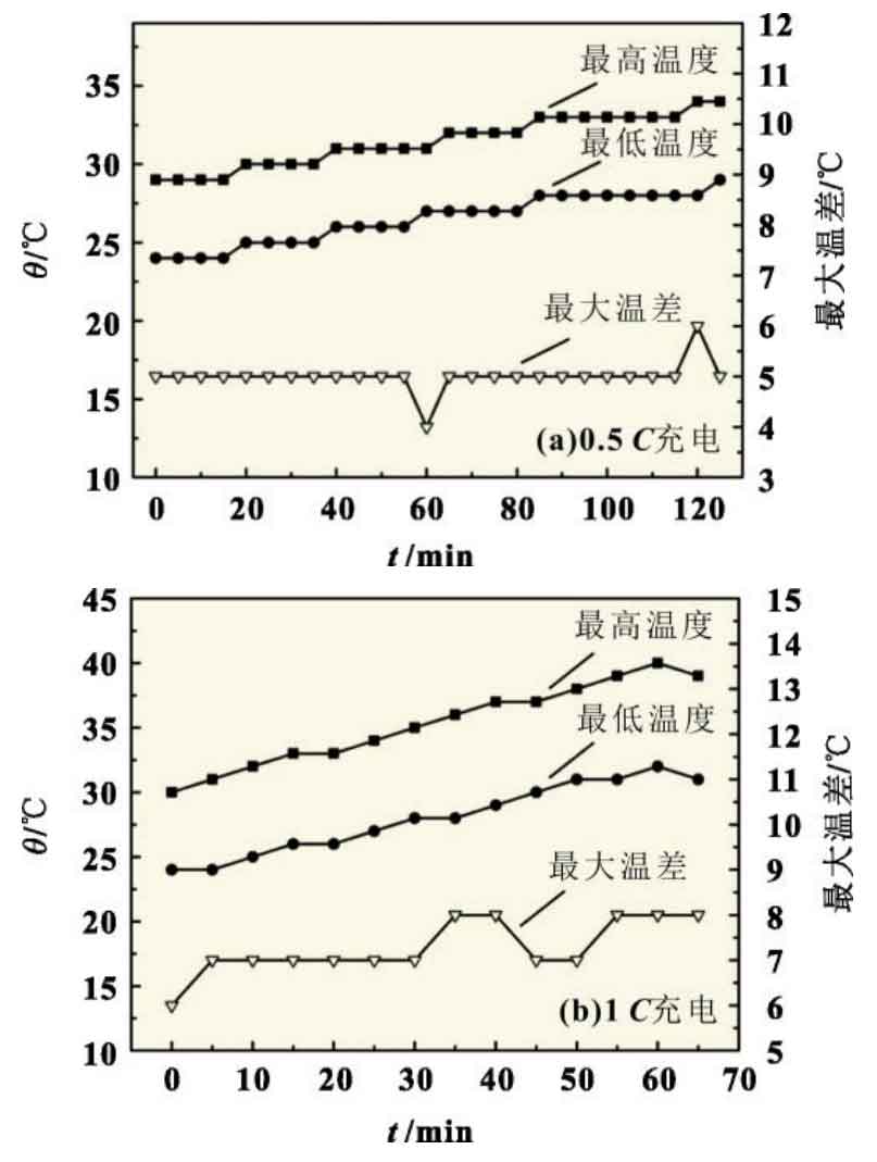
After the integration of the container type energy storage system, charging tests were conducted at an ambient temperature of 35 ℃ at 0.5 C and 1 C, respectively. A battery management system was used to collect and record the temperature changes of the batteries within each battery module. Figure 5 (a) shows that the minimum temperature of the battery has increased from 24 ℃ to 29 ℃, and the maximum temperature has increased from 29 ℃ to 34 ℃. The maximum temperature difference of the energy storage system is basically maintained at 5 ℃. Figure 5 (b) shows that the minimum temperature of the battery has increased from 24 ℃ to 32 ℃, and the maximum temperature of the battery has increased from 30 ℃ to 40 ℃, with a maximum temperature difference of 8 ℃. The results show that the thermal management design can ensure that the energy storage system maintains the ambient temperature in the cabin within the optimal operating range of lithium-ion batteries under low magnification conditions, and the temperature distribution is relatively uniform; Operating at 1 ℃, the operating environment temperature of the battery is maintained below 40 ℃, and the temperature difference is controlled within 8 ℃, thereby improving the operational stability and service life of the container type energy storage system. In addition, the structure of the thermal management system can ensure that the air outlet of the air conditioning basically flows into the interior of the battery module in a closed space, with minimal air loss, and can fully flow through the surface of the battery for heat exchange, resulting in high heat exchange efficiency.
5. Conclusion
Thermal management is of great significance for the safe and reliable operation of containerized battery energy storage systems. However, there is currently no unified understanding of the heat dissipation research of energy storage systems in the industry. How to ensure that a large number of batteries in containers work within a suitable temperature range and have uniform temperature distribution is the biggest challenge in thermal management design. This article focuses on the design of the thermal management system’s cooling duct structure, air conditioning, battery module cooling fan, and temperature control strategy for the megawatt level container type lithium-ion battery energy storage system. At the same time, a container type energy storage system with a rated capacity of 1.2 MWh is designed and integrated. The battery surface temperature distribution of the energy storage system under different operating conditions is tested and analyzed, verifying the rationality and effectiveness of the thermal management system design. The research results indicate that using the designed thermal management system and temperature control strategy can ensure that the maximum temperature of the battery does not exceed 34 ℃ when the energy storage system is charged at 0.5 ℃, and the maximum temperature difference of the energy storage system is basically maintained at 5 ℃. This indicates that when the energy storage system operates at low rates, it can ensure that the battery operates within the optimal temperature range. When charging and operating the energy storage system at 1C, the maximum temperature of the battery should not exceed 40 ℃, and the maximum temperature difference of the energy storage system should be within 8 ℃. The thermal management effect is good.