
In recent years, global sustainable development has faced significant challenges. Moreover, these energy sources seriously pollute the environment during their use, directly affecting people’s health. Therefore, more and more people are turning their attention to renewable solar energy. With the widespread use of solar energy and the maturity of high-power and high brightness lighting LED technology, solar LED street lights have been widely promoted and applied. Solar LED street lights cleverly make low-power lighting sources brighter and more energy-efficient. The LED packaging shell does not require the use of fragile items such as glass as the shell, and it has more impact resistance and pressure resistance. Moreover, solar street lights do not require wiring and can be used without connecting to the power grid. Because solar panels can store electricity under sunlight, they can work in areas with sunlight and have a wide range of applications. Therefore, more and more people are paying attention to the research and application of solar street lights.
1. Design of solar street light controller
Principle of solar street light control: During the day, the solar module converts solar energy into direct current, which is stored in the battery through a solar controller; At night, the battery supplies power to the LED light source through a solar controller, achieving lighting functions. The solar street lamp lighting control circuit consists of four parts: photovoltaic cells, charging and discharging and protection circuits, street lamp controllers, and sensor circuits. In this system, the STC8 microcontroller is used as the core component of the street light controller, providing electricity to the LED lights through solar energy and lithium battery charging and discharging, as well as protection circuits. The ambient light sensor is used to detect the ambient light signal to the controller in order to control the lighting that does not emit light during the day but has conditions at night; Using human body pyroelectric sensors and human body induction radar sensors to determine whether a person is approaching, the signal is sent to the controller to control whether the light is on or off at night, thereby achieving night lighting; Reuse real-time clock signals to the controller to control whether it is necessary to completely turn off or slightly illuminate after the specified time point. The peripheral circuits mainly include solar charging and discharging circuits, charging and discharging protection circuits, human body pyroelectric infrared sensors and detection circuits, human body induction radar signal sensors, etc., which are composed of detection circuits and real-time clock circuits.
2. Hardware circuit design
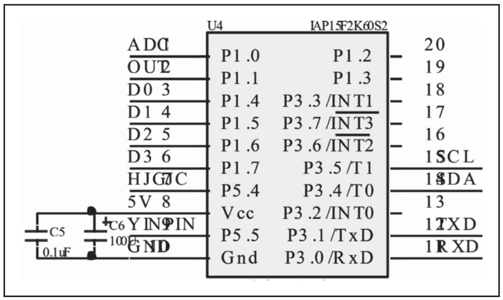
2.1 Intelligent control module of microcontroller
This project uses the latest STC8 microcontroller developed by Nantong Guoxin Microelectronics Technology Co., Ltd. as the core controller. It is a new generation 8051 microcontroller with high speed, high reliability, low power consumption, and strong anti-interference capabilities. The operating voltage range is 3.3V-5.5V, including 2M bytes of on-chip RAM data memory, 1 clock/machine cycle, and an enhanced 8051 core (STC Y5).
2.2 Power circuit module design
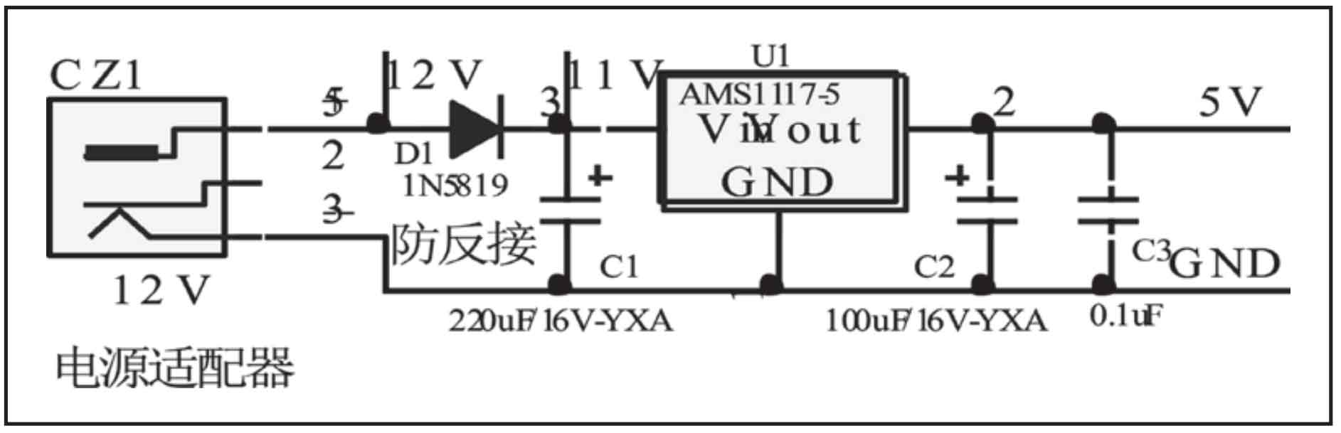
The normal working voltage of the system is 5V, and the system is powered by a 12V/24V lead-acid battery. The controller power is supplied through the positive pole of the battery and introduced through the 1N5819 Schottky diode D1. Among them, 11V in Figure 1 is used as the driving voltage for the transistor. The 11V voltage is stabilized by the AMS117 three terminal adjustable voltage regulator to output 5V voltage, which is provided to the normal working voltage of the microcontroller. The circuit is simple, very convenient to use, stable and reliable in operation. The system power circuit is shown in Figure 2.
2.3 Environmental light detection circuit
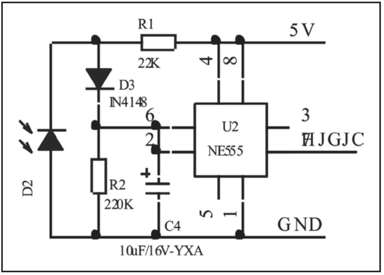
The environmental light detection circuit uses an environmental photodiode (wavelength 450nm) as the component for detecting light. The characteristic of a photodiode is that its resistance will rapidly decrease under specific wavelength light irradiation. The circuit consists of 555 timers, photodiodes, 4148 diodes, resistors, capacitors, and other components. The Schmitt trigger is composed of NE555 and peripheral components, with the main function of anti flicker detection and anti-interference, which is transmitted to the microcontroller. The circuit is shown in Figure 3. The 555 chip and peripheral circuits form a Schmitt trigger, and the photoresistor D2 exhibits a very low resistance value during daylight exposure. Therefore, the threshold terminal ⑥ and trigger terminal ② of the 555 chip are on average higher than 2/3 of the power supply voltage, the integrated block is in a reset state, and pin ③ outputs a low level; When the ambient light becomes dim at night, the photoresistor exhibits high resistance, causing a decrease in the level of pin ② at the trigger end of the integrated block. When it drops to 1/3 of the power supply voltage, pin ③ of the 555 circuit outputs a high level. R2 and C4 form an integral circuit, which plays a role in absorbing and anti-interference, preventing the circuit from flipping incorrectly at night.
2.4 Human body sensing module circuit
This project uses two sensor modules, including a pyroelectric sensor module and a human radar sensor module. It is a sensor that can detect infrared radiation emitted by humans or animals and output electrical signals. The BISS0001 chip is used here, and its biggest advantage is stable and reliable performance. The working voltage is DC6-24V, and the sensing distance is 0.5-5 meters. When the human body enters the sensing detection range, it outputs a 3V high level, and when there is no one, it outputs a 0V low level. Due to the close detection distance of the pyroelectric sensor, an additional radar sensor is added to expand the detection range. The radar sensor has a long sensing distance and strong reliability. With a wide working voltage range, it is a microwave induction module specifically designed to detect the movement of objects, combined with a human body pyroelectric sensor to detect the presence of people approaching the solar street light controller. The maximum detection range can reach 9 meters, thereby controlling the on and off of street lights and achieving street light control lighting. The circuit interface of the human body sensing module is shown in Figure 4.

2.5 Drive Circuit
The LED lights of the terminal equipment in this project require certain conditions for illumination, and the working current must meet an appropriate numerical range. The working current cannot be too large or too small. If the current is too small, it will burn out the LED lights. If it is too small, the luminous efficiency will be reduced, and the purpose of illumination cannot be achieved. It is necessary to limit the working current of the LED, while considering the driving voltage of the LED. Therefore, SIS302 field-effect transistor is used to drive whether the LED lights emit light.

2.6 Selection of solar panels for solar street lights
Solar cells are devices that use the photovoltaic effect to directly convert solar energy into electrical energy. Solar panels mainly include monocrystalline silicon and polycrystalline silicon. The photoelectric conversion efficiency of monocrystalline silicon solar energy is as high as 24%, which is the highest among all solar cells. It has a long service life, but high production costs. Although the price of monocrystalline silicon is high, monocrystalline silicon solar panels are still used in this project. The rated voltage of a single solar panel is 5V, the rated current is 200mA, and the rated power is 1000W. Two solar panels are connected in series to increase their operating power and to charge them more quickly.
2.7 Audio signal processing circuit
When someone approaches solar street lights at night, the controller collects sound signals. Used here. Due to the advantages of simple structure, small size, high cost-effectiveness, and good acoustic and electrical performance, we have chosen an electret microphone as the sensor for acoustic signal acquisition.
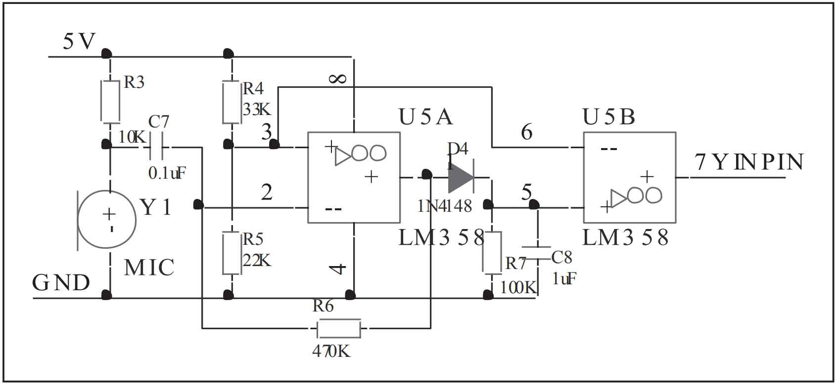
When there is no sound, only a low voltage signal is output. When there is sound, it will output a voltage value amplified by the integrated operational amplifier. The audio signal processing circuit converts speech signals into weak mv electrical signals through an electret microphone. The electrical signal is amplified into a voltage signal of volts through a two-stage amplification circuit composed of an integrated operational amplifier 358. The voltage signal is sent to the microcontroller controller for comparison with the reference voltage to obtain the voltage threshold for triggering illumination. When the signal voltage exceeds the threshold, determine that the ambient volume reaches the preset level to trigger illumination. The audio signal processing circuit is shown in Figure 6.
3. Software Design
When the power switch is pressed, the system first initializes the program. In the initialization program, the timer and interrupt of the microcontroller are mainly initialized, and then the solar cell photosensitive plate is used to detect whether it is at night. If the detection result is not at night, start charging the battery under the monitoring of the controller; If the result is at night, make the LED light illuminate.
4. Conclusion
The controller is an important component of the solar street light system. Its performance directly affects the reliability of the system. This article uses STC microcontroller and other chips as well as peripheral circuits to design a solar street light controller. After hardware testing and software programming control, the system runs well and can meet the lighting needs of the community, meeting the design requirements! It is a product that can be promoted.