
At present, many cities in China are using low energy consumption and high-power street lighting systems, which leads to significant energy waste; Moreover, traditional street light systems have a single function, low monitoring efficiency, and cannot meet the current theme of low-carbon, environmentally friendly, and safe travel.
The third-order Kalman collaborative filtering used in this article is not only applicable to stationary random processes, but also to non-stationary random processes. It uses a fixed dimensional matrix to replace a system of linear equations with huge dimensions, greatly reducing computational difficulty and improving computational speed. In terms of noise processing, third-order Kalman collaborative filtering can establish an accurate system model because it takes into account system noise and measurement noise, which can effectively suppress noise interference and improve data accuracy. This system is a street light control system that uses solar power and can detect the brightness of the external environment. By using third-order Kalman collaborative filtering to obtain smooth data, the external environment detection circuit provides signals to the controller to turn on the street lights. The system has functions such as external detection and intelligent solar power supply.
1.Overall system design scheme
The designed solar street light system based on collaborative filtering control algorithm includes a solar panel, OPT3006YMFR sensor, human infrared sensing module, LED light, DS1302 clock module, LCD1602 display module, input keyboard, encoder, and MCU control chip. The OPT3006YMFR sensor module is used to detect the brightness intensity of the external environment. The collected brightness intensity is transmitted to the MCU controller through the IO bus as input, and the MCU controller adjusts the brightness level of the light based on the input; Module CN101861021A serves as the driving device for LED lights, adjusting the brightness of the LED lights by receiving DPWM signals; The DS1302 clock module is used to calculate and save time, and can also achieve real-time updates of time; The LCD1602 display module is used to display the current time and system status, and can achieve intelligent interaction.
2. Hardware circuit design
2.1 External Environment Brightness Detection Unit
The external detection unit uses OPT3006YMFR sensor and uses IO bus as the digital transmission interface. The sensor has a 32-bit ADC converter inside, which converts the optical signal of the photodiode into a corresponding digital signal and transmits it. The highest sensitivity of the sensor is 570 nm, and it can operate between -40 ℃ and+85 ℃ with stable performance. Its interface with MCU is shown in Figure 1.
2.2 LED driver circuit
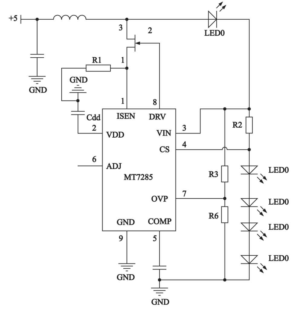
This article selects MT7285 as the LED driver circuit. MT7285 supports PWM dimming and analog dimming through a single control pin, which can achieve mild and stable LED lights. The MT7285 adopts high current detection technology, which can set the average operating current of the LED through external resistors. The low reference voltage of 205 mV effectively reduces power loss and improves efficiency. MT7285 supports both analog dimming and PWM dimming. When simulating dimming, when the ADJ pin voltage is adjusted from 0.8 V to 1.6 V, the LED current will change from 0 to 100%. If the voltage of the ADJ pin is higher than 1.6 V, the LED current will remain at 100%. When PWM dimming, the ADJ pin must receive a high-level voltage exceeding 1.6 V. Apply a PWM signal of 100 Hz to 10 kHz to the ADJ pin, and as the duty cycle changes, the LED current changes from 5% to 100%. When the voltage of the ADJ pin is below 0.2 V, the chip is turned off. The driving circuit diagram is shown in Figure 2.
2.3 Communication module
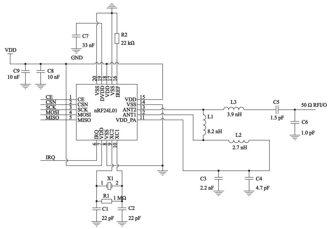
This article uses the NRF24L01 module for communication transmission. NRF24L01 adopts DIP-8 size packaging, produced by NORDIC company, and can perform single chip wireless transmission and reception in the frequency range of 2.40 GHz to 2.52 GHz. This module has the characteristics of simple debugging, long communication distance, low cost, and high transmission rate, which can more efficiently transmit the data collected by each node to the MCU. It can operate within the range of 1.9 V to 3.6 V, and the input pin can withstand a voltage of 5 V; Equipped with 4-wire SPI communication ports, the maximum communication speed can reach 8 Mbit/s. Figure 3 shows the circuit schematic of NRF24L01.
2.4 MCU control unit
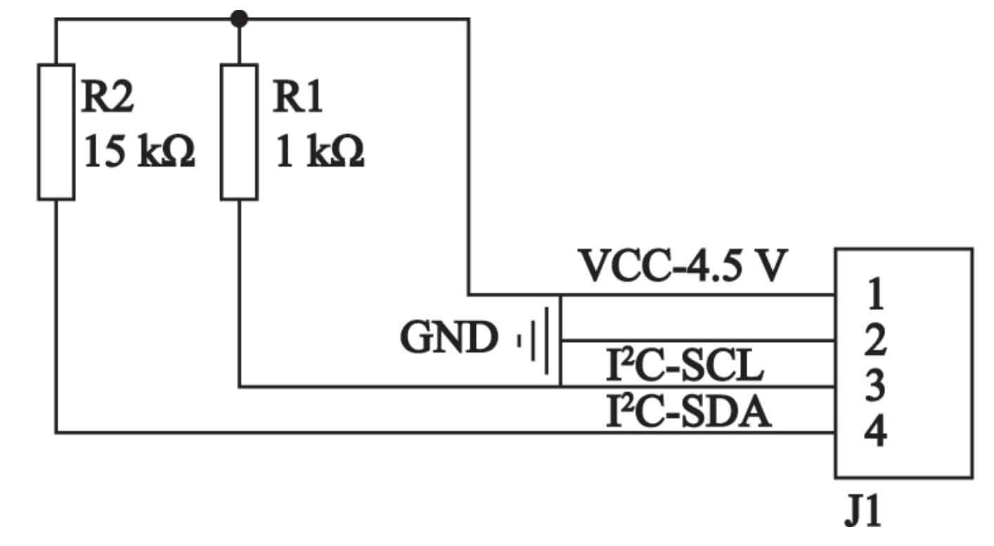
The MCU control unit selected in this article is the STM32F103VET6 microcontroller, which has 100 pins and uses a 32-bit Cortex core with rich interfaces. The operating frequency can reach up to 72 MHz. Here, the control unit STM32F103VET6 microcontroller is connected to the communication module NRF24L01. Among them, PA2 is connected to CE, PA3 is connected to CSN, PA5 is connected to SCK, PA6 is connected to MOSI, PA7 is connected to MISO, PA8 is connected to IRQ, and PA9 is connected to ANT2. The control unit STM32F103VET6 microcontroller is connected to the external environment detection sensor OPT3006YMFR. Among them, PB10 is connected to I2C-SCL, and PB11 is connected to I2C-SDA. The control unit STM32F103VET6 microcontroller is connected to the LED driver circuit, where PD0 outputs a PWM signal and is connected to the ADJ pin in MT7285.
3. Software system design
3.1 Main System Design Procedures
After powering on, initialize the data in each register and the internal chip of the external environment detection sensor to prepare for data cyclic reception and transmission. By cyclically collecting data from external environment detection sensors and clock modules for wireless data communication, the controller MCU can be informed of its status information and control data. Afterwards, check if it is the specified time for the street lights to be turned on, and if so, turn on the street lights; If not, use external environmental sensors to detect external brightness data and analyze it through collaborative filtering algorithms to determine the degree of external brightness.
If it is daytime, calculate the angle difference between the solar panel and the sun based on collaborative filtering, and finally use a motor to adjust the angle, making the charging efficiency of the solar panel more efficient.
3.2 Maximum power tracking strategy for solar panels
This article adopts the intermittent tracking method to establish a motion tracking equation. After collecting data, the optocoupler calculates the solar angle using a three-dimensional Kalman collaborative filtering algorithm, and then uses the desired pulse signal to drive the motor and adjust the angle of the solar panel. The motion tracking equation is as follows:
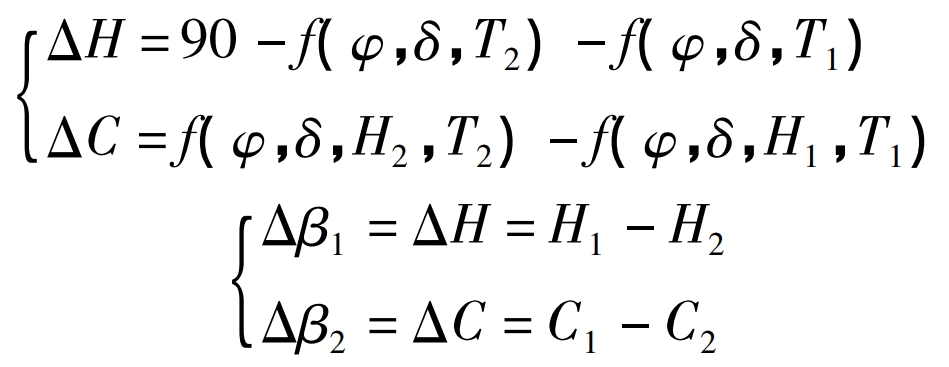
In the formula: T1 represents the current position time, the current height and rotation angle of the solar panel are H1 and C1, H2 and C2 represent the height and angle of the solar panel at time H2, respectively. According to the intermittent tracking method, the variation in height error of the solar panel is Δ H. The corresponding motor rotation angle is Δβ 1. The change in azimuth error is Δ C. The corresponding motor rotation angle is Δβ 2. When Δβ If the value of 1 is greater than zero, the motor will rotate forward Δβ If the value is less than zero, the motor will reverse.
3.3 Communication Protocol
The NRF24L01 module used here is a universal engineering medical frequency band wireless transceiver chip that can transmit data through the SPI bus. The input speed can reach up to 2 Mbit/s, and the output data speed is faster, up to 10 Mbit/s. This system uses it to implement a fast and lightweight communication protocol. The data of NRF24L01 consists of five main parts, namely pre code, payload, address code, packet control segment, and cyclic redundancy check.
4. System debugging and analysis
4.1 Brightness collection test
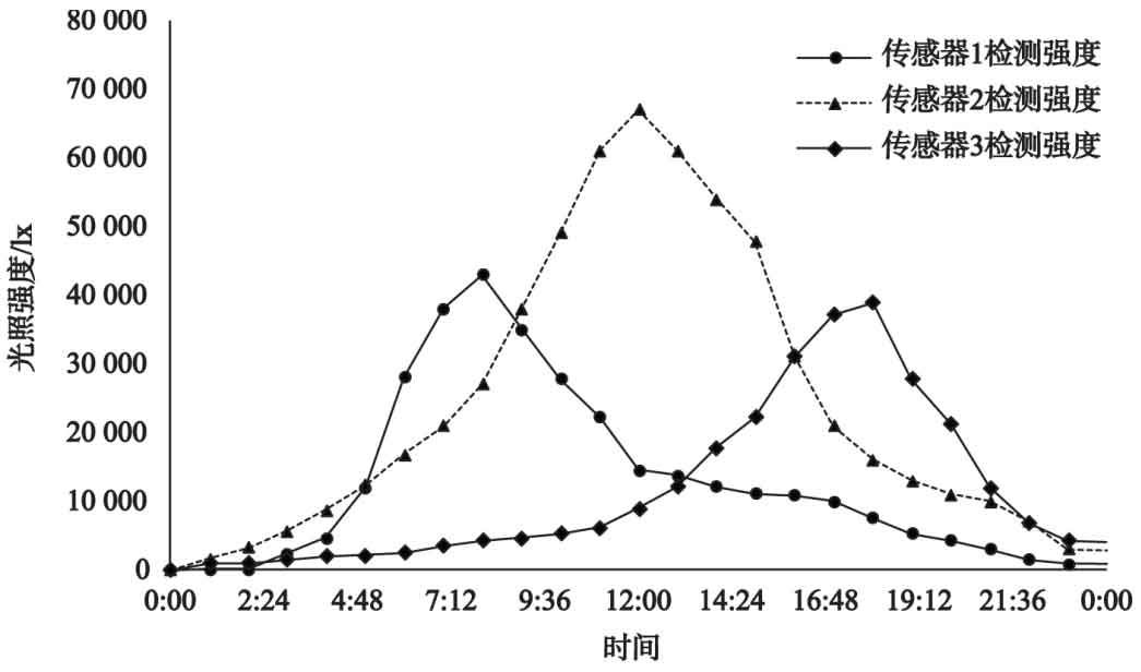
Here, three-dimensional Kalman collaborative filtering is used for data filtering and processing. After processing, it is sent to the MCU controller for calculation. After calculation, the return value is sent to the LED driver circuit to drive the lighting of the LED light. In order to verify the data acquisition algorithm designed for this system, three OPT3006YMFR brightness detection sensors were placed at the top of the street lights to perform collaborative algorithm processing on the measured data, removing various interferences and white noise, so that the final displayed external brightness intensity data reaches the true value. Figure 4 shows three types of data information detected by three sensors, with time displayed on the horizontal axis and daily light intensity displayed on the vertical axis.
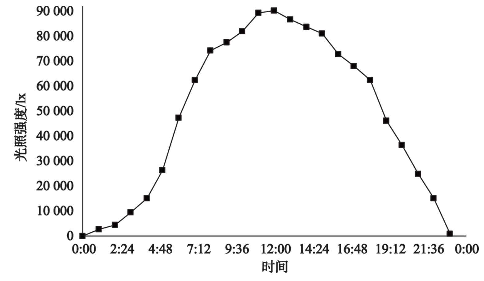
By using the algorithm of three-dimensional Kalman collaborative filtering, various disturbances were removed and finally approximated to obtain a complete all-weather external light intensity map, as shown in Figure 5.
4.2 Control testing of ray tracing solar panels
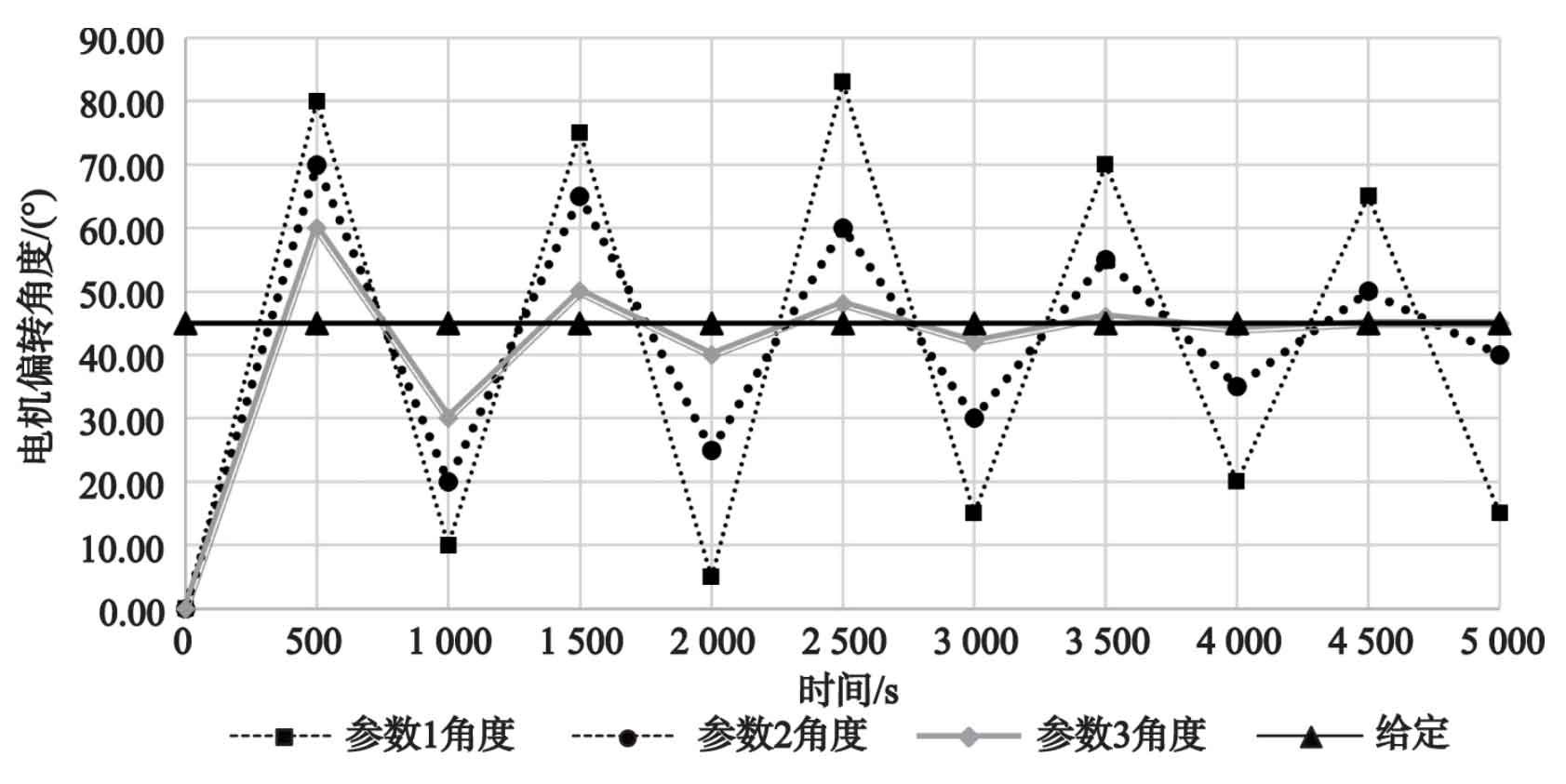
The solar panel tracking system in this article adopts PD control, and the overshoot and response time of the system vary under different PD parameters. The incremental PD control is adopted here, and the formula is as follows:
V (t)=Kd · [c (t+1) – c (t)]+Kd · e (t+1)
In the formula: v (t) is the output value, and c (t) is the deviation value. In order to adjust the angle of the solar panel, achieve light tracing control, and improve solar energy utilization efficiency, the method of first adjusting Kp and then adjusting Kd is adopted. Figure 6 shows the step response when adjusting the solar panel to a 45 ° angle. Among them, P=4 and D=1 in parameter 1; Parameter 2: P=2, D=3; In parameter 3, P=1.536 4 and D=1. This article chooses parameter 3 because it has no overshoot and a period of 1, which can achieve speed and stability.
5. Conclusion
The design is a solar street light control system based on collaborative filtering algorithm, using STM32F103VET6 microcontroller as the main controller of this system, combined with OPT3006YMFR sensor and 3D Kalman collaborative filtering algorithm to obtain relatively complete and stable external environment data collection. Then, the solar panel is combined with a PD controller to achieve light tracing control of the solar panel, greatly improving the efficiency of solar energy utilization. The experimental results indicate that the parameters adjusted in this article can well meet the performance requirements of the system and have practical application value.