
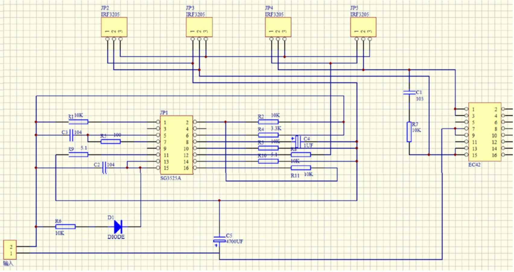
The design is centered around SG3525A, where a 50Hz sine wave signal is first generated by an oscillation circuit. The rectifier circuit rectifies and amplifies the waveform, and then sends the signal to the compensation signal terminal of SG3525A to form negative feedback, ultimately outputting a relatively standard sine wave. The EC42/EE42 high-frequency transformer is used to boost the output signal and output 220V AC mains power for general household appliances. AC power with a rated output power of around 50W (input DC voltage of 12V, output AC voltage of 160V~220V~380V). This design utilizes a solar photovoltaic inverter based on solar energy to convert solar energy to 220V AC power. It not only has low production cost and simple structure, but also is suitable for general household appliances.
Solar energy is currently one of the most abundant renewable energy sources on Earth, an inexhaustible and clean new energy source. Solar energy is also a pollution-free and safe new energy source, in line with the concept of sustainable development. The use of solar energy will not cause pollution or damage to the environment like fossil fuels such as natural gas, oil, and nuclear energy. Hainan itself has unique geographical conditions and belongs to a region with abundant solar energy resources in China. It has long sunshine hours and a large total solar radiation throughout the year.
This design first converts solar energy into stable DC direct current to charge the battery. After the battery is charged, the controller automatically stops charging through the solar controller to prevent overcharging and damage to the battery. The solar photovoltaic inverter connected to the battery converts direct current into AC alternating current for output. Compared to ordinary power sources, solar photovoltaic inverters have significant advantages. After being stabilized by a solar controller, the solar photovoltaic power generation panel charges stably and generates no pollutants during the process, which is of great significance for improving the overall environment of the Earth and alleviating the consumption of fossil fuels.
1. System design
1.1 Structural composition of solar photovoltaic inverters
This design consists of six parts, including solar photovoltaic panels, solar controllers, batteries, inverter systems, DC outputs, AC outputs, etc. The basic composition is shown in Figure 1.
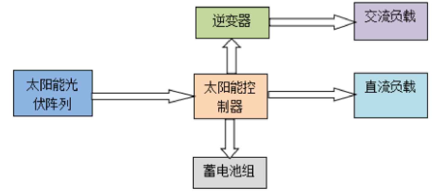
Solar photovoltaic panel: Utilizing a P-N junction structure to convert solar energy into electrical energy and output direct current. Solar controller: Stabilizes the DC voltage output from the front stage, providing stable DC voltage for the rear stage, ensuring the normal use of the battery and inverter system, and can output 5V DC power. Solar photovoltaic inverter: Obtaining DC power from solar photovoltaic panels or batteries, converting DC power into AC power that meets the requirements of household appliances. Battery pack: Its purpose is to store excess electrical energy for emergency use.
1.2 Basic structure of solar photovoltaic power inverter
Firstly, the DC voltage is provided by the battery or solar photovoltaic panel, and an approximate sine wave is generated through the inverter circuit. Then, a standard sine wave is obtained through LC filtering, and the EE42 high-frequency transformer is used to boost the upper output to 220VAC. This design is carried out by a photovoltaic power source for inversion. During use, the battery may experience undervoltage. In terms of circuit design, consideration should be given to the design of undervoltage protection and output overcurrent protection. Real time sampling of input and output waveforms in the circuit to achieve protection against input undervoltage and output overcurrent. The basic structural diagram of the solar photovoltaic power inverter is shown in Figure 2.

1.3 Design requirements for solar photovoltaic power inverters
The performance parameters of this design are shown in Table 1.
| Input | DC voltage | 12V |
| Input | Battery index | 12V/10Ahx4 |
| Input | Maximum charging capacity | 4A |
| Output | Voltage (effective value) | 220V |
| Output | Output rated current | 0.5A |
| Output | Frequency | 50Hz |
1.4 Inverter circuit design
The circuit diagram design of the solar photovoltaic inverter in this design is shown in Figure 3:
2. Physical performance testing
2.1 Solar photovoltaic panel to battery charging test
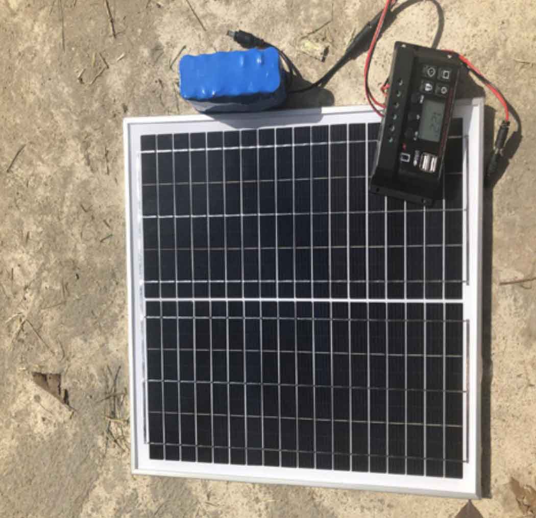
When charging the battery, the maximum current provided by the solar panel should be less than or equal to 0.2c (c is the battery capacity). To prevent the battery from burning out due to the high voltage of the solar panel during charging, the open circuit voltage of the solar panel photovoltaic panel must be less than the maximum voltage allowed to be connected to the battery voltage protection panel. Therefore, this design uses a 20W solar photovoltaic panel to charge and discharge a 12v/10000mA lithium battery through a solar controller. After connecting the battery and solar panel in the order of connection, connect the load and test the output voltage and current of the solar panel.
When charging, the solar controller will automatically recognize the type of battery. Charging adopts a complete 3-stage PWM charging management for charging. At the beginning, the controller detects that the battery level is three segments, and the charging label is constantly on, indicating that direct charging/boost charging is in progress. After the battery is charged to a certain capacity, the charging label of the controller will slowly flash and use float charging voltage or constant voltage (12.6V) charging until it is fully charged. The test is conducted as shown in Figure 4, and the battery test results are shown in Table 2.
| Serial number | Initial voltage (V) | End voltage (V) | Angle to Sun (°) | Charging time (H) |
| 1 | 9.0 | 12.6 | 90 | 3.5 |
| 2 | 8.9 | 12.5 | 90 | 3.6 |
| 3 | 9.0 | 12.6 | 60 | 4.0 |
| 4 | 8.8 | 12.6 | 60 | 4.1 |
| 5 | 8.8 | 12.8 | 90 | 3.6 |
From the above table, it can be seen that in the solar photovoltaic inverter system, the charging part of the battery takes about 4 hours to fully charge, and it is also related to the angle between the solar panel and the sun and the light intensity. If you want to reduce the charging time, you can place it perpendicular to the sunlight and conduct it in a well lit environment. After the charging is completed, the solar charging controller can also automatically power off to prevent overcharging.
2.2 Charging parameters of solar photovoltaic panels and batteries during charging
When testing charging parameters, first place the solar photovoltaic inverter in an open area to make it as direct as possible with the sun. By adjusting the angle between the polycrystalline silicon solar photovoltaic panel and the sunlight, different data can be measured, and the battery voltage can be obtained on the LED display screen of the solar controller. When unloaded, the output voltage of the solar photovoltaic panel can be read, The input current and output voltage are tested using the DC current and AC voltage ranges of a multimeter, and plotted into a table for data analysis. The test results are shown in Table 3.
| Solar panel input voltage (V) | Solar panel input current (A) | Battery output voltage (V) | Battery output current (A) | Inverter output voltage (V) |
| 20.6 | 1.11 | 12.6 | 1.5 | 232 |
| 20.5 | 1.25 | 12.4 | 1.5 | 228 |
| 20.6 | 1.12 | 12.6 | 1.5 | 220 |
| 20.6 | 1.13 | 12.5 | 1.6 | 230 |
| 20.5 | 1.18 | 12.6 | 1.5 | 218 |
| 20.6 | 1.16 | 12.2 | 1.6 | 220 |
From Table 3, it can be seen that under the conditions of open environment and sufficient lighting, the input voltage and current of the solar photovoltaic panel are basically constant, and the output voltage of the battery is also constant. It can be concluded that the output power of the solar photovoltaic inverter in this design is basically constant.
2.3 Charging Test for Ordinary Electrical Appliances
Without connecting any electrical appliances, the circuit can be used normally. After the circuit board switch is pressed, the green indicator light will light up normally and output normal 220V AC power. The indicator light will light up normally when the plug board switch is pressed. Next, taking mobile phones, electric vehicles, and desk lamps as examples, this design is used to conduct charging tests on electric vehicles, mobile phones, desk lamps, and other electrical appliances. The test results are shown in Table 4.
| Charging products | Initial power consumption (%) | End Charge (%) | Charging time (H) | Initial battery capacity (%) | Battery End Charge (%) | Effect |
| Android phone | 0 | 100 | 2.8 | 100 | 50 | Normal |
| IPhone phone | 10 | 100 | 2.6 | 75 | 25 | Normal |
| 48V electric vehicle | 0 | 80 | 5 | 100 | 0 | Chip heating |
| 36V electric vehicle | 0 | 100 | 5 | 100 | 0 | Chip heating |
| Desk lamp | — | — | — | 100 | 75 | Normal |
After testing and analyzing the charging results of some ordinary electrical appliances, the solar photovoltaic inverter operates normally and can basically achieve the expected effect of this design. The charging process for completing an electric vehicle takes approximately 6 to 8 hours. After the electric vehicle is fully charged, the battery in the device is also depleted. If you want to improve usage time, you can replace the battery with a larger capacity under sufficient lighting conditions. It takes approximately 2.5 to 3 hours for a mobile phone. If you want to shorten the charging time, you can choose to increase the input current of the solar panel and increase its output power. Alternatively, try to place the solar panels perpendicular to the sunlight. At the same time, solar panels, batteries, and solar photovoltaic inverter modules can be flexibly disassembled, and the battery part can be charged separately using the solar panel, or only the battery and solar photovoltaic inverter part can be used for inverter output. The design is flexible and diverse, making it easy to replace a single part after damage, improving the convenience of use and greatly reducing costs.
3. Conclusion
The design system of solar photovoltaic inverter has stable performance and simple circuit structure, which reduces the cost of its solar photovoltaic inverter circuit and has good output waveform. The design is modularized to facilitate users’ use. The charging and discharging parts can be separated or used at the same time. In terms of later maintenance, it is also greatly convenient for users. A single module can be replaced or repaired after a module is abnormal, Multiple batteries can be used together, and when using one battery for inverter, other batteries can also be charged. This design has a wide range of applications and can be installed in electric vehicle sheds. During the day, solar energy is used to invert the charging of electric vehicles, and at night, the energy inside the battery is used to invert the charging to provide electric energy for electric vehicles. It can also be widely used in common household appliances. After the product circuit integration and appearance design packaging are improved, this design can provide more convenient services for people, providing 220V and other AC power anytime and anywhere.