
Nowadays, there are more and more mobile electronic devices on the market, but the power capacity and power consumption of the devices cannot meet the market requirements, causing inconvenience to daily life, especially outdoor activities. Therefore, this article designs an efficient, low-power, and safe portable power supply to meet outdoor needs, which will have great practical value. The system design consists of five parts: lithium cell capacity indicator circuit, battery protection circuit, charging management circuit, and DC-DC boost circuit. The lithium cell capacity indicator circuit is composed of voltage monitoring chips from the XC61CC series. The battery cell protection circuit consists of three parts: overcharge protection, over discharge protection, and over temperature protection. The HAT2027, R5402, and self recovery fuse construct a triple protection, greatly enhancing the safety of the lithium cell. The charging management circuit adopts CN3066, which divides the charging process into four parts: trickle charging, constant current charging, constant voltage charging, and maintenance charging, enabling the mobile portable power supply to store energy to the maximum extent possible. The DC-DC boost circuit adopts the MAX1771 integrated chip, which can maximize the release of lithium cell capacity within a safe range, achieving the purpose of supplying power to various digital devices.
1. Working principle of circuit
1.1 Lithium ion protection circuit
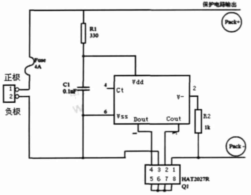
As shown in Figure 1, the battery cell protection circuit is mainly composed of R5402 and HAT2027 together. In addition, the self-healing fuse serves as the final layer of protection. When charging, the battery voltage increases from low to high. When the battery voltage is greater than 4.25V, the charging state is locked, and the pin Cout will jump from high to low. The built-in diode of HAT2027 plays a one-way conduction role. The current direction can only go from pin 1 to pin 3, and the charging power supply cannot continue to charge the lithium cell. If the charging power continues to be loaded at both ends of the lithium-ion battery pack, even if the lithium-ion voltage is below 4.25V, the overcharge latch state of R5402 will not be released. This ensures that the battery pack can be locked in an overcharge state after continuous charging saturation, isolating the charging power source to continuously charge the high-energy battery pack. Only when the charging power is disconnected during overcharging will the overcharge latch state be released, Cout will return to high level, and pins 1 and 3 of HAT2027 will conduct in both directions, allowing the lithium cell to function normally. When discharging, the battery voltage drops. When it is less than 2.3V, the discharge state is locked, and the output of pin Dout jumps from high level to low level. The built-in diode of HAT2027 plays a unidirectional conduction role. The current direction can only go from pin 3 to pin 1, and the lithium-ion battery pack cannot continue to discharge the load. If the charging power supply is not connected, even if the lithium cell voltage is higher than the maximum value of the over discharge voltage, the discharge latch state will not be released. This ensures that the battery pack can be locked in the over discharge state after a long period of discharge and the voltage drops to 2.3V, isolating the low-energy battery pack for continuous discharge. Only when the over discharge occurs and the charging power supply is connected, and the voltage of the lithium cell begins to exceed the over discharge voltage, will the over discharge latch state be released. At the same time, the voltage of pin Dout will return to high level, and pins 1 and 3 of HAT2027 will conduct in both directions. The lithium cell can work in both discharge and charging states. When the lithium cell is short circuited, Dout jumps to a low level. At this time, the lithium cell is controlled by HAT2027 and cannot discharge, which serves to protect the lithium cell. At the same time, the self-healing fuse will expand due to the high current of the short circuit, causing the circuit to cut off and serving as the final layer of protection. When the short circuit fault is resolved, the white recovery fuse is restored, the R5402 detector is released, and the Dout returns to high level.
1.2 DC-DC Boost Circuit
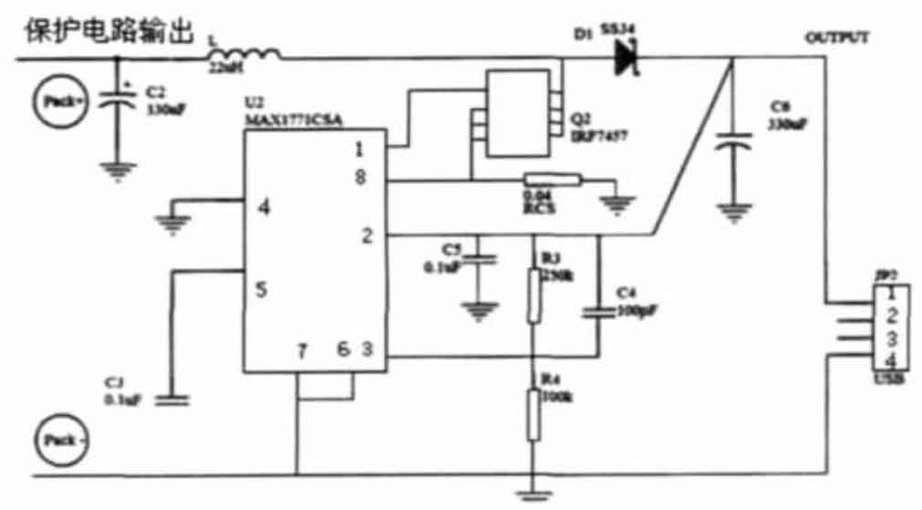
In this system, the DC-DC boost circuit is mainly composed of MAX1771, which adopts a unique control scheme and combines the advantages of PFM (Pulse Frequency Modulation) and PWM (Pulse Width Modulation) to provide an efficient and wide voltage regulation range power supply. The former has a smaller static current, higher efficiency under small loads, but larger ripple. The latter has high efficiency and low noise under heavy loads. The controller adopts an improved current limiting PFM control method, which controls the circuit to limit the charging current of the inductor to not exceed a certain peak current. It not only maintains the low static current of traditional PFM, but also has high efficiency under larger loads. Moreover, due to the limitation of peak current, using small peripheral components can achieve satisfactory output ripple, which is conducive to reducing circuit costs and size. As shown in Figure 2, grounding the four pins can make it work in a closed loop state. The chip is powered by the voltage on pin 2, which is also the output voltage. The input voltage can vary from 2V to the output voltage. The voltage on pin 1 of the external MOS transistor gate jumps from the output level to the zero level, providing more efficient gate driving and reducing the opening resistance of the external MOS transistor. The MAX1771 external MOSFET is usually turned off, and at this time, the inductor stores energy. During the shutdown period, MAX1771 will detect the external input voltage. Once it drops to a certain limit, MAX1771 will activate the external MOSFET, release energy from the inductor, and provide the driving voltage again. The switching frequency is determined by the load current and input voltage. The 5V voltage is obtained by dividing the voltage through two feedback resistors. In addition, the freewheeling diode uses the Schottky diode SS34, which has a small forward conduction voltage and short response time.
1.3 Lithium cell capacity indicator circuit
The circuit design of this system adopts a relatively simple and practical method, which is to test the time voltage characteristic curve of lithium-ion battery discharge, select four voltage points throughout the discharge process, and estimate the battery capacity using the voltage. When the voltage capacity indicator function button is pressed, the battery voltage of the lithium cell will be applied to the VIN and VSS pins of the XC61 series chip. When the voltage is as high as 4.1V, all four chips work simultaneously, and the battery forms four circuits with current limiting resistors and LED light-emitting tubes. At this time, all four light-emitting tubes light up simultaneously, indicating that the battery capacity is saturated. When the battery voltage is between 4.1V and 3.8V, only three chips are working and 4102 is not working, three circuits are formed, and the three light-emitting tubes light up, indicating a decrease in battery capacity. Similarly, it can be inferred that there are two other situations.
1.4 Charging management circuit
The charging management circuit consists of CN3066 and a relay. When the portable power supply detects a charger charging it, the relay causes CN3066 to start working. CN3066 divides the entire charging management process into four parts: pre charging, constant current charging, constant voltage charging, and maintenance charging. When CN3066 starts working, it will detect whether the battery voltage is low. If so, trickle charging is used, which means a relatively small constant current is used to charge the battery until the battery voltage rises to a safe value. Afterwards, the charging current remains relatively high, usually 10 times or more than the trickle charging current. A 1000mAh battery is charged with 700mA current, which can avoid damage to the lithium cell caused by high current charging. In constant current and trickle charging states, the charging management chip continuously monitors the voltage of the battery. When the voltage of a single lithium battery reaches 4.2V, the constant current charging state ends and enters the constant voltage charging state. In this state, the charging voltage remains constant at 4.2V. When the current of the lithium cell drops to 1/10 of its original value, the constant voltage charging state ends. If the mobile power supply is still plugged into the charger after maintaining the charging state and the battery is fully charged, the battery will lose power due to self discharge. CN3066 charges the lithium cell with a very small current or monitors the battery potential in preparation for recharging the lithium cell, which is called maintenance charging state.
In this circuit, CN3066 will monitor the voltage, temperature, charging current, and charging time of the lithium cell in real time. Once the temperature of the battery reaches 60 ℃ or the voltage of the lithium-ion battery reaches 4.2V, the constant voltage charging state automatically terminates. In addition, the longest constant voltage charging time should also be set. In the event of temperature and voltage detection failure, it can ensure safe charging of lithium batteries. When the charger is unplugged, CN3066 is turned off and the portable power supply is in a pre discharge state.
The experimental results have shown that the multifunctional portable power supply can continuously charge most mobile phones on the market for more than 5 times, and charge MP3 and MP4 for more than 12 times, indicating that the portable power supply has sufficient energy reserves for outdoor activities.
2. Conclusion
The design of this system scheme integrates many features such as multifunctionality, low power consumption, safety, high capacity, and light weight, making the entire product design meet practical usage requirements and have broad market prospects. This plan scientifically and meticulously eliminates various safety hazards that may arise during the use of lithium cells.