
At present, mobile power sources are mainly divided into three types: mobile batteries, mobile power banks, and new energy independent power sources, namely solar powered mobile power sources.
Mobile batteries are divided into regular batteries and maintenance free batteries. The plates of regular batteries are composed of lead oxides, and the electrolyte is an aqueous solution of sulfuric acid. The main advantages are stable voltage and low cost; The disadvantages are low specific energy, short service life, frequent daily maintenance, and a significant decrease in battery storage capacity after multiple charging and discharging. The advantage of maintenance free batteries is that the consumption of electrolyte is very small, and there is basically no need to replenish electrolyte during its service life. It is also resistant to shock, high temperature, small volume, and small self discharge; The disadvantage is that the liquid addition process is cumbersome to operate, with low recyclability, and frequent use can cause extremely poor battery life.
Mobile power banks are generally used to charge digital devices such as smartphones, tablets, cameras, etc. Its advantage is that it is extremely convenient to carry, but it has a small capacity and fast discharge. Due to the almost constant discharge voltage, it is difficult to predict when the discharge will end, and the battery voltage will suddenly decrease at the end of the discharge. More importantly, it has a low safety factor and is prone to causing natural explosions, charging explosions, and so on.
Solar powered mobile power sources have advantages such as no fuel consumption, no noise, no pollution, and energy conservation and environmental protection. However, most of the existing solar powered mobile power devices are fixed on buildings or vehicles, and their power generation is related to climate conditions. They have low power generation efficiency at night or on rainy days, and are of high quality, inconvenient to move, high cost, difficult to maintain, with few additional functions, poor practicality, and are not suitable for carrying or accessing at any time. Therefore, their scope of use is greatly limited.
Based on the characteristics of multiple power sources mentioned above, this article designs a portable solar powered mobile power supply. This power supply is easy to carry, easy to charge, environmentally friendly and efficient, and has good safety, avoiding most of the problems of ordinary portable mobile power sources.
1. Overall structure
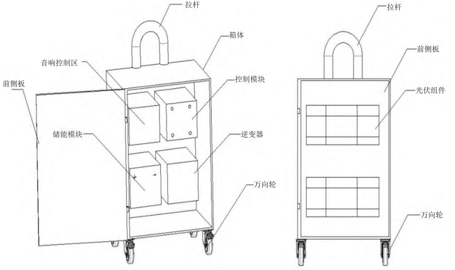
The overall structure of the power supply is shown in Figure 1, which includes a box body, photovoltaic panel components, battery, and inverter. The box body is a pull rod box structure, and the photovoltaic modules are set on the front side panel of the box body that can be opened and closed. The battery and inverter are set inside the box body, and a universal wheel is installed at the bottom of the box body to facilitate the movement of the box body. The photovoltaic modules are connected to the battery, the battery is connected to the inverter, and the inverter is connected to the AC/DC control area on the side panel of the box. The AC/DC control area is also equipped with a main switch, adjustment knob, and display screen to meet the voltage requirements of various electrical devices and expand its applicability. In addition, the power supply also includes a sound module, which is located inside the box and connected to the speakers on the side panel of the box. It has functions such as playing music. The sound control area also has a USB interface, an external memory card interface, and a radio switch. The overall structure of the power supply is compact, lightweight, easy to carry for travel, and convenient to charge; Simultaneously configured reasonably, easy to maintain, with good safety and wide applicability, especially suitable for the use of various electrical appliances during field operations.
2. Modular design
2.1 Box design
The bottom of the box is equipped with a universal wheel that can rotate 360 ° in all directions, making it easy to move, flexible, and labor-saving. It also has a fixing function. The retractable pull rod is made of aluminum alloy material, with a length design not exceeding 80 cm. It is installed on the back of the box, and can be pulled to move the box through the pull rod, making it more convenient to use and carry. It is compact in size and lightweight in structure. The front side panel is connected to the box through hinges to improve solar energy utilization, and it is easy to disassemble and maintain. Fluorescent layers are installed on the upper side panel, front side panel, left side panel, and right side panel of the box, which can emit light at night, making it convenient to use at night and enhancing the convenience of use.
2.2 Design of photovoltaic power generation modules
The photovoltaic module is designed on the front side panel of the box, and the tilt angle can be freely adjusted by the rotation of the front side panel, which can improve the power generation efficiency. The connection method of photovoltaic modules is “2 series and 2 parallel”, which means that the modules are divided into two groups, each containing two photovoltaic panels. Each photovoltaic panel has an output voltage of 12 V and an output power of 36 W. The photovoltaic panels in one group are connected in series and then connected in parallel with another group of photovoltaic panel modules, and then connected to the battery and controller. Photovoltaic modules can charge batteries or directly supply power to external loads under the action of controllers. There is an anti reverse charging diode installed on the connection circuit between the photovoltaic module and the battery, which is connected in series in the solar cell array circuit and has a one-way conduction function to prevent the battery from discharging in the opposite direction to the solar cell array when the solar cell does not generate electricity on rainy days and at night, or when a short circuit fault occurs. The anti reverse charging diode should be able to withstand a sufficiently large current, and the forward voltage drop and reverse saturation current should be as small as possible.
2.3 Energy storage module design
To avoid the inability of mobile power sources to provide electricity when solar cells do not generate electricity on rainy days and at night, the power supply is designed with an energy storage module, namely a battery. The charging end of the battery is connected to the photovoltaic module through a solar charging module and a conversion switch. Under climate conditions, solar power can be used to charge the battery. At the same time, the charging end of the battery is also connected to the mains charging module through a conversion switch, used for charging the battery on rainy and cloudy days and at night. The discharge end of the battery is directly connected to the discharge module. If battery power is required, under the action of the control module, stable DC voltage and 220 V AC mains voltage are output outward. The connection circuit between the battery and the mains charging module is also equipped with anti reverse charging diodes to prevent the battery from discharging in the opposite direction to the mains side.
2.4 Control Module Design
The control module is located inside the box, including a solar charging module, a mains charging module, a discharge module, and a controller. The controller can choose the SNS10A model controller available on the market, using a microcontroller and specialized software. It uses specialized software based on expert control systems to achieve intelligent optimization control. It can have functions such as overcharging, over discharging, electronic short circuit, overload protection, unique anti reverse connection protection, as well as detailed charging indication, battery status, load and various fault indication functions.
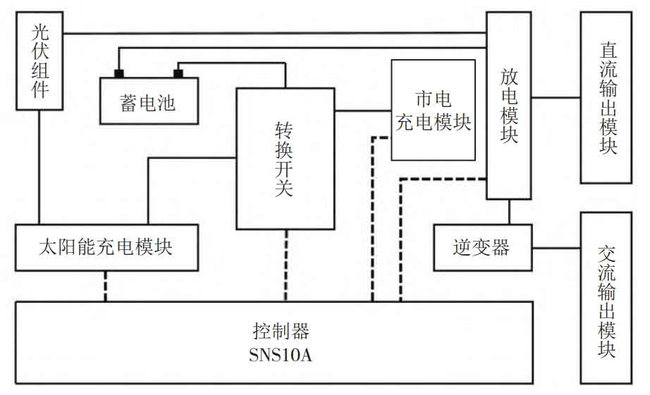
The charging and discharging circuit of the power supply is connected as shown in Figure 2, and the controller is respectively connected to the conversion switch, solar charging module, mains charging module, and discharging module. The output end of the photovoltaic module is connected to the storage charging end through a solar charging module and a conversion switch; The output end of the mains charging module is connected to the battery charging end through a conversion switch and is also connected to the audio control area; One end of the discharge module is connected to the battery output end and photovoltaic module output end through a controller, while the other end is connected to a DC output module and an inverter. The DC output module can directly supply power to the DC load, and the inverter is then connected to the AC output module to supply power to the AC load.
2.5 Other module design
The audio device includes a speaker control area and a connected speaker. The speaker control area is located inside the box and connected to the controller. The speaker is located on the left side panel of the box. The audio control area is equipped with an external memory card interface and radio switch, as well as function keys such as frequency adjustment button, power switch, and volume adjustment button. The controller can control the audio device, play music, receive broadcasts within a certain frequency range, and the speaker can improve the audio effect.
The DC output module is directly connected to the discharge module, equipped with a USB interface and a voltage regulation module, which can provide commonly used levels of DC voltage; The AC output module is directly connected to the inverter and is equipped with a main switch, adjustment knob, display screen, emergency switch, AC switch, and AC interface. The output voltage and current can be adjusted through the knob according to the actual needs of the electrical equipment, expanding the application range.
The display module is directly connected to the controller, including power supply working status indication, battery charging status indication, AC output voltage indication, load indication, and fault indication. Convenient for people to intuitively understand the usage status of the power supply and the charging status of the battery, adjust the AC output voltage, troubleshoot common faults, etc., making the use of the power supply more user-friendly.
3. Working mode
3.1 Working mode of photovoltaic power generation module with separate power supply
When the climate conditions are favorable and the photovoltaic power generation module can generate output power independently to meet the load demand, under the action of the controller, the photovoltaic power generation module provides electricity to the load through the discharge module. The remaining electrical energy is charged to the battery through the solar charging module and used when there is no solar energy. Through the management function of the controller, complementary work between photovoltaic power generation and battery power supply can be achieved, ensuring stable load power supply. The controller detects real-time photovoltaic power generation, battery, and load power, and has the function of switching to the energy storage module for power supply when there is no solar energy or insufficient solar energy.
3.2 Working mode of separate power supply for energy storage modules
When the output power of the photovoltaic power generation module is far less than the load power and cannot meet the demand, the controller automatically switches to the battery power supply state, and provides stable AC/DC output to the load through the discharge module and inverter control unit. In this mode, the battery ensures continuous and stable power supply to important loads. Similarly, the controller can detect photovoltaic power generation, batteries, and load power in real-time, and has the function of switching to photovoltaic power generation modules for power supply when solar energy is sufficient.
3.3 Working mode of joint power supply between photovoltaic power generation module and energy storage module
When the output power of the photovoltaic power generation module is insufficient but the gap is small, under the action of the controller, it automatically switches to the joint power supply mode of the photovoltaic power generation module and the battery. In this mode, the photovoltaic power generation module and energy storage module jointly supply power to the load, ensuring that the output power of the photovoltaic power generation and the output power of the battery are greater than or equal to the load power. The controller can detect photovoltaic power generation, battery, and load power in real time, switch to separate power supply of photovoltaic power generation module when solar energy is sufficient, and switch to separate power supply mode of energy storage module when solar energy is severely insufficient.
During this process, the control module can detect real-time data and parameters of power supply operation, understand real-time control status, ensure timely switching of working status when conditions change, and improve power supply reliability and stability.
4. Conclusion
Solar powered portable mobile power sources have advantages such as no fuel consumption, no noise, no pollution, energy conservation, and environmental protection, avoiding most of the problems of ordinary portable mobile power sources. But currently there are also technical problems that are difficult to solve. Firstly, the switching of the three working modes is not sensitive enough and not smooth enough, and there are sudden changes or delays during switching; Secondly, although the installation of universal wheels makes the overall movement of the power supply convenient, due to its rich functions, there are many modules and complex structures, resulting in a larger overall volume of the power supply. In the later stage, we will focus on researching the optimization of work mode switching and the miniaturization of modules and components, aiming to achieve achievement transformation as soon as possible.