
In my experience as an engineer specializing in renewable energy applications, designing off-grid solar systems for mobile platforms like tourist ships presents unique challenges and opportunities. The increasing demand for eco-friendly tourism has driven the adoption of sustainable power solutions, and off-grid solar systems offer a viable alternative to traditional fossil fuel-based generators. This article details the comprehensive design process for an off-grid solar system aimed at achieving zero loss-of-load probability, ensuring reliable power for all non-propulsion electrical loads on tourist vessels. I will explore key aspects such as photovoltaic array orientation, system sizing, and component selection, supported by mathematical models and practical examples. Throughout this discussion, the term “off-grid solar system” will be emphasized to underscore its importance in achieving energy independence and environmental sustainability.
The core motivation for implementing an off-grid solar system on tourist ships stems from the need to reduce pollution and operational costs. Typically, auxiliary power on these vessels is supplied by diesel generators, which incur high fuel expenses and emit pollutants that harm aquatic ecosystems. By harnessing solar energy, we can create a clean, renewable power source that aligns with the scenic and environmental values of tourist destinations. An off-grid solar system operates independently of the grid, making it ideal for mobile applications where grid connection is impractical. In this design, I focus on a fixed installation on ship decks, considering factors like safety, aesthetics, and energy efficiency. The goal is to ensure that the off-grid solar system meets daily energy demands without fail, even under varying weather conditions.
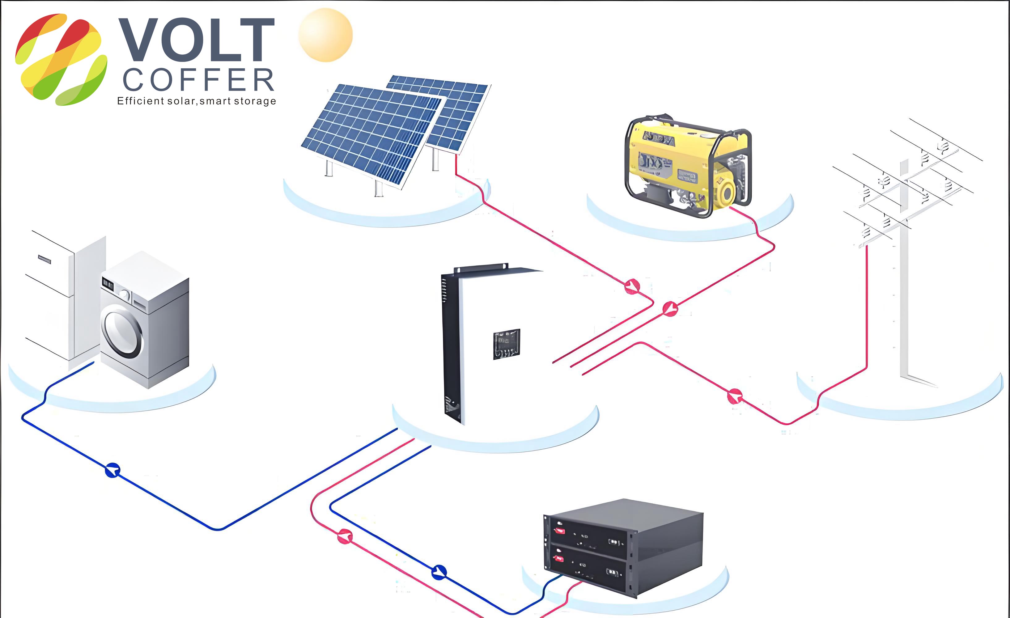
The structure of an off-grid solar system for a tourist ship includes several key components: photovoltaic panels, a charge controller, batteries, an inverter, and the electrical loads. The photovoltaic panels convert sunlight into electricity, serving as the primary energy source. The charge controller regulates the charging and discharging of the batteries to prevent overcharging or deep discharge, thereby extending battery life. Batteries store the generated energy for use during periods of low solar insolation, such as at night or on cloudy days. The inverter converts the stored DC power to AC power to run common appliances like air conditioners, lighting, and communication devices. This integrated off-grid solar system ensures a continuous power supply while minimizing environmental impact. Below is a summary of the design steps involved in configuring such a system:
| Step | Description |
|---|---|
| 1 | Analyze solar resource data for the operating region |
| 2 | Determine daily load energy consumption |
| 3 | Select system DC voltage based on load requirements |
| 4 | Calculate photovoltaic array tilt angle and orientation |
| 5 | Size the photovoltaic array capacity |
| 6 | Size the battery storage capacity |
| 7 | Select appropriate charge controller and inverter |
One critical aspect of designing an off-grid solar system for a tourist ship is the analysis of the photovoltaic array’s tilt angle. Since the ship is mobile, its orientation changes frequently, making fixed tilt angles less effective. In my approach, I consider the array as horizontally placed for simplicity, as this minimizes complexity and aligns with safety constraints. The total solar radiation incident on a horizontal surface, denoted as \( Q_p \), is the sum of direct radiation \( S_p \) and diffuse radiation \( D_p \), expressed as:
$$ Q_p = S_p + D_p $$
For a tilted surface, the total radiation \( Q_T \) includes direct radiation \( S_T \), diffuse radiation \( D_T \), and reflected radiation \( R_T \), given by:
$$ Q_T = S_T + D_T + R_T $$
However, due to the ship’s movement, the azimuth angle varies continuously, so I approximate the radiation on a tilted array as 90% of that on a horizontal surface. This simplification ensures conservative design estimates for the off-grid solar system. The coefficient for converting horizontal direct radiation to tilted direct radiation, \( R \), depends on the tilt angle \( \beta \) and is calculated as:
$$ R = \frac{\cos(\theta)}{\cos(\theta_z)} $$
where \( \theta \) is the angle of incidence on the tilted surface and \( \theta_z \) is the zenith angle. Given the dynamic nature of ships, I recommend using horizontal radiation data for initial sizing of the off-grid solar system to avoid overestimation.
Moving to system capacity design, the first step is to analyze the daily energy consumption of the loads. Tourist ships typically have non-propulsion loads such as air conditioning, television, lighting, and communication systems. The total daily energy demand \( P_F \) in watt-hours (Wh) is calculated as:
$$ P_F = \sum_{i=1}^{n} p_i \times h_i $$
where \( p_i \) is the rated power of load type \( i \) in watts, and \( h_i \) is its daily operating hours in hours. For instance, if a ship has multiple loads, their contributions are summed to determine the overall energy requirement. This value is crucial for sizing the off-grid solar system components accurately. Next, the system DC voltage \( V_Z \) is selected to minimize power losses. Based on standard DC voltage levels, I typically choose 48 V for such applications, as it balances efficiency and safety. The photovoltaic array must then be sized to meet the daily energy demand. The charging current required from the array \( I_{ZJ} \) in amperes is given by:
$$ I_{ZJ} = \frac{P_F \times \eta_1}{V_Z \times T_D \times \eta_2 \times \eta_3} $$
where \( \eta_1 \) is the solar panel degradation factor over 20 years (typically 1.02), \( \eta_2 \) is the inverter efficiency (assumed 0.8), \( \eta_3 \) is the battery charging efficiency (assumed 0.9), and \( T_D \) is the peak sun hours in hours per day. The peak sun hours are derived from solar radiation data, where \( T_D = Q’ \times 3.6 \), with \( Q’ \) being the daily solar radiation in MJ/m². To ensure zero loss-of-load, I use the minimum monthly radiation data for design, guaranteeing reliability even in the worst-case scenario.
The photovoltaic array configuration involves determining the number of series-connected panels \( N_C \) and parallel-connected panels \( N_B \). For a panel with peak voltage \( V_m \) and peak current \( I_m \), the series count \( N_C \) is set to match the battery floating charge voltage \( V_F \), considering temperature and wiring losses:
$$ N_C V_m = V_F = V_f + V_t + V_d $$
where \( V_f \) is the base floating voltage, \( V_t \) is the voltage drop due to temperature, and \( V_d \) is the wiring loss. The parallel count \( N_B \) is calculated based on the charging current:
$$ N_B I_m = I_{ZJ} $$
Thus, the total array power \( P_{ZJ} \) in watts is:
$$ P_{ZJ} = N_B I_m \times N_C V_m $$
For battery sizing, the capacity \( C \) in ampere-hours (Ah) is determined to store sufficient energy for autonomy during low-sun periods. The formula accounts for discharge depth and efficiency:
$$ C = \frac{P_F \times F \times D}{V_Z \times L \times U} $$
where \( F \) is the battery discharge efficiency correction factor (1.05), \( D \) is the number of autonomy days (e.g., 2 days for tourist ships), \( L \) is the battery maintenance factor (0.8), and \( U \) is the depth of discharge (0.5). This ensures the off-grid solar system can sustain loads during extended cloudy weather. Component selection follows these calculations. The charge controller must handle the array’s current and voltage, while the inverter is chosen based on the load power and type, with allowances for surge currents.
To illustrate, I will present a generalized example based on a tourist ship in a temperate region. Suppose the minimum monthly solar radiation occurs in January, with an average daily radiation of 8 MJ/m². This corresponds to peak sun hours \( T_D = 8 \times 3.6 = 2.88 \) hours. The daily load consumption is summarized in the table below:
| Load Type | Rated Power (W) | Operating Hours (h) | Daily Energy (Wh) |
|---|---|---|---|
| Air Conditioning | 1500 | 6 | 9000 |
| Lighting | 200 | 10 | 2000 |
| Television | 100 | 4 | 400 |
| Communication | 50 | 24 | 1200 |
| Total | 1850 | – | 12600 |
Thus, \( P_F = 12600 \) Wh. Using a system voltage \( V_Z = 48 \) V, the daily load in ampere-hours \( I_D \) is:
$$ I_D = \frac{P_F}{V_Z} = \frac{12600}{48} = 262.5 \, \text{Ah} $$
Assuming photovoltaic panels with \( V_m = 36 \) V and \( I_m = 5.082 \) A, the series count \( N_C \) is 2 to achieve approximately 72 V, accounting for losses. The charging current \( I_{ZJ} \) is:
$$ I_{ZJ} = \frac{12600 \times 1.02}{48 \times 2.88 \times 0.8 \times 0.9} = \frac{12852}{99.5328} \approx 129.1 \, \text{A} $$
Then, the parallel count \( N_B \) is:
$$ N_B = \frac{I_{ZJ}}{I_m} = \frac{129.1}{5.082} \approx 25.4 \rightarrow 26 \, \text{panels} $$
The total array power is \( P_{ZJ} = 26 \times 2 \times 180 = 9360 \) W, but to meet the demand, we adjust based on practical panels. For batteries, the capacity \( C \) is:
$$ C = \frac{12600 \times 1.05 \times 2}{48 \times 0.8 \times 0.5} = \frac{26460}{19.2} \approx 1378.125 \, \text{Ah} $$
Rounding up, we select a 1400 Ah battery bank at 48 V. This off-grid solar system design ensures that energy needs are met reliably. The charge controller should handle 130 A at 48 V, and the inverter must support at least 2000 W continuous power with surge capability for motor loads.
In conclusion, designing an off-grid solar system for tourist ships involves meticulous planning to achieve zero load loss. The initial investment, though substantial, is offset by long-term savings and environmental benefits. For instance, the cost of energy from an off-grid solar system can be as low as $0.16 per kWh over 20 years, compared to $0.20 for diesel generation. Moreover, the reduction in carbon emissions and water pollution aligns with global sustainability goals. Future improvements could integrate hybrid systems combining solar with backup generators to optimize costs and reliability. Through this detailed approach, the off-grid solar system proves to be a robust solution for eco-friendly tourism, emphasizing the importance of renewable energy in mobile applications.
Reflecting on this process, I find that the key to a successful off-grid solar system lies in accurate solar resource assessment and conservative component sizing. By prioritizing worst-case scenarios, we can build resilient systems that operate efficiently across varying conditions. The mathematical models and tables provided here serve as a foundation for custom designs, and I encourage further experimentation with different configurations to enhance performance. As technology advances, the efficiency of photovoltaic panels and batteries will improve, making off-grid solar systems even more accessible and cost-effective for maritime use.