
1. Design background
In the process of wind farm construction, due to factors such as wind turbine grid connection procedures and grid connection, it is often necessary to wait for a long period of time before grid connection debugging can be carried out after the completion of wind turbine installation work. If this period of time is prolonged, the wind turbine debugging work will remain stagnant for a long time, causing serious waste of time and management costs. Therefore, by using better power supply solutions, the construction period of the entire wind farm construction project will be greatly shortened, enabling wind turbines to achieve power generation and grid connection as soon as possible, effectively improving the overall power generation efficiency of the wind farm.
The debugging of fans can be divided into two types: static debugging and dynamic debugging. Static debugging refers to the wind turbine being in a non generating state, and the debugging power of the wind turbine is provided by external equipment. Dynamic debugging refers to the wind turbine being in a grid connected power generation state, when the wind turbine sends electrical energy to the outside.
To meet the bidirectional flow of energy during both static and dynamic debugging of the wind turbine, a mobile battery energy storage system has become a feasible solution.
2. Control system
The mobile battery energy storage system can be used for local and remote black start and grid connection debugging of a single wind turbine when the wind farm is not powered on. At the same time, it is also equipped with a DC charging station, which can serve as a mobile charging bank for emergency charging of new energy electric vehicles in the wind farm. The mobile battery energy storage system consists of a lithium iron phosphate battery pack, energy storage converter, battery management system, fire protection system, thermal management system, auxiliary control system, and standard energy storage container.
The debugging of mobile battery energy storage systems in wind farms can be divided into local mode and remote mode. In local mode, it can be divided into battery charging mode, static debugging mode, dynamic debugging mode, and electric vehicle charging mode. In remote mode, the mobile battery energy storage system outputs an AC 690V power supply, which is boosted through a wind farm step-up transformer and then transmitted to the remote wind turbine or power grid by the power grid.
(1) Battery charging mode. The 400V power supply of the power grid is connected to the charging interface of the mobile battery energy storage system. The system control mode selects the battery charging mode, and the energy storage converter starts at zero voltage ramp in grid connection mode. At this time, the power grid charges the energy storage battery. When the charging state of the energy storage battery reaches the set value, that is, the charging state of the energy storage battery is not less than 90%, the system automatically stops working.
(2) Static debugging mode. The system control mode is selected as static debugging mode. When the tested fan blades are in a locked state, the output power of the energy storage converter is set to meet the required power for fan debugging. The energy storage converter starts at zero voltage ramp in off grid mode and outputs an AC 400V power supply.
(3) Dynamic debugging mode. The system control mode selects dynamic debugging mode. When the wind turbine is in a grid connected state, the input power of the energy storage converter is set to be greater than the output power of the wind turbine converter. The energy storage converter starts at zero voltage ramp in off grid mode, and the electricity generated by the doubly fed asynchronous generator of the wind turbine is absorbed by the energy storage battery.
(4) Electric vehicle charging mode. The system control mode selects the electric vehicle charging mode, and the energy storage converter starts at zero voltage ramp in off grid mode. The system outputs an AC 400V power supply to a 30kW wall mounted DC charging station, and then converts the output of a 200-750V DC power supply to provide emergency charging for electric vehicles in the wind farm.
(5) Remote debugging mode. After the construction of the wind farm is completed, during the grid connection procedures, remote power supply can be achieved through a mobile battery energy storage system, which can greatly save the debugging time of the entire project by providing remote power supply debugging for wind turbines in different areas of the wind farm. The system control mode selects remote debugging mode. The energy storage converter starts at zero voltage ramp in off grid mode, and the system outputs 690V AC power to the wind farm step-up transformer, which is then transmitted to the remote wind turbine to be debugged through the power grid.
3. Communication network
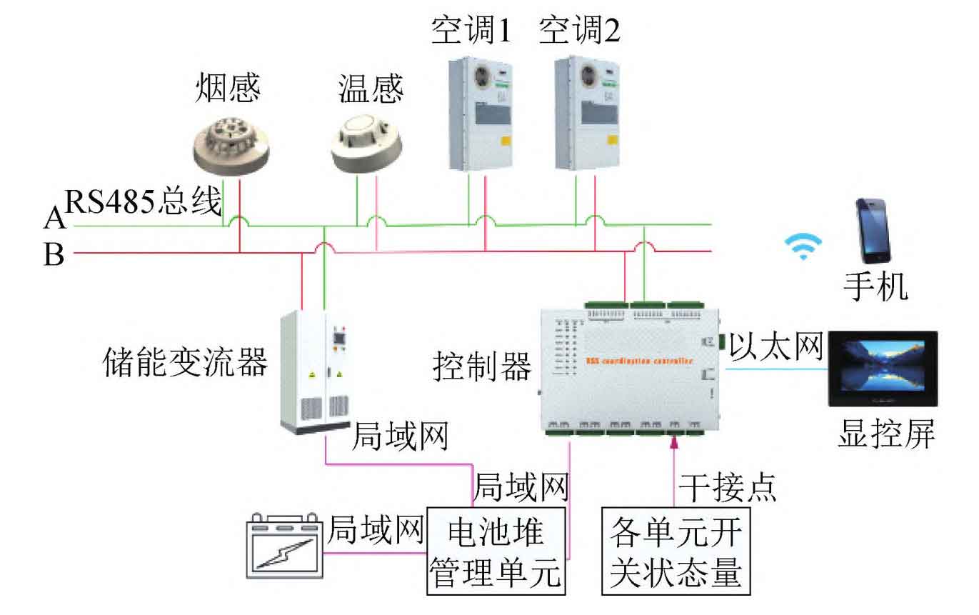
As the control brain of the mobile battery energy storage system, the local controller is mainly used to collect real-time information of energy storage batteries, energy storage converters, fire protection systems, thermal management systems, and various units. After summarizing the equipment information of each unit, it is uploaded to the local monitoring platform and cloud platform. The role of the local monitoring platform is to manage the start stop logic of each energy storage subsystem, process system protection logic, and allocate energy storage power. The role of the cloud platform is as follows: When wind farm debugging personnel work inside the wind turbine tower, they can monitor the operation status and battery charge status of the mobile battery energy storage system in real-time through mobile applications. The system network communication architecture is shown in Figure 1.
4. Thermal management system
In the mobile battery energy storage system, only lithium iron phosphate batteries have relatively strict working environment requirements, with a working temperature range of 25 ℃ ± 5K. The battery room is an independent enclosed space. From a cost perspective, the system network communication architecture shown in Figure 1 can only be configured with a cooling and heating system in the battery room.
The design of the indoor temperature control system of the battery directly determines the working performance and efficiency of the lithium iron phosphate battery pack, and also affects the battery cycle life and safe operation of the battery. Therefore, the reasonable selection of equipment is a decisive factor for the safe, stable, and reliable operation of energy storage systems.
(1) Cooling power calculation. The calculation of cooling power Pc mainly considers two factors: the power consumption, heating power PR, and external static infiltration heat P1 of the battery.
The power consumption and heating power PR of the battery can be determined by the total capacity E of the battery, the rated working current rate C, and the overall charging and discharging cycle efficiency of the battery μ To estimate, the calculation formula is:

When energy storage containers are placed outdoors, due to the influence of external environmental temperature, external static infiltration heat P1 will be generated in the interior of the battery. The heat value is related to the effective heat transfer coefficient K and surface area of the energy storage container surface. The calculation formula is:

In the formula: St is the area of the top of the energy storage container; Sc is the total area of the four side walls of the energy storage container; Sb is the area at the bottom of the energy storage container; Kt is the effective heat transfer coefficient at the top of the energy storage container; Kc is the effective heat transfer coefficient on the side of the energy storage container; Kb is the effective heat transfer coefficient at the bottom of the energy storage container; Δ T is the temperature difference between the outside and inside of the container.
From equations (1) and (2), it can be concluded that the cooling power Pc is:

In the formula, K is the correction factor, and the general value range is 1.2~1.5.
(2) Calculation of heating power. When the mobile battery energy storage system starts up in winter, it needs to heat the space in the battery room. The required heating capacity Qh depends on the static temperature t1, heating time T0, starting temperature t0, and the power P2 to compensate for the static heat leakage from the box during the heating period. The calculation formula is:
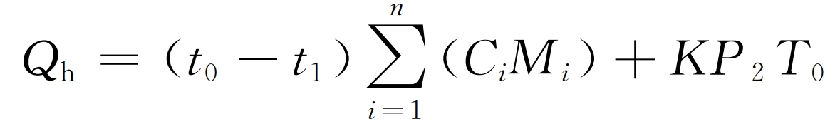
In the formula, Ci is the specific heat capacity of the i-th component; Mi is the mass of the i-th component; N is the number of components.
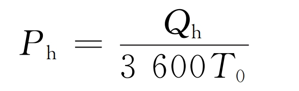
Therefore, it can be concluded that the heating power Ph is:
5.Temperature control strategy
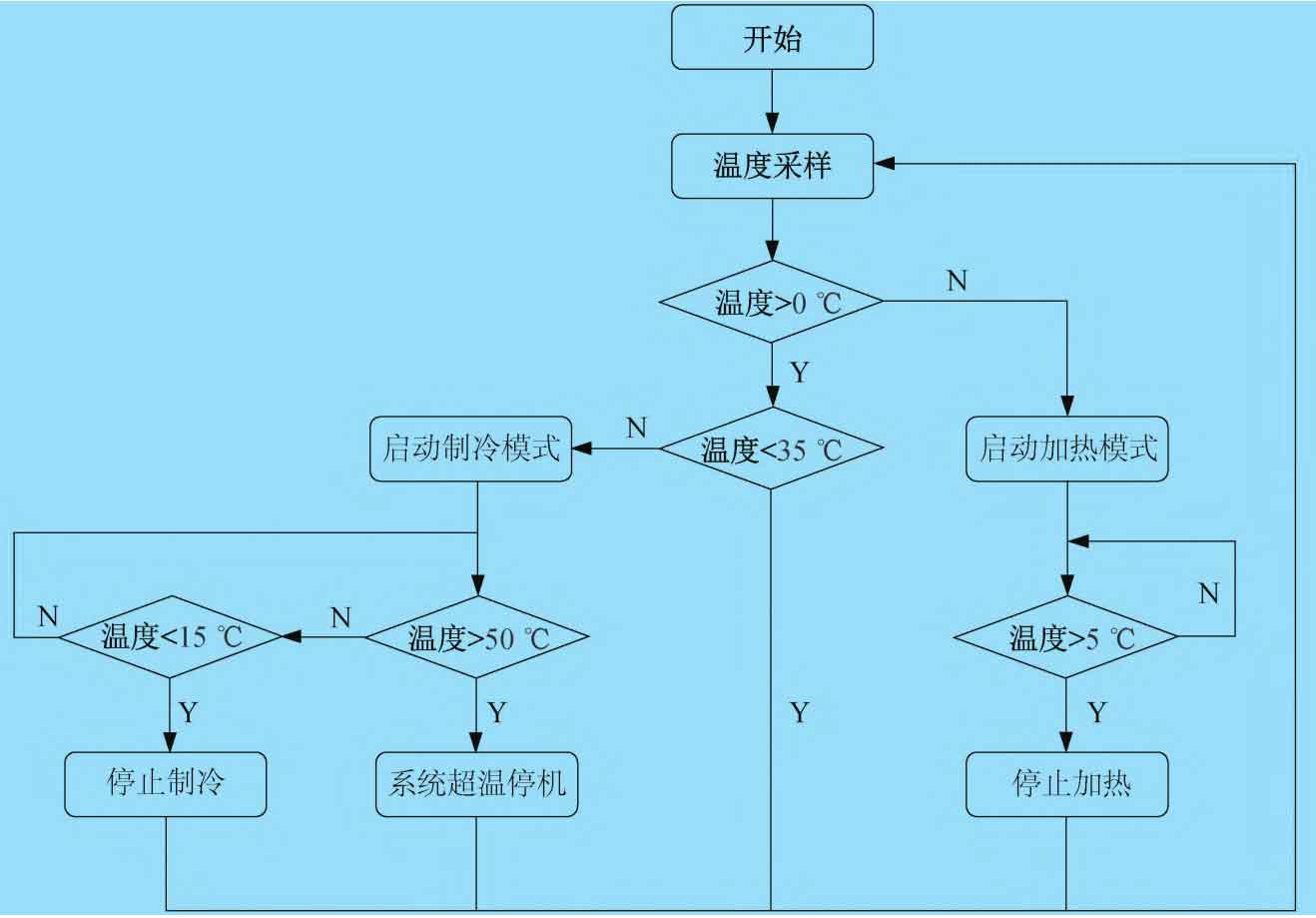
The temperature control strategy of the mobile battery energy storage system is divided into heating mode and cooling mode. The heating mode controls and protects the battery at low temperatures, while the cooling mode effectively controls the temperature rise of the battery. The temperature control logic is shown in Figure 2.
6. Fire protection system
The operation of lithium iron phosphate batteries in the battery room is relatively closed, with limited heat dissipation conditions. During the charging and discharging process, lithium iron phosphate batteries are prone to heat accumulation, especially in extreme operating conditions such as overcharging, short circuit, overheating, etc. Heat accumulation can easily lead to a sharp increase in battery temperature and thermal runaway, leading to fire and explosion accidents of lithium iron phosphate batteries.
Therefore, in addition to designing heat dissipation and refrigeration for energy storage containers, it is also necessary to design a reasonable fire protection system for energy storage containers to improve the safety of their operation. Based on the internal structure and fire hazards of the battery room, the author adopts a cabinet type heptafluoropropane gas fire extinguishing system. It is a colorless, odorless, non-conductive, and non secondary pollution gas with the characteristics of clean, low electrical insulation, and high fire extinguishing efficiency. The fire protection system is shown in Figure 3.
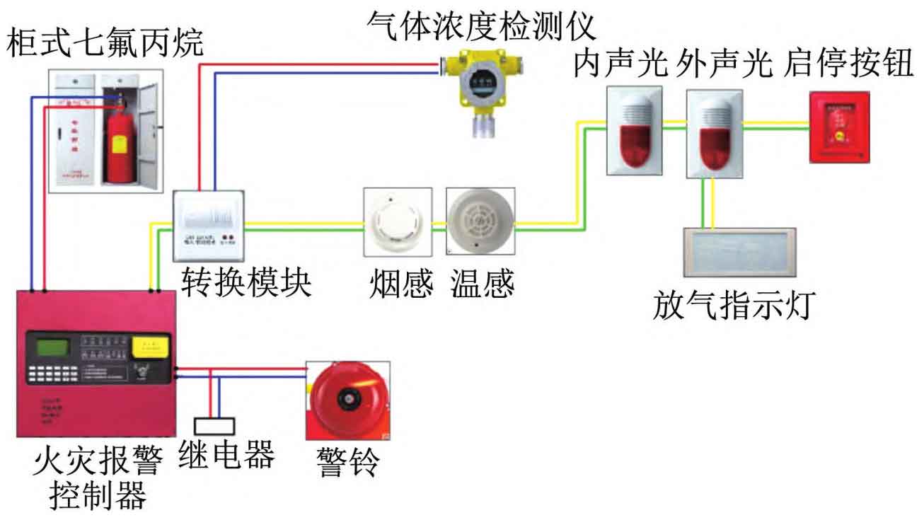
The control room and transformer room have complete overheating protection, short circuit protection, etc. Fire is a very extreme working condition, and there is a smoke sensor in the cabin. Once an alarm signal is detected, the system will shut down and shut down. Therefore, carbon dioxide fire extinguishers can be used as backup fire extinguishers in the control room and transformer room.
7.Energy storage container
Most wind farms in China are located in remote areas, with harsh climate and environmental conditions. Especially in northern wind farms, which are mostly located in plateau areas, a considerable portion of wind farms have elevations above 1800m, and the lowest winter temperature is below -30 ℃. In addition, most of the roads before entering the wind farm are rugged mud or mountain roads, so the strength and insulation design of energy storage containers directly affect the safe and efficient use of mobile battery energy storage systems.
7.1 Box strength and anti-corrosion design
As the carrier of the entire mobile energy storage system, energy storage containers are subject to force majeure during transportation, uncontrollable transportation conditions, and human factors that require them to have a sufficiently sturdy structure and strength.
Energy storage containers can be made of steel, characterized by high strength, firm structure, good weldability, and water tightness. In terms of structure, the frame and bottom beam of the energy storage container are made of weather resistant steel plates with a thickness of no less than 2.5mm, while the box and top are made of corrugated steel plates with a thickness of no less than 1.5mm. In terms of anti-corrosion, energy storage containers are designed with a lifespan of 25 years and treated with high weather resistance and anti-corrosion technology.
7.2 Box insulation design
The insulation of a mobile energy storage system mainly depends on the design of the energy storage container. The better the insulation performance of the container, the smaller the impact of the external environment on the temperature inside the container. Through research, there are two main factors that affect the insulation effect of energy storage containers, one is insulation, and the other is sealing. In terms of insulation, efficient insulation materials with low thermal conductivity should be used as much as possible, and a double-layer insulation material scheme should be adopted to improve the overall insulation effect. That is, the inner walls of the six sides of the energy storage container body should be sprayed with a composite A-grade fireproof polyurethane with a thickness of 50mm and a thermal conductivity of 0.025 W/(m · K), and then covered with an A-grade fireproof insulation rock wool board with a thickness of 50mm and a thermal conductivity of 0.044 W/(m · K), The combination of two materials can effectively improve the insulation performance of the cabin. In terms of sealing, the protection level is mainly improved by using EPDM sealing strips for the box door and filtering cotton for the louvers. Generally, the protection level cannot be lower than IP54.
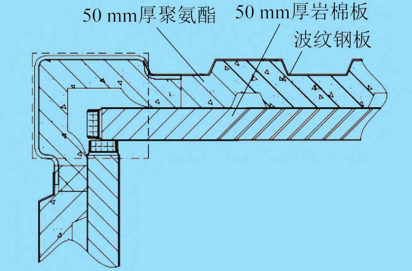
The insulation layer design of the energy storage container is shown in Figure 4.
7.3 Overall layout
The mobile battery energy storage system adopts standard energy storage containers, and the internal layout of the containers is divided into three compartments: battery room, control room, and transformer room. The control room and battery room are isolated through safety doors, and the control room and transformer room are isolated through a partition firewall.
The battery room is equipped with lithium iron phosphate battery clusters, thermal management systems, and cabinet type heptafluoropropane fire extinguishing devices. The control room is equipped with distribution control cabinets, energy storage converters, and fire engines. The transformer room is equipped with transformers, charging stations, and cable interface systems.
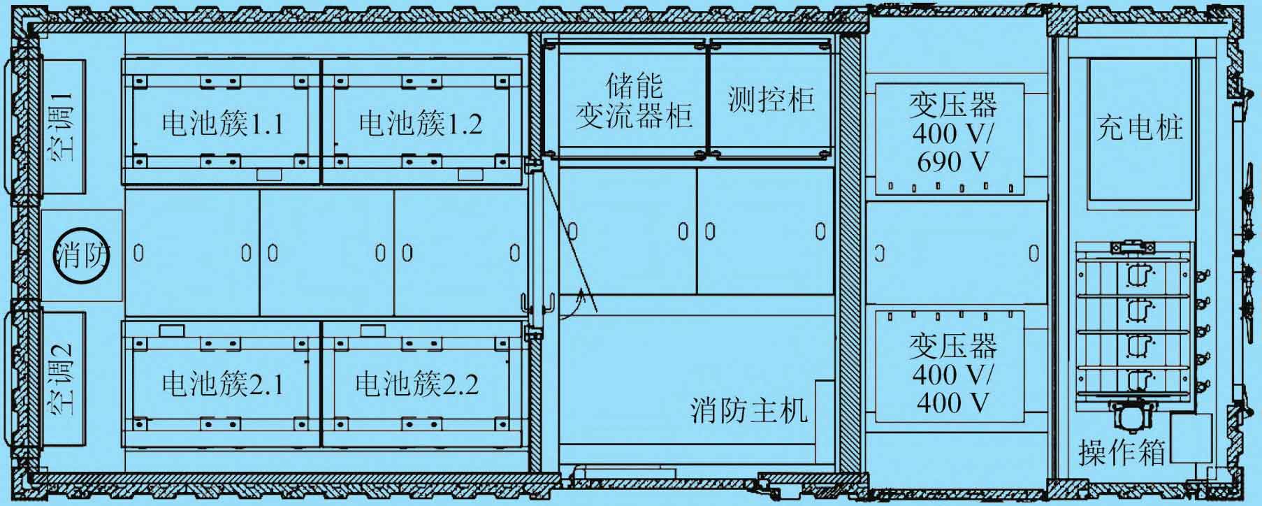
The internal layout of the energy storage container is shown in Figure 5.
8. Technical advantages
(1) Compared with traditional diesel generators, the mobile battery energy storage system has the characteristics of millisecond response, zero power supply flicker, off grid black start, and high efficiency, thereby ensuring the stability and reliability of the debugging power supply.
(2) The mobile battery energy storage system has the characteristic of bidirectional energy flow, and can simultaneously charge the energy storage battery during the dynamic debugging process of the fan. The entire debugging process can achieve zero consumption and zero emissions.
(3) The mobile battery energy storage system has unique control algorithms and reasonable transmission system parameters, which can avoid sub synchronous resonance between the doubly fed wind turbine and the mobile battery energy storage system in weak current grid environments.
9. Conclusion
Mobile battery energy storage systems have become an important branch of energy storage systems due to their excellent power storage and transmission performance, high reliability and safety, as well as outstanding flexibility and mobility. Their applications have covered areas such as power emergency repair, road rescue, power maintenance for important conferences, power capacity expansion, and uninterrupted operation. With the continuous expansion of market-oriented applications and technological progress, mobile battery energy storage systems are bound to become an important technology industry in the energy internet in the future.