
Solar energy, as a clean energy source, has been widely used in people’s lives, and solar street lights are one of them. They can be found on both sides of bustling urban roads or on remote mountain roads. The principle of solar street lights: The solar panel is responsible for converting solar energy into electrical energy, which is stored in a battery through a charging device. The electrical energy control device controls the on and off of the circuit, thereby controlling the on and off of the street lights, and ultimately completing the conversion of solar energy to light energy.
The technology of solar street lights has developed very maturely. Compared with traditional street lights, solar street lights do not need to consider the issue of long-distance power transmission. They can generate electricity in areas with the sun, which has obvious advantages; The disadvantage is that the power generation is greatly affected by weather. If encountering continuous rainy weather, solar energy devices cannot replenish electricity in a timely manner, resulting in no electricity available. In response to these issues, solar street light controllers with time-based control and sensor based sound and light control have emerged. These technological means can indeed save energy and prolong the lighting time of street lights, but the utilization rate of electricity is not high.
In order to save electricity and improve the utilization efficiency of solar street light energy, the existing solar street light system has been renovated. Design a solar street light adaptive energy-saving device that can adaptively adjust the electricity output according to future weather conditions and remaining battery power, while improving the efficiency of electricity utilization.
1. System design scheme
The system design starts from the perspective of energy conservation, with economic practicality as the premise, and innovatively designs on the existing solar street light system.
The energy-saving device is connected in series between the “solar street light battery” and the “street light”, mainly composed of a weather acquisition module, an electricity collection module, an LED driver, and an MCU controller. The functions of each part are as follows.
(1) Weather acquisition module. This module serves as a bridge between the system and the weather forecast website, and is the core innovation point of energy-saving devices. The system can obtain weather conditions in advance through the weather acquisition module.
(2) Electricity collection module. Monitor the remaining power of the battery to prevent over discharge and extend its service life; Provide data support for the street lighting scheme based on weather forecasts.
(3) LED driver. LED bead strings are used for street lights, and the power of the street lights is controlled through LED driving devices.
(4) MCU controller. It is the algorithm control center of energy-saving devices, whose main functions include: ① obtaining data through the weather acquisition module and conducting analysis and processing; ② Obtaining the power of the battery through resistance voltage division, converting it into digital signals through ADC and storing them; ③ Use the PWM function of the port to control the LED driving device, thereby controlling the instantaneous power of the street lights; ④ Based on the weather and remaining electricity, use algorithms to determine the optimal lighting scheme.
This energy-saving device connects to the internet to obtain information on weather and battery power, and makes the best lighting plan in advance, reflecting its adaptability to the weather environment.
2. Hardware design
2.1 MCU controller
The MCU controller is the control center of the entire system, and the model of the control chip is determined based on task requirements and cost-effectiveness. Specific requirements: One ADC completes battery level detection; 1 PWM circuit to control the LED drive circuit; One serial port obtains weather conditions through networking. STC15W401AS is selected here, packaged in the form of SOP16, with a working voltage of 2.5-5.5 V. It has ADC, PWM, and serial port functions, high cost-effectiveness, and meets design requirements.
2.2 Weather acquisition module
The weather acquisition module is the basis for the adaptive decision-making of the system’s energy-saving control. The main function is to connect the system to the internet. The ATK-ESP8266 WiFi module uses a serial port (LVTTL) to communicate with the MCU (or other serial devices), with a built-in TCP/IP protocol stack that can achieve conversion between serial ports and WiFi. This module supports three modes: serial wireless AP, serial wireless STA, and serial wireless AP+STA. Each mode includes three sub modes: TCP server, TCP client, and UDP. The microcontroller is connected to the WiFi module through a serial port, connected to the router through AT commands, and then connected to the internet through the router to obtain real-time time and weather conditions.
2.3 LED driver
The function of the electric energy control module is to manage the effective output of the battery based on weather forecasts and remaining battery energy. The XLT604 power LED driver control chip is used here, and the input voltage can effectively drive high brightness LEDs with a constant current between 8-450VDC. The constant current range can reach 5 mA to 1 A, and the maximum number of LED drives can reach 100. The control methods include external voltage control and external low-frequency PWM control. External low-frequency PWM control is selected here. The microcontroller outputs PWM waves based on electricity and weather conditions to control electrical energy. A typical application circuit is shown in Figure 1.
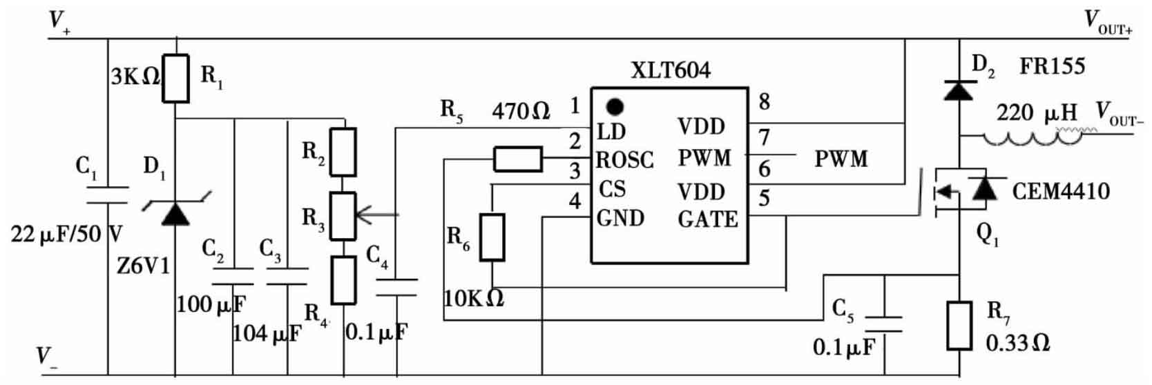
This circuit diagram shows a typical input voltage of 10-30 V, output LED bead string voltage of 7-24 V, maximum current of 400 mA, external voltage control, by adjusting the voltage loaded on the LD port to change the output current. When the voltage on the LD is greater than 250 mV, the output current is not affected; PWM adjustment method, adding a PWM signal of several hundred Hz to the 7-pin PWM port. At this time, the positive voltage width of the LED is proportional to the brightness of the LED light. By adjusting the PWM pulse width, the output current can be controlled between 0-400 mA for arbitrary adjustment.
2.4 Battery Energy Monitoring
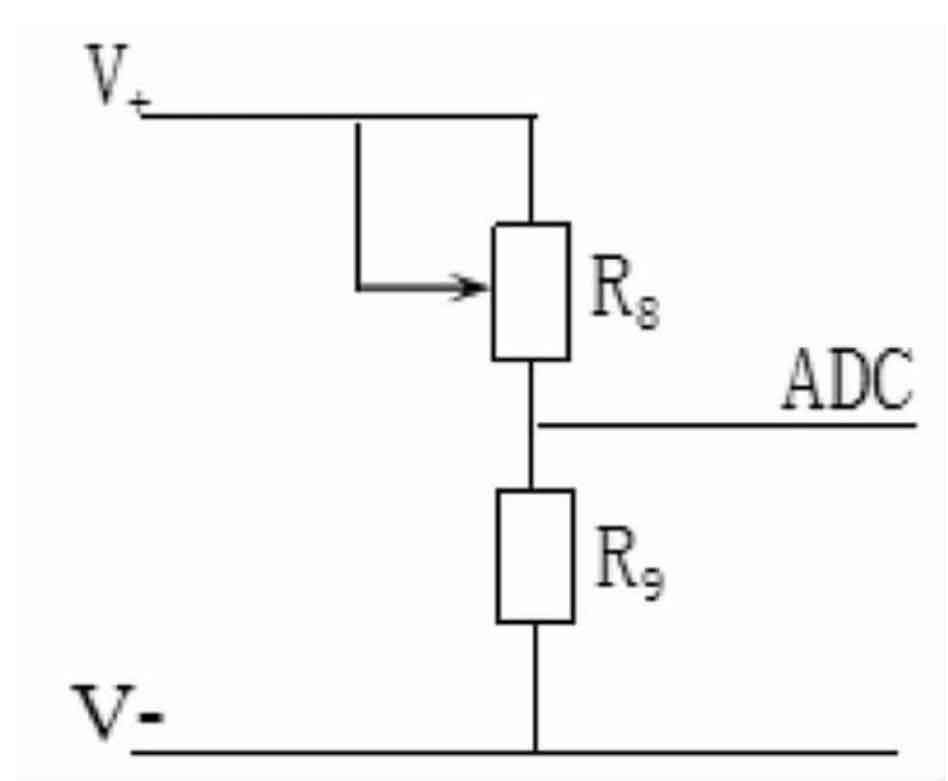
The electrical energy monitoring of the battery is completed through a resistance voltage divider circuit. The battery’s power is sampled and converted into a linear voltage signal that can be recognized by the 0-5 V microcontroller ADC port based on voltage, which can be used for battery energy monitoring. The voltage divider circuit is shown in Figure 2. In Figure 2, R8 and R9 are voltage divider circuits composed of resistors in units of M. After connecting to the battery, the voltage divider circuit converts the battery voltage into a voltage that can be recognized and tested by the microcontroller ADC. The debugging method is to adjust potentiometer R8 so that the voltage at the ADC port is 5 V when the battery is at 100% charge.
3. Software design
3.1 Control Strategy
Control process: The MCU controller obtains the weather situation through the weather acquisition module, obtains the battery power through the voltage divider circuit, and makes the corresponding optimal control plan through comprehensive calculation. Taking the 25 WLED bulb as the analysis object, the brightness of the LED light is set to three levels: on (25 W), medium (17 W), and dark (8 W) by controlling the pulse width of PWM. The control period and estimated power consumption are calculated, as shown in Table 1.
| Plan number | Brightness | Starting time period | Estimated electricity consumption/kWh |
| Option 1 | Bright | Summer: 19:00-22:00; Winter: 18:00-21:00 | Summer: 0.159 Winter: 0.167 |
| Option 1 | Mid | Summer: 22:00-24:00; Winter: 21:00-23:00 | Summer: 0.159 Winter: 0.167 |
| Option 1 | Dark | Summer: 00:00-05:00; Winter: 23:00-05:00 | Summer: 0.159 Winter: 0.167 |
| Option 2 | Mid | Summer: 19:00-24:00; Winter: 18:00-23:00 | Summer: 0.125 |
| Option 2 | Dark | Summer: 00:00-05:00; Winter: 23:00-05:00 | Winter: 0.133 |
| Option 3 | Dark | Summer: 19:00-05:00; Winter: 18:00-05:00 | Summer: 0.80; Winter: 0.88 |
| Option 4 | Dark | Summer: 19:00-24:00; Winter: 18:00-23:00 | Summer: 0.04; Winter: 0.0 |
From Table 1, it can be seen that the lowest power consumption is Scheme 4, with a lighting time of 5 hours. During the summer from 19:00 to 24:00, the power consumption is only 0.04 kWh. If the solar street light battery is 12 V 60 A, then a fully charged battery can theoretically store 0.72 kWh of electrical energy. Considering the impact of charging and discharging on the battery life, it is set to turn off the street lights when the remaining power is less than 30%. Based on the minimum plan 4, it is estimated that continuous rain and rain can reach 12.5 days, and the system power consumption is also above 10 days. If a larger battery is replaced, the service life will be longer. The control system should adopt a comprehensive consideration based on real-time weather conditions and remaining electricity. The specific control strategy is shown in Table 2.
| Remaining power | 4-day continuous cloudy and rainy weather | 3-day continuous cloudy and rainy weather | 2-day continuous cloudy and rainy weather | 1-day continuous cloudy and rainy weather | No continuous rainy weather |
| ≥ 85% | Scheme 4 | Scheme 3 | Scheme 2 | Scheme 1 | Scheme 1 |
| ≥ 70% | Scheme 4 | Scheme 3 | Scheme 3 | Scheme 2 | Scheme 1 |
| ≥ 50% | Scheme 4 | Scheme 4 | Scheme 4 | Scheme 3 | Scheme 2 |
| ≥ 30% | Scheme 4 | Scheme 4 | Scheme 4 | Scheme 4 | Scheme 3 |
| < 30% | Standby | Standby | Standby | Standby | Standby |
3.2 Program flowchart
The initialization includes ATK-ESP8266 WiFi, router networking configuration parameters, relevant registers, ADC port configuration, etc. After obtaining the weather and power, specific condition judgments are made. If the conditions of Scheme 1 are met, and there is no continuous rain and the power is ≥ 70% or more, or if the continuous rain and power is ≥ 85%, the conditions of Scheme 1 are met. The remaining conditions of Scheme 1 are shown in Table 2. When the battery level is less than 30% or the illuminated period has ended, turn off standby.
3.3 Methods for obtaining weather and time
Using weather acquisition as an example to illustrate the usage of the module. The weather conditions can be obtained by visiting the Xinzhiweather (http://www.seniverse.com) website. The hardware requirements include 1 ATK-ESP8266 WiFi module, 1 minimum system for a microcontroller, and 1 wireless router with network connection. The configuration process is as follows:
(1) Visit the Xinzhi Weather (http://www.seniverse.com) website, register and log in to obtain the API key; Connect the router to the internet and set the router login username and password.
(2) Configure the ATK-ESP8266 WiFi module, set it to STA mode, and access the Internet by connecting to a router. Specifically, send AT+CWMODE=1, restart the AT+RST module, and after successful setup, send AT+CWJAP=”router login username” and “WiFi password” to verify and connect to the Internet.
(3) Send AT+CIPSTART=”TCP”, “apisseni verse. com”, “80” to establish a connection with HeartKnow Weather. Send the command AT+CIPMODE=1 to enable data transmission mode. After receiving the return message, send AT+CIPSEND to “GET https://apisseni verse. com/v3/weather/now. json? Key=zhucehao&lo cation=shanwei&language=zh Hans&unit=c/n” to return JSON format data.
(4) JSON format data parsing, adding JSON database files in the project to parse valid data.
By following the above steps, the required weather information data can be obtained. The time is obtained through api.k780.com, and the configuration process is similar to obtaining weather information, which is omitted here.
4. Debugging and Implementation
The determination of PWM control pulses involves testing the brightness of three levels of LED lights: on (25W), medium (17W), and dark (8W). The actual process is to test the PWM pulse width loaded on pin 7 of the LED driver control chip XLT604. The specific testing method involves detecting the current and voltage values at different brightness levels, calculating real-time power, and recording the corresponding PWM pulse width.
In December 2019, a one month full machine test was conducted on the square outside the practical training building of Shanwei Vocational and Technical College. The maximum number of consecutive rainy days in the month is 3 days, and the results show that the device can operate in the predetermined mode and light up normally throughout the entire testing cycle.
5. Conclusion
On the basis of traditional solar street lights, an upgraded and renovated solar adaptive energy-saving device has been developed. The device is easy to install and only needs to be connected in series between the battery and the street lights. The system can adaptively adjust the lighting period and brightness of street lights based on future weather conditions and the remaining battery power. After one month of testing, the solar energy-saving device developed in this article can adaptively execute the best lighting scheme in complex weather conditions, improving the utilization rate of electricity.