
In the entire solar inverter energy storage system, the solar charging controller is the functional part of solar power generation and energy storage. The solar charging controller injects the electricity generated by the solar panels into the energy storage battery for storage. This design uses a synchronous step-down charging control circuit, and the controller integrates MPPT solar maximum power tracking function and battery charging management function. Introduced the circuit design and charging control strategy of a step-down charging controller. The design objectives of the solar charging controller are shown in Table.
| Solar charging controller project | Parameter |
| Maximum current | 80 A |
| Open circuit voltage of solar panels | 150 Vdc |
| Battery voltage range | 40-60 Vdc |
| Maximum efficiency | 98.5% |
| Maximum power point tracking efficiency | 99% |
Require a maximum charging current of 80 A when solar energy is sufficient; Series connection of solar panels, with a maximum open circuit voltage of 150 V; The charging conversion efficiency can reach up to 98.5% when the battery voltage is between 40 V and 60 V, and the maximum solar power tracking efficiency is over 99%.
1. Circuit design of step-down charging controller
The basic DC conversion circuit includes single ended primary inductive conversion circuit, Cook circuit, Z-conversion, step-down, step-up, step-down, etc. The voltage of the battery is 48 V. Four 12 V lead-acid batteries are selected to be connected in series. The solar input interface allows the maximum open circuit voltage of the solar panel to be 150 V. Three solar panels are selected to be connected in series. Therefore, a simple and theoretically mature step-down circuit is chosen as the circuit for the solar photovoltaic charging and energy storage part.
1.1 Circuit analysis of buck charging controller
The designed step-down charging controller, based on the synchronous step-down circuit, adds a protective part to prevent the reverse flow of battery current in order to adapt to the working environment of solar charging. The continuous current part adopts synchronous rectification design. At the same time, it optimizes the ordinary step-down synchronous rectification circuit according to the power generation output characteristics of solar panels and the working principle of solar power charging batteries.
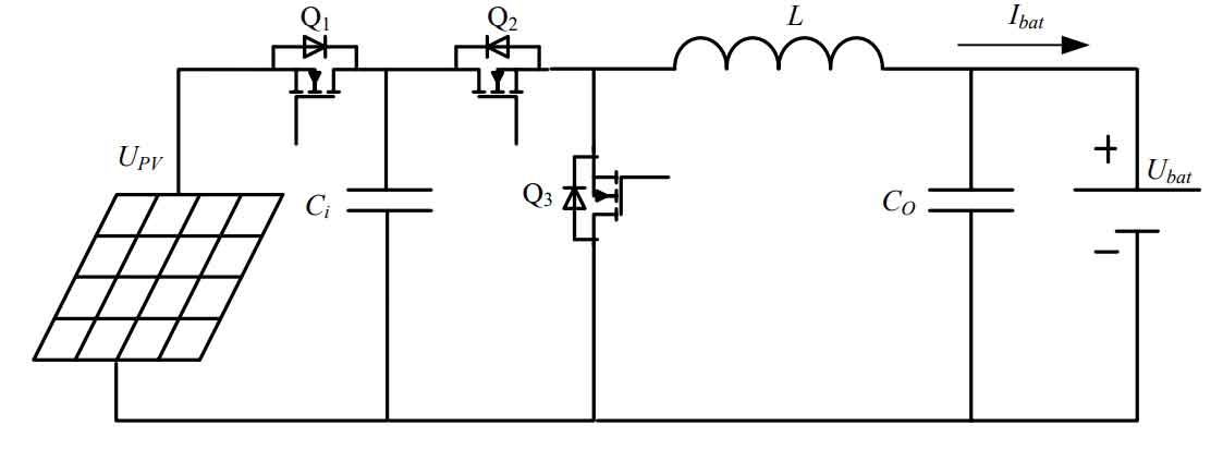
As shown in Figure 1, its working process can be summarized as follows: when Q1 and Q2 are conductive, the electrical energy of the solar panel is charged to inductor L through Q1 and Q2, and the current of inductor L shows a linear increase. Some of the stored energy will be in inductor L, while charging capacitor Co and battery. At this time, the freewheeling tube Q3 will cut off. When Q2 is turned off, the freewheeling tube Q3 conducts, and the inductor L is freewheeling and discharging, providing the previously stored energy to the capacitor Co and the battery, and the inductor current continuously decreases. The switch tube Q2 plays a role in preventing the reverse flow of battery current throughout the entire structure. At night or when solar energy is relatively weak, the electricity generated by the solar panel is very low. At this time, the voltage of the solar panel may be lower than the current voltage of the battery. If protective measures are not taken to prevent the battery from discharging the solar panel in the opposite direction, it may cause damage to the solar panel. Traditional anti backflow designs use mechanical relays to separate the solar panel from the battery. However, the output of the solar panel is unstable and unpredictable, leading to frequent switching of the relay and affecting the service life of the entire machine. This paper chooses MOSFETs instead of relays, which are not limited by the number of switching times. MOSFETs can be switched infinitely, and low-voltage MOSFETs have small internal resistance and low conduction losses.
1.2 Calculation of output inductance and capacitance of buck charging controller circuit
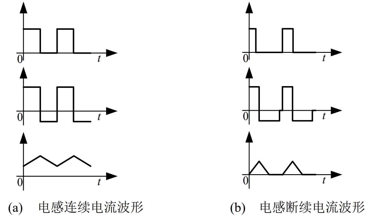
Figure 2 shows the waveform of the current flowing through the inductor in a step-down charging circuit, which can be divided into two modes: continuous mode and intermittent mode. In Figure 2 (a), the current is continuously changing in the inductance and does not exhibit a zero value, which is called the current continuous mode. In Figure 2 (b), the current undergoes discontinuous changes and a current interruption occurs, which is called the current interruption mode. Compared to the current waveform, when the current is intermittent, the inductive current in the charging circuit will be zero, causing the battery current to discharge in reverse. Therefore, synchronous rectification circuits are generally designed in current continuous mode.
The voltage reduction circuit switch uses PWM to control the output voltage, which is equivalent to a chopping circuit. In this way, the input current is not continuously input. However, when performing MPPT calculations, it is necessary to continuously sample the voltage and current of the solar panel. Generally, an electrolytic capacitor is connected in parallel at the input to filter. The relationship between PV voltage UPV and battery voltage Ubat is:
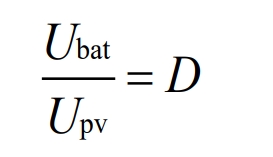
The duty cycle of the PWM wave of the main switch Q is D.
Choose to operate the inductor current in continuous current mode to calculate the inductance L value of the step-down circuit.
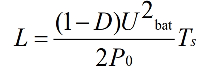
The calculated inductance value under critical conditions is 67 μ H. Based on the characteristics of solar cells, it can be concluded that based on past design experience, the ripple coefficient of the capacitor voltage at the input end of the solar panel is generally around 20%, and the filtering capacitance value can be obtained from the following equation:
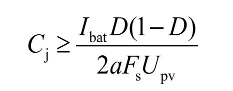
𝐼 bat is the charging current, 𝛼 is the capacitance ripple coefficient, with a value of 0.2.
Calculate Co as:
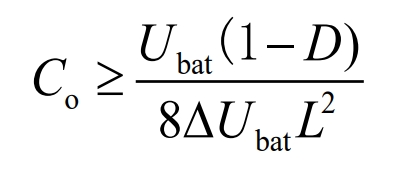
According to the formula calculation, the value of the filtering capacitor Ci at the solar panel connection end is selected as 160 V/2000 μ F. The capacitance Co of the battery charging end is 80 V/3000 μ F.
1.3 Power device calculation of charging controller
The power switch operates in high-frequency switching mode, and is driven by a PWM signal sent by a DSP that is amplified by an isolated optocoupler. It is necessary to select a power device that can adapt to high-speed switching. Based on the characteristics designed in this article, it is required to meet the requirements of high current, low loss, and low voltage power devices with a switching frequency of 50 kHz or above, while considering cost factors and choosing MOSFETs is more appropriate. The rated charging current designed in this article is 80 A, and the MOS transistor can withstand a maximum electric current Uq ≤ Upv ×α Upv ≤ 150 V, α Take 0.1 to calculate the voltage borne by the MOSFET at 165 V, and select a safe value of 200 V for the MOSFET drain to source voltage. The maximum effective value of the current passing through the MOS transistor, Igrms ≤ Ipv, peak value:
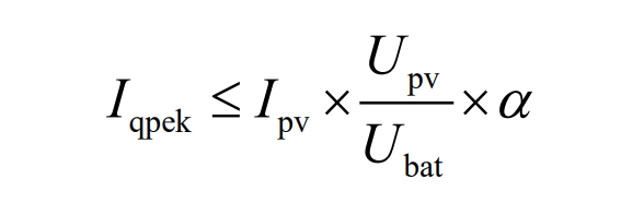
α Taking 0.1 as the calculation, Iqpek ≤ 330 A.
Based on the calculation of the power device parameters of the charger, an N-channel MOSFET with the model IRFP4668PbF produced by Infineon is selected, and its corresponding parameters are as follows:
The drain to source voltage Vdss is 200 V;
The drain to source resistance RDS (on) is 8 m Ω;
Current – continuous drain current ID is 130 A;
Each group has 3 parallel connections, requiring a total of 6 connections.
2. Analysis of charging control strategies
As shown in Figure 3, various control modes are usually proposed for the charging of lead-acid batteries. The constant current charging method refers to charging a battery according to a set constant current. The disadvantage is that the charging current is not easy to design, and excessive current can easily damage the battery. If the current is too small, the charging time is too long, and the internal resistance of the battery will change with the change of battery charge, resulting in high battery voltage. The constant voltage charging method refers to charging a battery according to a set constant voltage. Similarly, due to the change in internal resistance of the battery with the change of battery charge, there will be an initial charging stage where the internal resistance of the battery is small and the charging current is too large, causing the battery to heat up. In the later stage when the battery is approaching full charge, the internal resistance of the battery increases, and the charging current is too small, making it unable to fully charge.
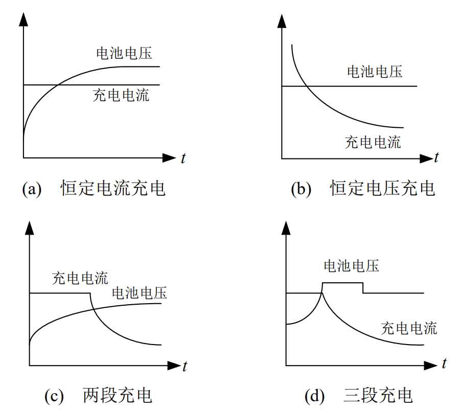
Two stage charging, the first stage charges at a fixed current value. When the battery voltage rises to the set maximum charging voltage, it enters the second stage for charging at this fixed voltage value; Three stages were optimized for two stages. When the battery voltage is stable and the charging current decreases below the set value, after a period of low current charging, the battery enters the stage of balancing its own consumption. The constant current charging method and constant voltage charging method both cause varying degrees of damage to batteries. The staged charging method combines the chemical characteristics of the battery to improve the charging process, which can extend the number of cycles of the battery. It is currently a commonly used charging method.
This article adopts a charging design that combines MPPT and three-stage charging. The charging function is activated by first implementing current limiting charging, which maximizes the rapid injection of electrical energy generated by the solar panel into the battery; The second stage is constant voltage mode, which maintains the output voltage of the charger unchanged, allowing the battery to further charge but not overcharge; After maintaining it for a period of time, enter the float charging mode, and the charging voltage switches to the float charging voltage to maintain the battery in a fully charged state.
The sun rises and the charger starts charging. At this time, the battery is in an unsaturated state. The MPPT charging method is used. As long as the charging current does not exceed the maximum current limit, the maximum electrical energy generated by the current solar panel can be injected into the energy storage battery, thereby maximizing the utilization rate of the solar energy panel. When charging reaches a certain stage, the battery voltage gradually increases to near the set maximum limit of the battery charging voltage. The charging method changes from MPPT to maintaining the output voltage of the charger unchanged. After a period of time, the charging current drops to a certain value. The controller reduces the charging voltage to the floating charging value to balance the battery’s own capacity loss and maintain a fully charged state. By combining the capacity changes of the battery and the characteristics of the solar panel’s own power generation under current meteorological conditions, the charging mode switching can be controlled to improve the MPPT efficiency of the charging controller, extend the battery’s service life, and manage the battery’s lifespan to the optimal state.
3. Summary
This article elaborates on the research and design of a household solar off grid inverter energy storage system in the solar charging and energy storage part. The solar charging and energy storage section consists of photovoltaic modules, solar power generation step-down converters, and batteries. Analyzed the working principle of a step-down non commutation converter, provided the converter design parameters and inductance current waveform, and designed a control strategy for solar charging.