
Pulse Eddy Current Thermal Imaging (PECT) technology, as a non-destructive testing method that combines pulse eddy current and infrared thermal imaging technology, has advantages such as non-contact, wide detection range, and intuitive thermal imaging results. It is suitable for detecting surface defects in parts. At present, this technology mainly focuses on thermal image processing, thermal excitation, and different material detection mechanisms, and has developed a series of detection systems. Xi’an Jiaotong University has proposed an electromagnetic thermal simulation method for effective quantitative analysis of heavy-duty gas turbines. China University of Petroleum provides a non-conductive material detection application scenario for glass fiber reinforced polymer testing. The German Institute of Non destructive Testing collaborated with Siemens to design two types of eddy current thermal imaging detection systems, fixed and portable, respectively, for crack detection of turbine blades; Its portable system consists of an induction heating power supply and a portable thermal imager. However, current research and detection systems are mostly based on commercial power sources, which have problems such as low efficiency and poor uniformity. In recent years, there has also been research on excitation power sources. Wang Xiaona et al. used a coil wound U-shaped magnetic yoke structure probe to improve the electromagnetic coupling efficiency and heating uniformity during the heating process; The team also designed a dual orthogonal excitation power supply system that can effectively improve the sensitivity of single channel excitation to crack direction and detection sensitivity. To solve the problem of resonant frequency distortion in excitation sources, the Tian GY team at the University of Newcastle in the UK proposed a fast resonant frequency tracking loop [8]. Although these studies have improved the problems of incentive sources, there are still issues such as inconvenient mobility and cumbersome operation due to the choice of direct or indirect power supply from the mains. For some special scenarios such as ships and bridges, they cannot meet the needs of on-site testing, so portable non-destructive testing equipment powered by lithium batteries has a significant application demand. At present, as a near surface crack detection method, a team has developed a portable magnetic particle detection device powered by lithium batteries; Although this device is free from the constraints of cables, its surface defect detection effect is not ideal due to its low output power. Therefore, in summary, the portable pulse eddy current thermal imaging detection system powered by lithium batteries has great application value. This article proposes a design concept for a portable power supply system, which uses lithium batteries for power supply, effectively solving the problems of cumbersome operation and inconvenient movement in pulse eddy current thermal imaging detection systems; At the same time, its excitation power supply adopts a “lithium battery+supercapacitor” structure, effectively reducing the volume and mass of the high-power excitation power supply, greatly meeting the application requirements of pulse and eddy current thermal imaging technology in on-site testing.
1. Topology and System Composition of Portable System Power Supply
The conventional pulse eddy current thermal imaging system includes a pulse induction heating power supply, an upper computer for control and thermal image data processing, a thermal imager, and experimental samples. The induction heating power supply generates a rapidly changing magnetic field above the sample through an inductive coil, and the sample is induced to produce Joule heat by inducing eddy currents. When there are defects on the surface of the sample, the heat flow is hindered; Heat accumulates near the crack, resulting in a significant temperature difference between the crack endpoint and the adjacent non crack area, known as the “tip effect”. At the same time, a thermal imager is used to record the information of the surface temperature of the sample changing with time and space; Then, the algorithm identifies abnormal temperature points and intuitively reflects crack information, thereby completing crack identification. As a key component of the pulse excitation power supply, its performance plays a decisive role in the system’s detection ability.
The PECT system requires a large pulse power output during operation, and is only powered by lithium batteries. The configured battery pack has a large mass and volume, which can affect portability. As a new type of energy storage component, supercapacitors are often used in high-power pulse excitation scenarios. By utilizing the high-power discharge characteristics of supercapacitors, the power supply volume can be reduced and the quality can be reduced. So, for the battery pack used in PECT, a combination of lithium batteries and supercapacitors was used to construct it.
At present, the combination of lithium batteries and supercapacitors mainly adopts parallel or series connection. Due to the characteristics of short time and high power output of pulse excitation sources, a series structure is adopted. Reference introduces a “dual DC/DC boost” series structure, as shown in Figure 1 (a). Based on Figure 1 (a), this article constructs a “single DC/DC boost” topology structure as shown in Figure 1 (b).
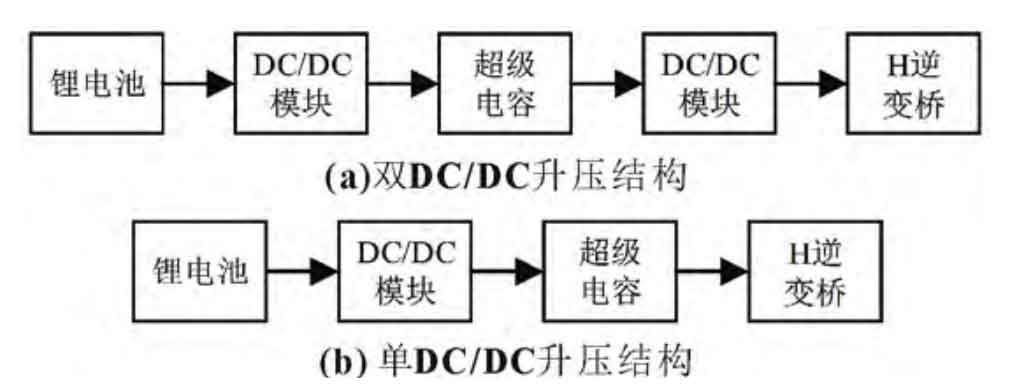
As shown in Figure 1, in the (a) structure, the lithium battery is charged to the supercapacitor by the first stage DC/DC module, and the supercapacitor is released by the H-bridge after being boosted by the second stage DC/DC module. In this structure, the working voltage selection of lithium batteries, supercapacitors, and H-inverter bridges is flexible, and supercapacitors can all choose low working voltage points (low volume mass), improving system safety. The system can also set appropriate output voltage according to needs. In the (b) structure, the lithium battery is boosted by a DC/DC module to charge a supercapacitor, which directly discharges and outputs to the H-bridge. In this structure, the working voltage of the supercapacitor is completely determined by the output demand and cannot be changed arbitrarily. To ensure high-power output, high voltage operating points are generally selected, while increasing the design requirements for the DC/DC module. However, compared with (a) structure, (b) structure reduces the number of constituent units and increases the energy utilization efficiency of the system. At the same time, the additional second stage DC/DC module in the structure (a) limits the high-power discharge capability of the supercapacitor.
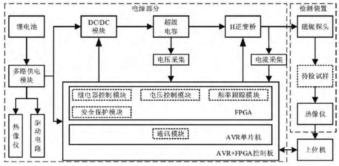
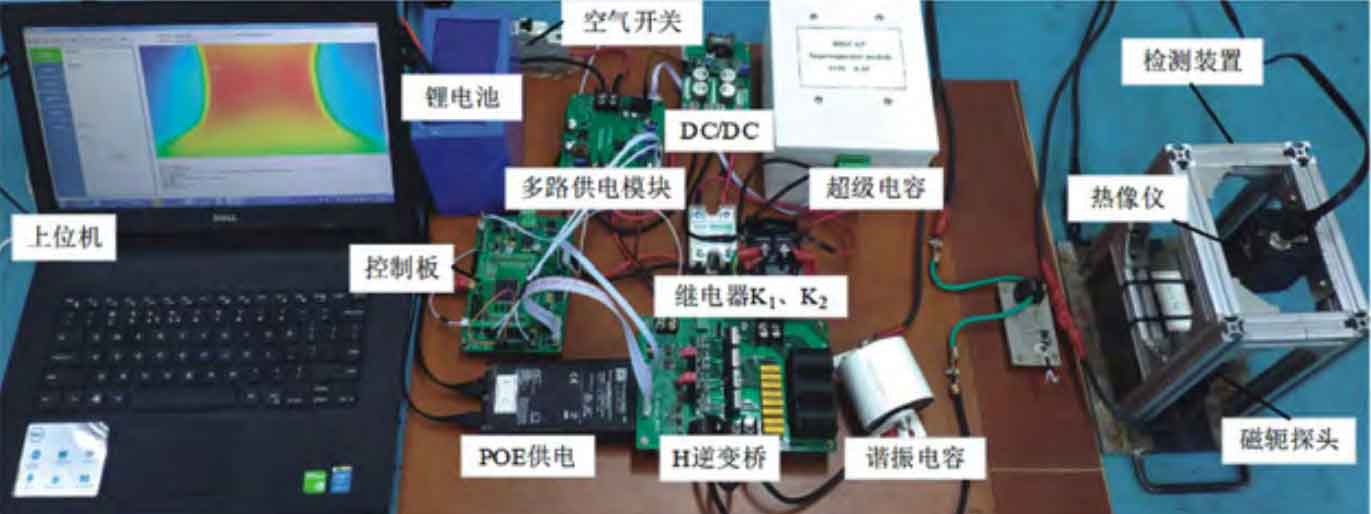
To improve energy utilization efficiency and power output capability, a portable detection system as shown in Figure 2 was designed using the “single DC/DC boost” structure shown in Figure 1 (b).
The portable detection system consists of three components: the power supply part, the upper computer, and the detection device. In the power supply section, lithium batteries are responsible for supplying system energy; The multi-channel power supply module provides different voltages for the thermal imager, control unit, voltage and current acquisition, and driving unit, etc; The DC/DC module, supercapacitor, H-inverter bridge and other components form a series structure, which releases energy through a magnetic yoke probe. The control board consists of FPGA and AVR. The FPGA unit includes a voltage control module, a frequency tracking module, a relay control module, and a safety protection module; Control the DC/DC operating mode, the on/off process of the two MOS circuits of the H inverter bridge, and the protection mechanism to monitor the voltage status of the supercapacitor and respond to system abnormalities. The AVR microcontroller completes the communication function with the upper computer and FPGA control unit. The detection device consists of a magnetic yoke probe wrapped around an inductor coil, a thermal imager, and a detection sample, all of which ensure a certain positional relationship. The upper computer is used to control the start and stop of the power supply, as well as to save and process the thermal map information of the thermal imager. When the excitation starts, the upper computer sends a signal to start the excitation, and the thermal imager starts synchronously with the excitation power supply. During the excitation process, the H inverter bridge generates an alternating voltage signal. At this point, the surface of the sample is heated, and the thermal imager collects the temperature changes on its surface. After the excitation is completed, the system automatically performs a power restoration operation on the supercapacitor, while the upper computer displays the heat map processing result, and the system waits for the next excitation operation.
2. System excitation power supply design
The power supply part, as an important unit of the detection system, is mainly excited by lithium batteries, Buck boost DC/DC, supercapacitors, H-inverter bridges, relays, and equivalent RLC circuits. The simplified power supply circuit is shown in Figure 3.
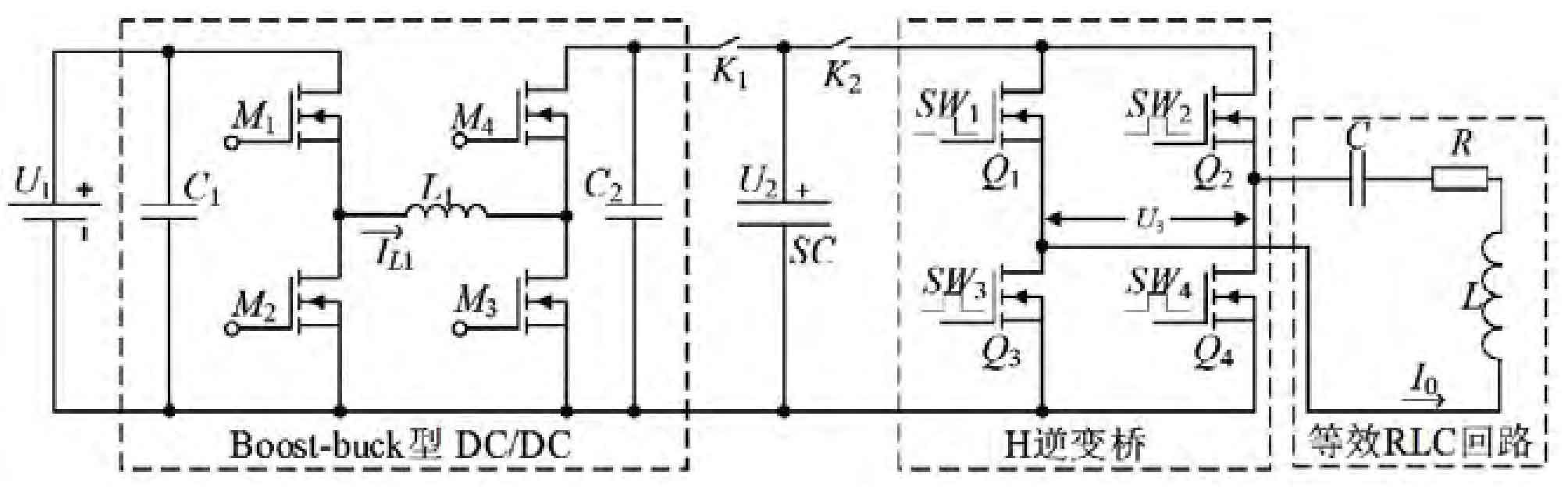
In Figure 3, U1 is a lithium battery; C1, M1, M2, M3, M4, L1, C2 form a Boost buck type DC/DC module; SC is a supercapacitor, and U2 is its voltage value; The power MOS transistors Q1, Q2, Q3, and Q4 form an H inverter bridge. SW1, SW2, SW3, and SW4 correspond to the control signals of the four MOS transistors, and U3 is their output voltage; The equivalent RLC circuit consists of an equivalent resistance R, an inductor coil L located on the magnetic yoke, and a resonant capacitor C; The equivalent resistance R is determined by factors such as loop resistance, geometric parameters of the inductor coil, and heating material, and is generally obtained through experiments; K1 and K2 are relays; I0 and IL1 represent the equivalent RLC circuit current and L1 current in the DC/DC module, respectively. To ensure the safe and stable operation of the excitation power supply, FPGA serves as the main control unit of the excitation power supply, and its control strategy is shown in Figure 4.
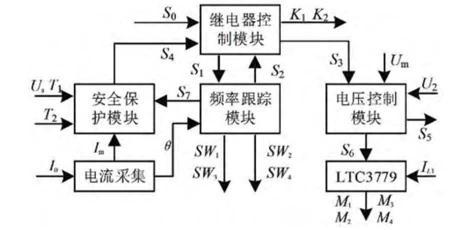
In Figure 4, Us and T1 respectively represent the individual overvoltage signal and module overheating signal of the supercapacitor; θ、 Im represents the phase and amplitude information of I0, and T2 represents the over temperature signal of the H inverter bridge; Um is the working voltage threshold set for the supercapacitor, and adjusting its value can change the excitation power of the system. LTC3779 is a voltage boosting DC/DC power chip that mainly meets the charging needs of supercapacitors from zero voltage to working voltage. M1, M2, M3, and M4 correspond to the four switch control signals of the DC/DC module. S0 is the start excitation signal of the power supply, S1 is the PWM output state signal, S2 is the end excitation signal, S3 is the start charging signal of the supercapacitor, S4 is the system protection signal, S5 is the end charging signal, S6 represents the enable signal of the DC/DC module, and S7 is the capacitive state signal (voltage lag current) of the RLC circuit during the heating process. In the actual working process, the power supply has 5 working states, and their state transitions are shown in Figure 5.
When the power system is working normally (S4=0), when it receives the power start signal S0, it enters the “wait 1” state; At this point, turn on relay K2. After a certain delay, S1 becomes effective and enters the “heating” state; At this point, start the frequency tracking module and output four PWM signals: SW1, SW2, SW3, and SW4. Real time collect the circuit current I0 and adjust the output frequency of the PWM wave to maintain the RLC circuit in a “weak inductive” state (with a small angle of voltage leading current). After the set heating time is reached, S2 becomes effective and enters the “Waiting 2” state; At this point, turn on relay K1. After a certain delay, S3 becomes effective and enters the “charging” state, at which point S6 becomes effective; The LTC3779 controller is turned on, and the supercapacitor begins to charge. When S5 is valid (U2 ≥ Um), the charging ends and enters the “initial” state; At this point, wait for the next heating to start (S0 effective), and the system will complete a normal charging and discharging process. When protection signals such as Us, T1, Im, T2, and S7 are detected during normal operation, S4 is effective and the system enters a “protection” state, turning off all output signals; After the system returns to normal, S4 is set to 0, and the system enters the “initial” state, waiting for the next heating process.
3. System prototype testing and experimentation
To verify the practicality of the portable power supply system design, a portable detection system prototype experimental platform was built as shown in Figure 6; Test its quality, volume, output power, endurance time, and crack detection effect.
In the prototype experimental platform, 24 V and 20 Ah modules were selected for the lithium battery, and 100 V and 6.5 F modules were selected for the supercapacitor. The parameters of each module of the detection system are shown in Table 1.
3.1 Output power verification
Sample 45 # was selected as the test object for the experiment, and in the equivalent RLC circuit, L is approximately 36.3 μ H. C is 0.44 μ F. The equivalent impedance R is about 3.3 Ω; The resonant frequency is approximately 39.8kHz. Set the heating time to 0.3 s and change the voltage threshold of the supercapacitor. The voltage probe and current probe (common source RP1005C) were used to measure the voltage U2 of the supercapacitor, the voltage U3 of the RLC circuit, and the current I0 during the working process. The results are shown in Figure 7.
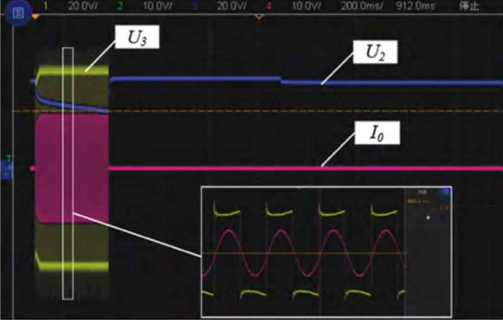
In Figure 7, the voltage of the RLC circuit is 50 V, and the effective current value is about 15 A, which means the excitation power is 0.75 kW. During the heating process (I0 ≠ 0), it can be seen that the voltage and current are stable and the phase angle can be ensured to be within a certain angle range; After heating stops (I0=0), the voltage of U2 rises and stops charging when it reaches the predetermined voltage. Due to the internal resistance of the supercapacitor, the measured voltage of U2 decreases slightly. The horizontal time base of the oscilloscope is 0.2 s/grid, which means the charging time of the supercapacitor is 0.7 s, and the system working cycle is 1 s. When the voltage threshold is set to 80 V, the heating time is still 0.3 seconds, the measured effective current is 24 A, and the capacitor charging time is 2 seconds. That is, under the excitation power of 1.92 kW, the system working cycle is 2.3 seconds. In summary, the maximum output power of the system is 1.9 kW; Under the condition of heating time of 0.3 s, the system return time is 0.7-2 s; Can meet the needs of sustained motivation in practice.
3.2 Verification of battery life
The battery life of a portable detection system is an important parameter in actual testing. Set the output power to 1.9 kW, excitation time to 0.3 s, and system cycle time to 2.3 s; As the only source of energy for the system, lithium batteries are tested for their open circuit voltage to assess the system’s endurance. After 100 repeated excitations and a period of standing, the open circuit voltage of the lithium battery before and after the experiment was measured to be 29.4 V and 29.1 V, respectively; The lithium battery has a capacity of 20 Ah and a voltage range of 24.5-29.4 V. According to the open circuit voltage method, the SOC value of a lithium battery is approximately linearly related to its open circuit voltage value [16]. It can be inferred that after 100 repeated excitations, the battery capacity of the lithium battery decreases by about 6%. Therefore, it can be inferred that in the actual process, the detection system can work 1666 times repeatedly under the conditions of excitation power of 1.9 kW and excitation time of 300 ms. At this time, the system has a power back time of 2.3 seconds, which means that under maximum power output, the continuous working time of the system is about 1.1 hours.
3.3 Crack detection effect
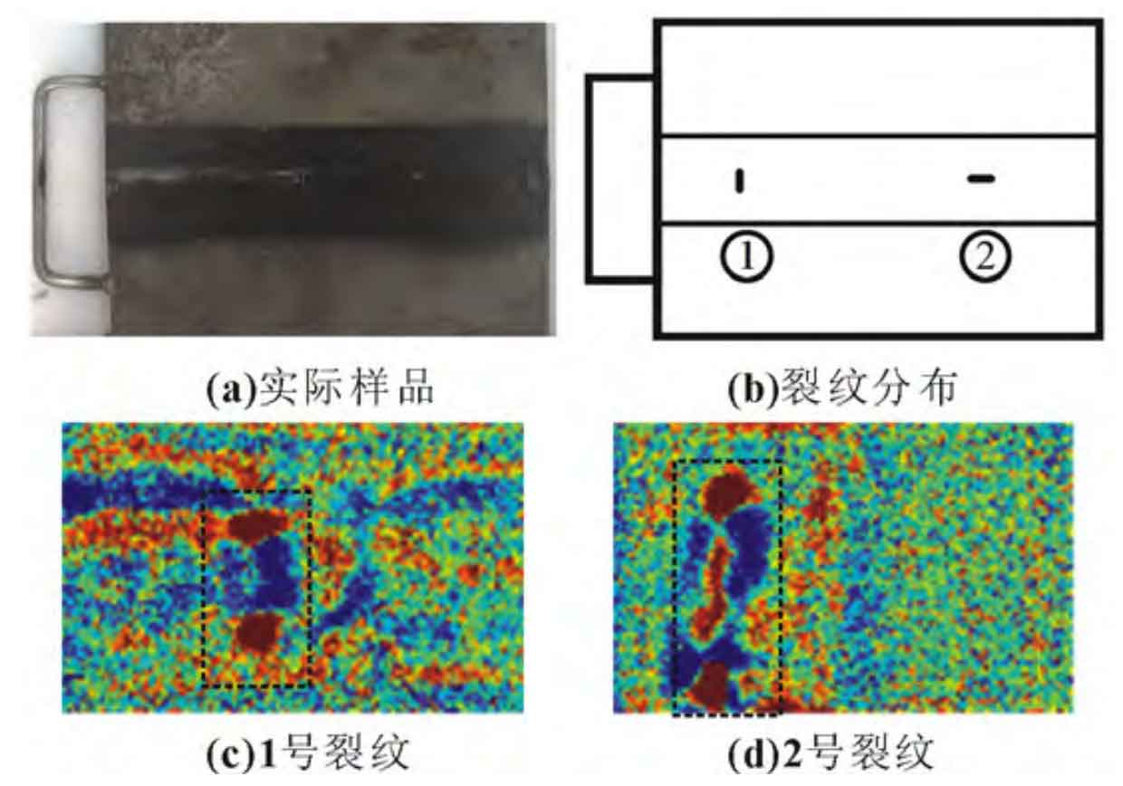
To verify the excitation effect of the power supply system, actual crack detection experiments were conducted using FLIR A35 and 45 # weld crack standard samples using thermal imagers. As shown in Figure 8, (a) is an actual weld sample, whose surface has been painted; Figure (b) shows the distribution of cracks in both vertical (No.1) and horizontal (No.2) directions, with the horizontal direction representing the overall shape of the weld seam. The experimental setup has an excitation power of 1.7 kW, a resonance frequency of 39.8 kHz, and a heating time of 0.3 seconds. The experimental data was extracted using an adaptive anomaly extraction algorithm, and the processed detection results are shown in Figures 8 (c) and (d). The black boxes marked in Figures 8 (c) and (d) correspond to crack 1 and crack 2, respectively; Due to the presence of uneven “wrinkles” in the weld seam, which are mainly distributed in the horizontal direction of the specimen, strip like heat accumulation can be seen near the crack. The test results indicate that cracks can be clearly detected under a power of 1.7 kW, indicating that the power supply system design can better meet the power requirements of pulse eddy current thermal imaging technology.
4.Conclusion
In response to the demand for on-site detection of pulsed eddy current thermal imaging technology, this paper designs a portable pulsed eddy current thermal imaging detection system based on a “single DC/DC boost” structure. The article provides a system excitation power control strategy and verifies its performance parameters and crack detection effect through a prototype experimental platform. The results show that the portable detection system prototype has a net weight of 8.4 kg, an output power of 1.9 kW, and a continuous working time of 1.1 hours. The design and testing capabilities of the power supply system have been significantly improved, which can better meet the application needs of on-site testing and provide certain application reference value.