
With the development and utilization of new energy, microgrid power supply systems are widely used in industrial parks, remote areas, border checkpoints, and other occasions. In order to keep the energy storage battery in a better working state, it is necessary to use the Energy Storage Battery Management System (BMS) to monitor and manage its status, thereby improving the efficiency of energy storage usage and achieving safe and stable operation. In microgrid energy storage, the energy storage battery cannot be fully charged and discharged, and the system requires high energy utilization and high power supply reliability standards. Therefore, the BMS of electric vehicles cannot be applied to microgrid energy storage. At present, there are still shortcomings in the application of energy storage BMS. Firstly, the estimation accuracy of the state of charge (SOC) of energy storage batteries is not high enough, which reduces the utilization rate of energy storage; The second is the energy management method based on passive equilibrium, which leads to energy waste and low equilibrium efficiency.
Therefore, this article designs an energy storage battery management system based on active balancing, adopting a master-slave system architecture and a modular design approach to achieve efficient management and energy utilization of microgrid energy storage batteries.
1. Overall scheme design
The main functions of the energy storage battery management system include data collection, SOC estimation, balance management, safety management, communication, etc. The microgrid BMS monitors the status parameters of energy storage batteries in real-time online, uses the main control module to estimate the SOC of the energy storage batteries in real-time, comprehensively analyzes and processes faults such as overvoltage, overcurrent, overheating, and energy imbalance that occur in the energy storage batteries. At the same time, it is interconnected with the microgrid energy management system (EMS), power conversion system (PCS), and upper computer, providing a basis for the scheduling and management of energy storage devices in the microgrid system. The overall design of the system is shown in Figure 1.

Its working principle is as follows: the slave control module monitors and collects real-time parameters such as voltage, temperature, and current of the energy storage battery pack. The data is filtered and processed through A/D analog-to-digital conversion, and uploaded to the main control module microprocessor (DSP) through SPI communication. The main control module obtains the corresponding sampling data for energy storage battery parameter identification and SOC estimation based on unscented Kalman filter (UKF); Analyze and judge the operating status of the energy storage battery pack. If the energy storage battery pack has overcharge, over discharge, over temperature, etc., the DSP processor will actively issue protection commands and send alarm messages; When there is inconsistency between energy storage batteries, the main control module initiates a balancing strategy and algorithm, and uses a PWM wave generator to control the balancing module to achieve consistency balancing. In addition, the main control module uploads the various status parameters of the energy storage battery to the monitoring industrial computer, EMS, PCS, etc. through CAN bus communication, providing an important basis for the management of the microgrid system.
2. System hardware design
The hardware system is the foundation for stable operation of BMS. The working principle of this article is as follows: the slave control module monitors and collects real-time parameters such as voltage, temperature, and current of the energy storage battery pack. The data is filtered and processed through A/D analog-to-digital conversion, and uploaded to the main control module microprocessor (DSP) through SPI communication. The main control module obtains the corresponding sampling data for energy storage battery parameter identification and SOC estimation based on unscented Kalman filter (UKF); Analyze and judge the operating status of the energy storage battery pack. If the energy storage battery pack has overcharge, over discharge, over temperature, etc., the DSP processor will actively issue protection commands and send alarm messages; When there is inconsistency between energy storage batteries, the main control module initiates a balancing strategy and algorithm, and uses a PWM wave generator to control the balancing module to achieve consistency balancing. In addition, the main control module uploads the various status parameters of the energy storage battery to the monitoring industrial computer, EMS, PCS, etc. through CAN bus communication, providing an important basis for the management of the microgrid system.
3. System hardware design
The hardware system is the foundation for stable operation of BMS. The hardware of the energy storage battery management system designed in this article mainly includes the main control module, data acquisition module, balance module, power module, communication module, etc.
3.1 Selection of main control module chips
The main control module chip is the brain of BMS, responsible for tasks such as data reception, computation, and management instruction issuance. It has a large amount of computation and complex logical control. This article selects the TMS320F2812 chip, which operates at a frequency of 150 MHz and has an instruction cycle of approximately 6.67 ns. It comes with 128 kB of FLASH memory space and 18 kB of RAM, as well as external memory, 16 12 bit ADC conversion channels, and various communication interface modules such as SCI, SPI, and CAN. It can better adapt to the complex environment of microgrid energy storage systems and meet the requirements of energy storage battery management system controllers. Design the main control chip minimization system according to the chip user manual, including reset circuit, crystal oscillator circuit, filtering circuit, etc., to form the core control part of the energy storage battery management system.
3.2 Voltage acquisition and equalization circuit
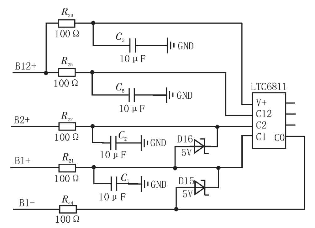
The voltage reflects the working status of energy storage batteries and provides important data support for SOC estimation and safety management of energy storage batteries. This article uses the LTC6811 chip to complete the tasks of voltage monitoring and active balancing management for energy storage batteries. The chip has high voltage acquisition accuracy and strong anti-interference performance, and can measure up to 12 series energy storage battery cell voltages with a measurement range of 0-5 V. Its built-in analog-to-digital converter facilitates the transmission of measurement results without the need for additional ADC modules. Through the SPI communication interface, communication with the main control module can be achieved. Multiple LTC6811 chips can use daisy chain form to achieve more energy storage battery detection. The digital chip Si8441 is selected for isolation, and only the underlying chip needs to be connected to the main control module through the isoSPI port.
The voltage measurement circuit of the LTC6811 chip is shown in Figure 2. Measure the voltage of 12 batteries using the chip voltage acquisition terminal, and introduce an RC filter circuit on the measurement branch, with a resistance of 100 Ω and a capacitance of 10 μ F. It can achieve effects such as improving high-frequency noise interference and reducing voltage ripple; A voltage regulator is connected in parallel between the positive and negative electrodes of the energy storage battery, with a value greater than twice the working voltage of the battery, thereby improving the chip’s surge resistance.
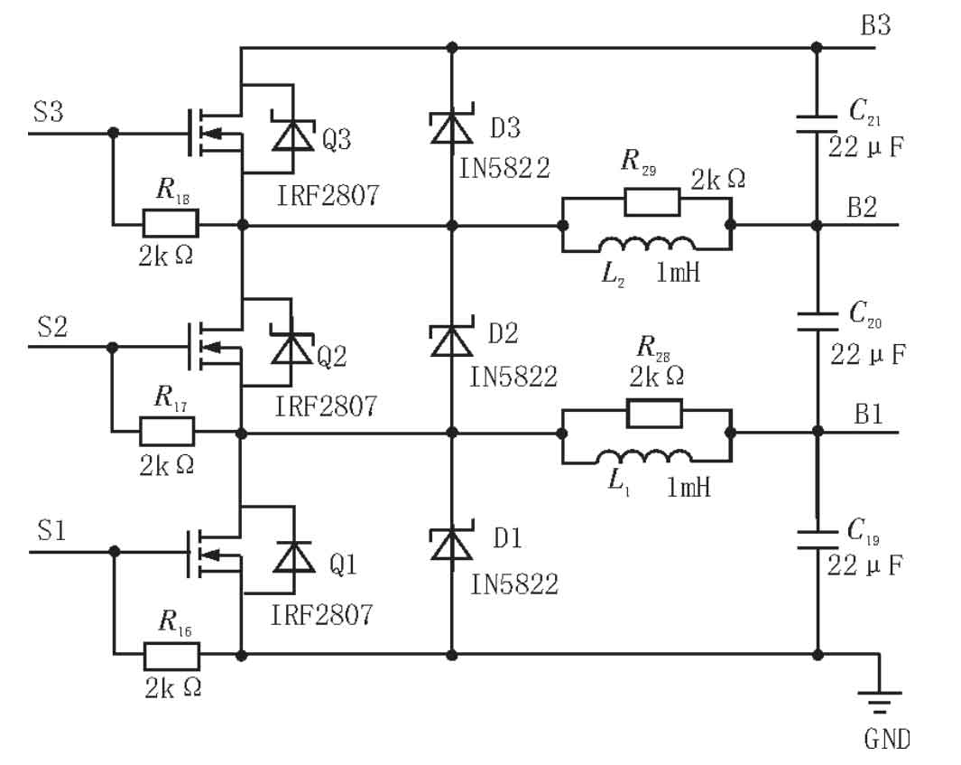
This article relies on the LTC6811 chip and designs an improved Buck Boost active equalization circuit to achieve consistency management of energy storage batteries, as shown in Figure 3. Utilizing the interface of the chip to achieve control of the balanced circuit switch transistor, using IRF2807 N-channel MOSFET, the maximum current can reach 20 A, the maximum VDS can reach 75 V, the conduction time is short, and the impedance is small; The diode is selected as the IN5822 Schottky diode, which has a small forward conduction voltage drop and can improve the equalization efficiency; Parallel connection of a 1 k Ω resistor between the source gates of MOSFETs can prevent gate voltage overshoot and improve circuit EMC performance; Considering that the wiring from LTC6811 to the energy storage battery is relatively long, and the high-frequency current passes through the wire during equalization, causing energy loss, a parallel connection of 22 is made at the positive and negative electrode interfaces of the energy storage battery μ F ceramic capacitor, thereby improving balanced energy efficiency.
3.3 Current and temperature acquisition circuit
The ADC module and General Purpose I/O (GPIO) interface integrated inside the LTC6811 chip provide a convenient way for current and temperature measurement, which can convert external sensor measurements into voltage sampling systems. Using DS18B20 single line digital temperature sensor, compared to thermistors, its temperature measurement accuracy is higher and convenient to use. The temperature sensor can be connected in parallel through a data bus for data communication, achieving multi-point temperature collection. The circuit design is shown in Figure 4. The VCC pin of the temperature sensor DS18B20 is connected to a+3.3 V power supply, the GND pin is grounded, and the signal pin wire DQ is connected in parallel to an I/O port of LTC6811, and connected to the high level through a pull-up resistor.

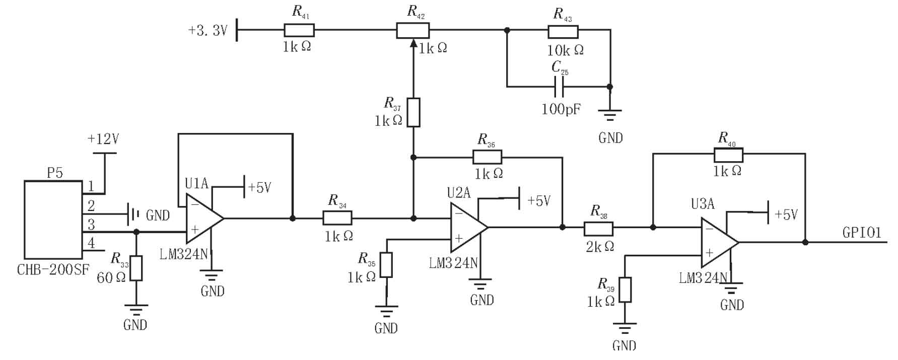
The Hall current sensor has high sensitivity and accuracy in detecting current, and the CHB-200SF Hall current sensor with closed-loop compensation is selected. The current collection circuit is shown in Figure 5. The Hall current sensor detects the primary current and obtains the secondary current through magnetic induction effect. The detected current signal is first converted into a voltage signal through resistor R16, and then processed by noise reduction, reverse, and adder. Finally, the signal that meets the conditions is input to the I/O interface of LTC6811, and an internal ADC conversion module is used to achieve synchronization of voltage and current data acquisition and conversion.
3.4 Power module
The chips and components used in the main control module and acquisition module both require different voltage supplies in order to operate normally and efficiently. Therefore, different DC/DC power modules are required for voltage conversion. In the design, each module is powered by an energy storage battery pack, without the need for additional power supply. The power supply voltage levels required in the circuit mainly include 12, 5, 3.3 V, etc.
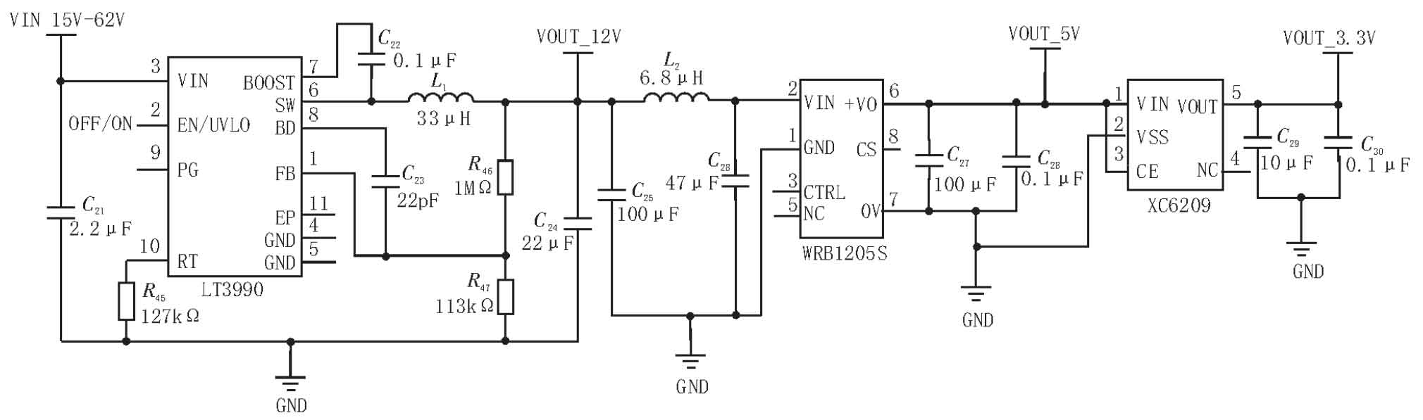
By using the LT3990 regulated power supply chip to obtain power from the 12 series batteries monitored by the voltage measurement chip, a voltage of 15-62 V can be converted to 12 V. Then, the isolated step-down power supply chip WRB1205S is used to convert the 12 V voltage to 5 V. Finally, the XC6209 chip is used to convert the 5 V voltage to 3.3 V. The circuit diagram is shown in Figure 6.
4. System software design
Develop software for the minimization system of the main control module TMS320F2812 in the Code Warrior development environment to achieve the core control functions of the energy storage battery management system. The main programs include hardware system initialization, data collection, SOC estimation, active balancing management, security protection, communication configuration, etc.
The system first performs initialization settings, initializes and assigns configuration parameters such as clock, I/O port, and communication. Then, runs the parameter collection subroutine to sample voltage, current, and temperature. The results are converted by the ADC module and uploaded to the DSP through SPI serial communication. The SOC estimation subroutine and safety protection subroutine based on the unscented Kalman filtering algorithm run synchronously to detect the working status of the energy storage battery and ensure the safe operation of the system; The active equalization subroutine with SOC as the equilibrium variable obtains the SOC of the energy storage battery and determines whether the equalization needs to be turned on, thereby achieving consistency management of the series energy storage battery. Finally, information and control instructions are exchanged with peripheral devices such as the upper computer, EMS, PCS, etc. through CAN bus communication.
5. Experimental verification
Using 12 batteries connected in series to form a battery pack, as the experimental object of the energy storage battery management system, the main verification is to verify measurement accuracy, balance effect, and other contents.
5.1 Detection accuracy testing
The detection of energy storage battery status is the foundation for the normal operation of the energy storage battery management system, and its detection accuracy directly affects the effectiveness of BMS management. Test the voltage of series energy storage batteries using a Fluke175C digital multimeter and compare it with the voltage detection results of the energy storage battery management system. The results are shown in Table 1. The Fluke175C digital multimeter has a DC voltage measurement resolution of 0.1 mV and extremely high measurement accuracy, which can be used as the actual experimental value. From the data in Table 1, it can be seen that the difference between the BMS sampling values and the measured values on the multimeter is within ± 5 mV, indicating a high measurement accuracy of the voltage of the single energy storage battery and meeting the design requirements.
| Battery SN | Sampling value/V | Measured value/V | Error/mV |
| 1 | 3.245 | 3.249 | 4 |
| 2 | 3.252 | 3.254 | 2 |
| 3 | 3.201 | 3.200 | -1 |
| 4 | 3.250 | 3.247 | -3 |
| 5 | 3.184 | 3.186 | 2 |
| 6 | 3.215 | 3.218 | 3 |
| 7 | 3.226 | 3.223 | -3 |
| 8 | 3.237 | 3.241 | 4 |
| 9 | 3.268 | 3.266 | -2 |
| 10 | 3.216 | 3.218 | 2 |
| 11 | 3.221 | 3.218 | -3 |
| 12 | 3.239 | 3.244 | 5 |
Verify the accuracy of system temperature collection using a constant temperature box. Place the battery pack in a constant temperature oven, set the temperature range of the oven to -10~+50 ℃, and conduct an experiment every 10 ℃. The temperature sampling results are shown in Table 2. From the table, it can be seen that the temperature sampling error of the system is within ± 1 ℃, indicating a high measurement accuracy.
| Thermostat temperature/℃ | System sampling temperature/℃ | Error/℃ |
| -10 | -10.5 | -0.5 |
| 0 | -0.2 | -0.2 |
| 10 | 9.7 | -0.3 |
| 20 | 20.1 | 0.1 |
| 30 | 29.8 | -0.2 |
| 40 | 40.6 | 0.6 |
| 50 | 50.8 | 0.8 |
5.2 Equilibrium experiment testing
Two sets of series energy storage batteries were tested, and the initial SOC of each set of energy storage batteries was the same. The difference in maximum SOC of each individual energy storage battery in the group was 6%. The first set of energy storage batteries was connected to the equalization circuit, while the second set was not connected to the equalization system. Perform constant current discharge on the entire energy storage battery pack through an electronic load, and record the SOC data displayed on the upper computer every 3 minutes. The test time is 30 minutes, and the results are shown in Table 3. The SOC error of the final single energy storage battery of the energy storage battery pack using a balanced system is within 1%, while the maximum SOC error of the single energy storage battery of the unbalanced energy storage battery pack reaches 6.09%, indicating a trend of increasing inconsistency.
| Battery SN | Initial SOC (%) | First group equilibrium SOC (%) | Second group unbalanced SOC (%) |
| 1 | 74 | 68.85 | 70.52 |
| 2 | 76 | 68.92 | 71.23 |
| 3 | 73 | 68.57 | 68.85 |
| 4 | 75 | 68.75 | 70.21 |
| 5 | 72 | 68.34 | 67.95 |
| 6 | 70 | 68.05 | 65.14 |
6. Conclusion
A master-slave architecture was adopted to design an energy storage battery management system for the microgrid energy storage system. Based on TMS320F2812 and LTC6811 chips, modular circuit design was used to complete functions such as energy storage battery pack status detection, SOC estimation, balance management, and safety protection. This can achieve efficient management of series energy storage battery packs. Through physical verification of the system, the voltage measurement accuracy of this design is within 5 mV, and the temperature measurement accuracy is 1 ℃, indicating high detection accuracy; The active balancing management based on SOC ensures that the consistency of energy storage battery packs is controlled within 1%, which has a good balancing effect and provides good reference value for practical applications.