
With the popularization and application of intelligent technology, the urban Internet of Things has made urban management more efficient and convenient. The Internet of Things outdoor lighting system effectively achieves online monitoring of solar street lights, making the application of Internet of Things street lights increasingly widespread. The solar control system based on the Internet of Things has broken the traditional way that street light control systems can only perform simple switch control and cannot achieve positioning, control, and real-time monitoring of individual lights. It will become increasingly important for the application fields of the Internet of Things, including energy utilization.
1. Overall System Design
The IoT solar street light control system based on long-distance wireless communication (hereinafter referred to as the “IoT street light control system”) consists of a solar street light terminal, a data collector, and a cloud server. The terminal communicates with the concentrator through the LoRa module, while the concentrator communicates with the server through the 4G module. Its main functions are as follows.
1) The terminal device mainly collects and reads the operating parameters of solar street lights, and transmits the processed data to the corresponding concentrator through the LoRa module.
2) The concentrator is responsible for forwarding the instructions issued by the server to the terminal device, or transmitting the data transmitted by the terminal device to the control system backend through wireless communication protocol.
3) The server first verifies the concentrator number and terminal device number, analyzes the received data after verification, and monitors the urban outdoor lighting system through the computer (PC) browser user interface (UI).
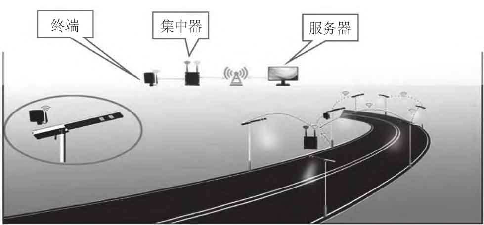
The communication network diagram of the Internet of Things street light control system is shown in Figure 1.
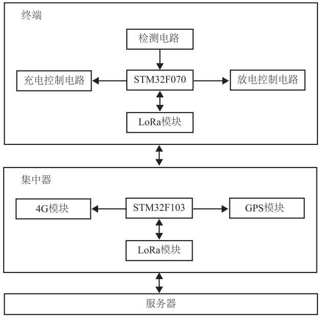
As shown in Figure 2, the terminal device of the Internet of Things street light control system consists of the main control chip STM32F070, charging control circuit, discharging control circuit, detection circuit, and LoRa module. The main control chip performs charging and discharging control as well as data detection, and the LoRa module uploads the data detected by the main control chip to the server through a concentrator. The concentrator of the Internet of Things street light control system consists of the main control chip STM32F103, 4G module, GPS module, and LoRa module. Its working process is as follows: the LoRa module of the concentrator obtains data transmitted from the terminal device, which is processed by the main control chip STM32F103, and then wirelessly communicated by the 4G module and sent to the server, The user sends control instructions through the UI, which are transmitted to the concentrator through wireless communication protocol. After being processed by the main control chip STM32F103, the LoRa module of the concentrator forwards the data to the terminal device, realizing the user’s monitoring of street lights.
2 Hardware Design
2.1 Selection of main control chip and power module
The main control chip of the terminal device is selected from STM32F0 series microcontroller of STF Semiconductor Company. The input voltage is battery voltage, with a range of 2.83.65V. The working voltage of the main circuit in the terminal device is 12V, and the working voltage of the LoRa module is 5V. In the concentrator, the voltage of the 4G module is 3.7V, and the voltage of the main control chip STM32F103 and GPS is 3.3V.
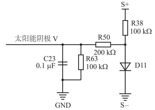
2.2 Detection circuit
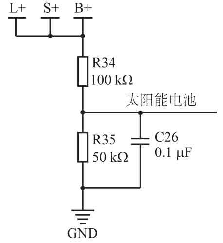
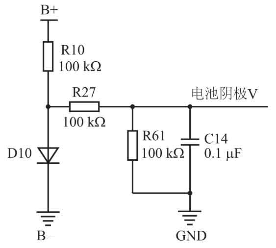
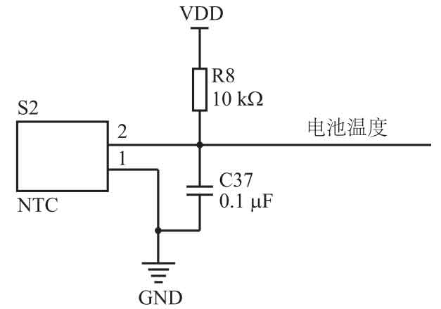
The detection circuit of the terminal device is shown in Figure 3. The system adopts a common positive design, which connects the battery positive electrode, solar positive electrode, and load positive electrode. The solar voltage, battery voltage, and load voltage are all collected through resistance voltage division. The voltage after resistance voltage division is collected by the analog-to-digital converter of the main control chip, and the voltage value is calculated. The battery cathode, solar cathode, and circuit GND are connected using D10 and D11 diodes, Detect the voltage between the solar anode (S+) and the solar cathode (S -), as well as the voltage between the battery anode (B+) and the battery cathode (B -), and calculate the solar voltage and battery voltage. This design meets the requirement of being powered by solar energy when the battery voltage is too low. To ensure that the battery operates in a safe temperature environment, NTC thermistors are used to detect the temperature of the battery.
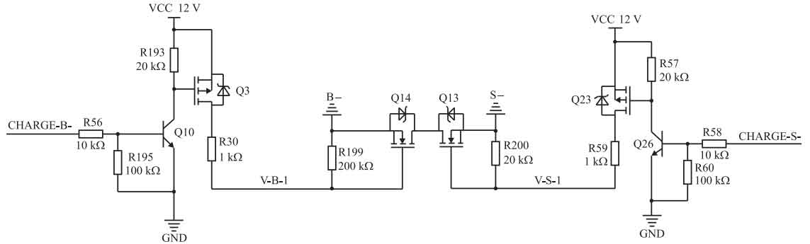
2.3 Charging control circuit
The charging control circuit of the terminal device is shown in Figure 4. This circuit controls charging by controlling the conduction and turn off of field-effect transistors Q14 and Q13. At the CHARGE-B end, the PWM output from the main control chip controls the conductivity of Q14, thereby controlling the magnitude of the charging current; At the CHARGE-S end, the high and low level signals output by the main control chip control the conduction and closure of Q13, thereby achieving charging control.
2.4 Discharge control circuit
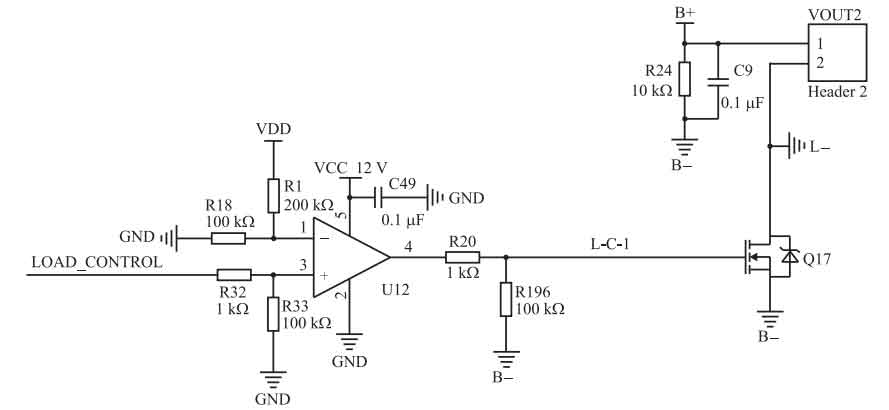
The terminal discharge control circuit is shown in Figure 5. This circuit controls discharge by controlling the conduction and turn off of the field-effect transistor Q17. The load control terminal is connected to the PWM signal output by the main controller, and the signal at the load control terminal is compared with the circuit GND through U12 to control the conduction and shutdown of Q17. VOUT2 is the light interface.
2.5 Selection of communication modules
The terminal device and concentrator both use LoRa module circuits, and their typical usage is shown in Figure 6. The LoRa module uses E32 ⁃ 900T20S_U, which has the characteristics of long communication distance, strong anti-interference ability, and high confidentiality.
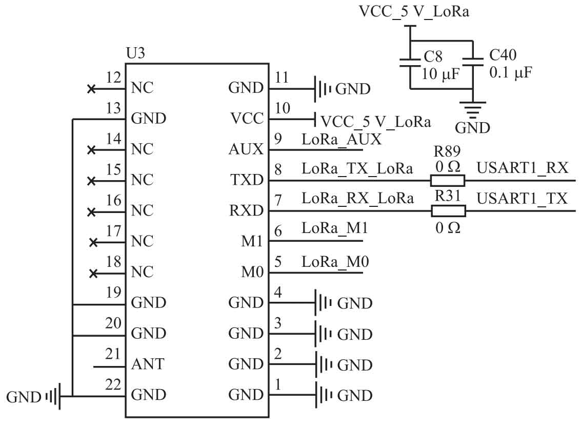
The GPS module in the concentrator uses the Air530Z module, which supports multiple satellite navigation systems and achieves joint positioning of multiple systems. The 4G module in the concentrator uses the LTECat4 wireless communication module launched by Mobile Communications.
3. Software Design
The menu bar interface of the Internet of Things street light control system platform includes menu items such as “Data Monitoring”, “Map Positioning”, “Terminal Control”, “Project Management”, “Historical Reports”, etc.
1) Under “Data Monitoring”, there are functions such as “Data Statistics”, “Charging and Discharging Data Statistics”, and “Global Distribution of Terminal Numbers”, which can perform data statistics on the number of projects, concentrators, and terminals. It can also perform data statistics on the charging/discharging volume for the past 7 days, the past month, and the past year, as well as the global distribution of terminal numbers.
2) The “map positioning” function can locate and search for any terminal for user management and maintenance.
3) There are “Parameter Configuration”, “Parameter Summary”, and “Alarm Summary” function items under “Terminal Control”. “Parameter configuration” can refresh, remotely control, obtain real-time parameters, and set parameters for terminals. It can query and update information for all terminals, and set the working mode of terminals according to different environments; “Parameter summary” can display the working status and data information of all terminals; The alarm summary displays the status and data information of the problematic terminal.
4) Users can add and delete backend projects and concentrators through Project Management; Enter the ID based on the concentrator number, and each street lamp needs to be entered based on its terminal number.
5) Users can view the historical charging and discharging data of each street lamp through the “Historical Report” for operation and maintenance purposes.
4. Implementation of IoT Street Light Control Systems
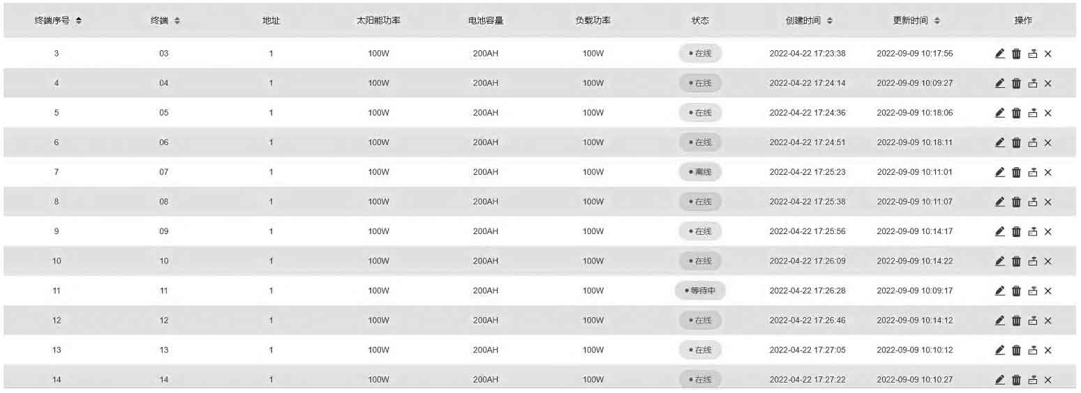
Test the Internet of Things street light control system, including wireless signal, data analysis, and overall performance of the Internet of Things platform. Under remote monitoring, the Internet of Things street light control system can monitor the real-time operation of each terminal and implement remote control. Figure 7 shows the online status of 12 terminals monitored by the system platform during the testing process. It can be seen that terminal 7 is offline and terminal 11 is waiting to connect. Table 1 lists the operational status of 12 terminals under remote detection. It can be seen that both Terminal 13 and Terminal 14 are in low battery mode with a real-time capacity of 10%, Terminal 7 is offline, and Terminal 11 is waiting for connection. If the offline or waiting connection status exceeds the set threshold days, it is necessary to investigate the cause of the offline or waiting connection status and troubleshoot.
The test results show that the Internet of Things street light control system can meet the nighttime road lighting needs; Capable of real-time transmission of terminal working status for upper computer display, and real-time monitoring of the operation status of solar street lights; Being able to locate each street lamp for maintenance personnel to repair damaged ones; Ability to view historical data through the system, allowing users to view the required past data.
| Terminal number | Charging state | Load status | Load power/W | Real time power/W | Real time capacity/% |
| 03 | Non charging | Second time | 100 | 80 | 60 |
| 04 | Non charging | Second time | 100 | 100 | 80 |
| 05 | Non charging | Second time | 100 | 100 | 80 |
| 06 | Non charging | Second time | 100 | 100 | 80 |
| 07 | Non charging | off-line | 100 | 0 | 0 |
| 08 | Non charging | Second time | 100 | 60 | 100 |
| 09 | Non charging | Second time | 100 | 60 | 100 |
| 10 | Non charging | Second time | 100 | 80 | 80 |
| 11 | Non charging | Waiting | 100 | 0 | 0 |
| 12 | Non charging | Second time | 100 | 100 | 80 |
| 13 | Non charging | Low Power MODE | 100 | 100 | 10 |
| 14 | Non charging | Low Power MODE | 100 | 100 | 10 |
5. Conclusion
This article designs an IoT solar street light control system based on LoRa communication, which can achieve remote data transmission, online monitoring, remote control and other functions, and can obtain real-time operation status of solar street lights. Compared to traditional street lights, this system has more advantages, such as being suitable for different environments, saving a lot of manual maintenance costs, and being able to perform timely maintenance to reduce equipment scrap rates. The successful design and application of this system will create conditions for building a solar street light control system for the Internet of Things and creating smart cities and smart villages.