
In recent years, the increasing environmental pollution and depletion of traditional energy resources have highlighted the urgent need for sustainable alternatives. As a researcher focused on renewable energy solutions, I have designed an automatic switching system that integrates an off-grid solar system with grid power to ensure reliable and efficient energy supply. This system leverages solar photovoltaic (PV) technology to reduce carbon emissions and promote energy independence, while the automatic switching mechanism maintains uninterrupted power for critical loads. The core innovation lies in using battery voltage as the switching criterion, enabling seamless transitions between solar and grid power based on predefined thresholds. Throughout this article, I will elaborate on the design principles, configuration, control strategies, and experimental validation of this off-grid solar system, emphasizing its practicality and effectiveness. The term ‘off-grid solar system’ will be frequently referenced to underscore its centrality in this work.
The design principles of the automatic switching system are rooted in maximizing energy efficiency and ensuring load continuity. As the primary designer, I prioritized the use of an off-grid solar system to harness solar energy without feeding excess power back into the grid, thereby avoiding grid instability issues commonly associated with grid-tied systems. The system operates on a DC 48V baseline, with switching decisions based on the voltage of the energy storage system. Specifically, when the battery voltage exceeds 48V, the off-grid solar system powers the load, and surplus energy charges the batteries. Conversely, when the voltage drops below 44V, grid power takes over, simultaneously charging the batteries. This approach not only optimizes solar energy utilization but also serves as a backup during grid outages, ensuring that devices like electric vehicle charging stations operate without interruption. The design emphasizes robustness, scalability, and minimal environmental impact, aligning with global sustainability goals.
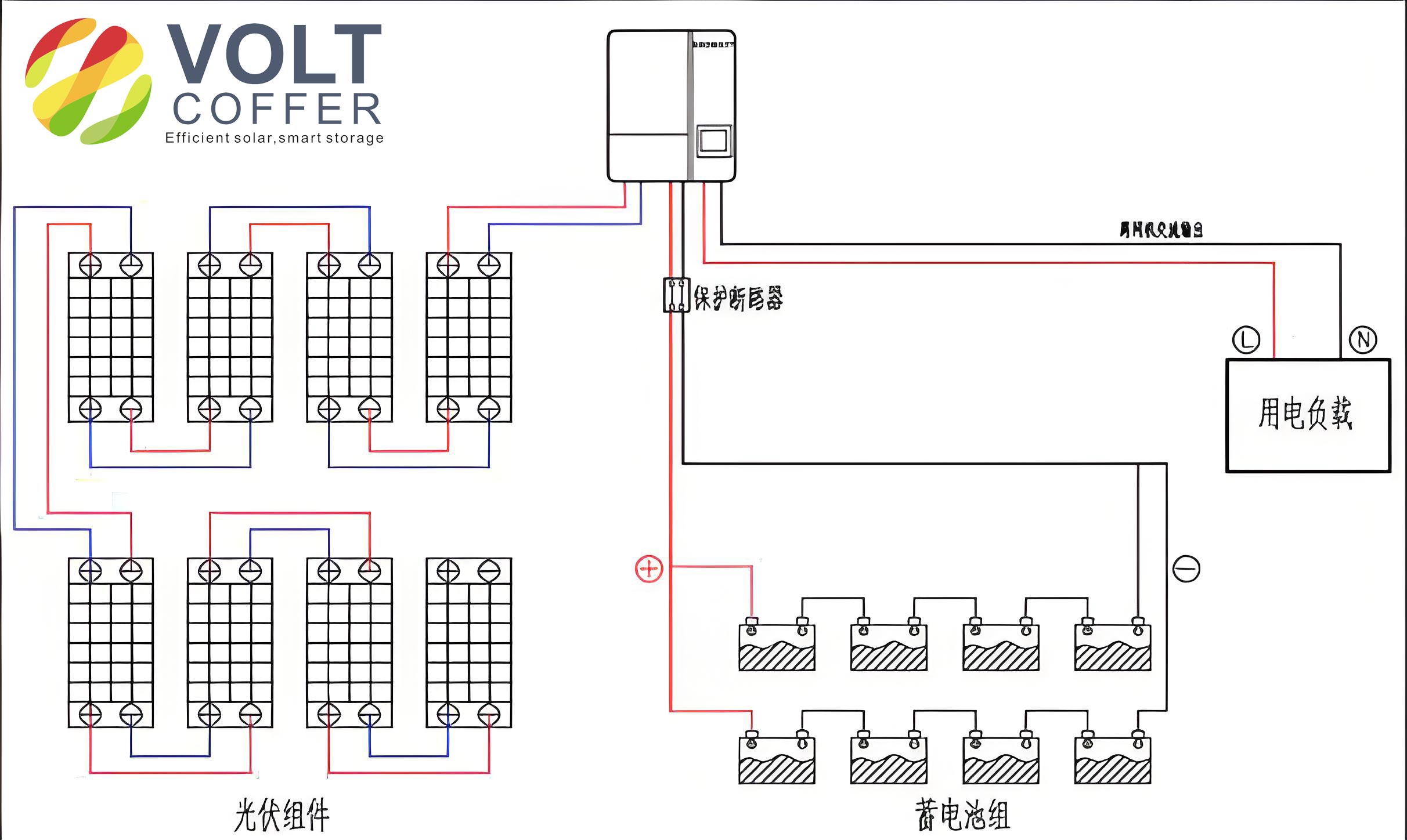
To achieve these objectives, I configured the off-grid solar system with several key components, each selected for compatibility and performance. The system includes a PV array, a solar charge controller, a battery storage unit, a sine wave inverter, a voltage controller, a computer for monitoring, and an AC charging station representing the load. The PV array consists of six 250W monocrystalline silicon panels arranged in a series-parallel configuration to achieve a total capacity suitable for the system’s demands. The charge controller, rated for 48V systems with a maximum input power of 3.2kW, ensures maximum power point tracking (MPPT) to optimize solar energy harvest. Energy storage is provided by eight 120Ah lead-acid batteries, forming a 48V bank, while the sine wave inverter converts DC to 220V AC for the load. The voltage controller, integrated with an STM32 microcontroller, monitors battery voltage and triggers switching actions. For clarity, Table 1 summarizes the key components and their specifications.
| Component | Specification | Role in System |
|---|---|---|
| PV Array | 6 x 250W panels, 2 series 3 parallel | Generates DC power from sunlight |
| Charge Controller | 48V, 3.2kW max input, MPPT | Regulates battery charging and PV input |
| Battery Storage | 8 x 120Ah lead-acid, 48V total | Stores energy for later use |
| Sine Wave Inverter | 5kW, 48V DC input, 220V AC output | Converts DC to AC for loads |
| Voltage Controller | STM32-based, voltage sensing | Monitors battery voltage and controls switching |
| AC Charging Station | Simulated load for testing | Represents real-world application |
The automatic switching system design centers on a control circuit that uses real-time battery voltage measurements to dictate power sources. I employed an STM32 microcontroller as the core processing unit, coupled with a BJHVS-AS5-05 voltage sensor that detects voltages from -1V to 150V. The sensor outputs an analog voltage signal proportional to the measured battery voltage, and the relationship is defined by the formula: $$ V_{in} = \frac{A_{out} – A_{out\_0V}}{0.0125} $$ where \( A_{out} \) is the output voltage of the sensor, and \( A_{out\_0V} \) is the static voltage when no input is applied. This formula allows for accurate voltage monitoring, which is critical for reliable switching. The controller is programmed with setpoints for start and stop voltages—48V and 44V, respectively—ensuring that the off-grid solar system activates when sufficient solar energy is available and deactivates when backup grid power is needed. The logic can be expressed using a conditional statement: if \( V_{battery} \geq 48V \), then use solar power; else if \( V_{battery} \leq 44V \), switch to grid power. This simple yet effective control strategy minimizes energy waste and enhances system longevity.
To further illustrate the control parameters, I have derived mathematical models for energy flow and efficiency. The power generated by the PV array can be calculated using: $$ P_{pv} = \eta_{pv} \times A \times G $$ where \( P_{pv} \) is the PV power output, \( \eta_{pv} \) is the efficiency of the panels, \( A \) is the area, and \( G \) is the solar irradiance. For the battery system, the state of charge (SOC) relates to voltage through a nonlinear function, approximated as: $$ SOC = \frac{V_{battery} – V_{min}}{V_{max} – V_{min}} \times 100\% $$ where \( V_{min} \) and \( V_{max} \) are the minimum and maximum allowable voltages. These equations help in optimizing the off-grid solar system for various conditions. Additionally, the inverter efficiency \( \eta_{inv} \) affects the AC output power: $$ P_{ac} = \eta_{inv} \times P_{dc} $$ where \( P_{dc} \) is the DC input power. Table 2 provides a summary of key parameters used in the system design.
| Parameter | Symbol | Value | Description |
|---|---|---|---|
| Battery Voltage High Threshold | \( V_{high} \) | 48V | Voltage to switch to solar power |
| Battery Voltage Low Threshold | \( V_{low} \) | 44V | Voltage to switch to grid power |
| PV Array Power | \( P_{pv} \) | 387W (experimental) | Rated power under test conditions |
| Inverter Efficiency | \( \eta_{inv} \) | ~90% | Approximate conversion efficiency |
| Load Power | \( P_{load} \) | 800W | Simulated load for testing |
For experimental validation, I conducted tests using a simulated load to replicate real-world scenarios, such as electric vehicle charging. The off-grid solar system was set up with all components connected: the PV array to the charge controller, the battery bank to the inverter, and the inverter to an AC load—specifically, a 800W electric kettle used as a substitute for a charging station. This kettle heated 1.8L of water from 8°C to 100°C, mimicking the energy demand of an EV charger. During the 13-minute test, I monitored parameters like PV power, AC voltage, frequency, and battery voltage to assess system performance. The data collected demonstrated the stability of the off-grid solar system under varying conditions. For instance, the AC voltage remained around 220V with minor fluctuations, and the battery voltage stayed constant at approximately 53.1V, indicating effective energy management. The PV power output was steady at 387W, which, though lower than the load demand, was supplemented by the batteries to maintain uninterrupted operation.
The results from the experiment were analyzed to evaluate the system’s reliability and efficiency. As shown in Table 3, the key metrics during the test highlight the off-grid solar system’s ability to provide consistent power. The AC voltage averaged 220V with a standard deviation of less than 2V, confirming the inverter’s stability. The frequency of the AC output remained near 49.83Hz, with slight variations that did not impact performance. Importantly, the battery voltage did not drop below the threshold, ensuring that the solar system remained active throughout the test. This demonstrates the practicality of the automatic switching mechanism in maintaining load continuity without manual intervention. The success of this experiment underscores the potential of off-grid solar systems in applications like remote power supply or emergency backup, where grid reliability is a concern.
| Parameter | Average Value | Range | Comments |
|---|---|---|---|
| AC Voltage | 220V | 218-222V | Stable within acceptable limits |
| PV Power Output | 387W | Constant | No significant variation |
| AC Frequency | 49.83Hz | 49.80-49.85Hz | Minor fluctuations, negligible |
| Battery Voltage | 53.1V | 53.0-53.2V | Above switching threshold |
| Heating Time | 13 minutes | N/A | Water heated from 8°C to 100°C |
In conclusion, the design and implementation of this automatic switching system for an off-grid solar system have proven successful in achieving seamless power source transitions based on battery voltage. I have detailed the components, control logic, and experimental validation, all of which confirm the system’s ability to provide reliable AC power for loads like electric vehicle chargers. The use of an STM32 microcontroller and voltage sensors ensured precise control, while the off-grid solar system demonstrated efficiency in harnessing renewable energy. This approach not only reduces reliance on fossil fuels but also enhances energy security in off-grid or unstable grid environments. Future work could focus on optimizing the system for higher power applications or integrating smart grid features for broader adoption. Overall, this project highlights the viability of off-grid solar systems as a sustainable solution for modern energy challenges.