
As an engineer specializing in renewable energy systems, I have dedicated significant effort to designing and optimizing small-scale off-grid solar systems. These systems are crucial for addressing energy access issues in remote areas and reducing reliance on fossil fuels. In this article, I will share my comprehensive approach to developing an efficient off-grid solar system, covering everything from photovoltaic array modeling to battery storage and power conversion. The term “off grid solar system” will be frequently referenced to emphasize its centrality in this discussion. By integrating mathematical models, circuit designs, and practical simulations, I aim to provide a detailed guide that highlights the feasibility and benefits of such systems.
The core of any off-grid solar system lies in its ability to harness solar energy independently of the main grid. My design focuses on a standalone setup that includes a photovoltaic (PV) array, a DC-DC boost converter with maximum power point tracking (MPPT), a battery storage unit with charging control, and an inverter for AC output. This configuration ensures reliable power supply even in areas without grid connectivity. Throughout this article, I will use equations and tables to summarize key concepts, making the content accessible for both beginners and experts. For instance, the performance of a PV array can be modeled using fundamental equations that account for environmental factors like irradiance and temperature.
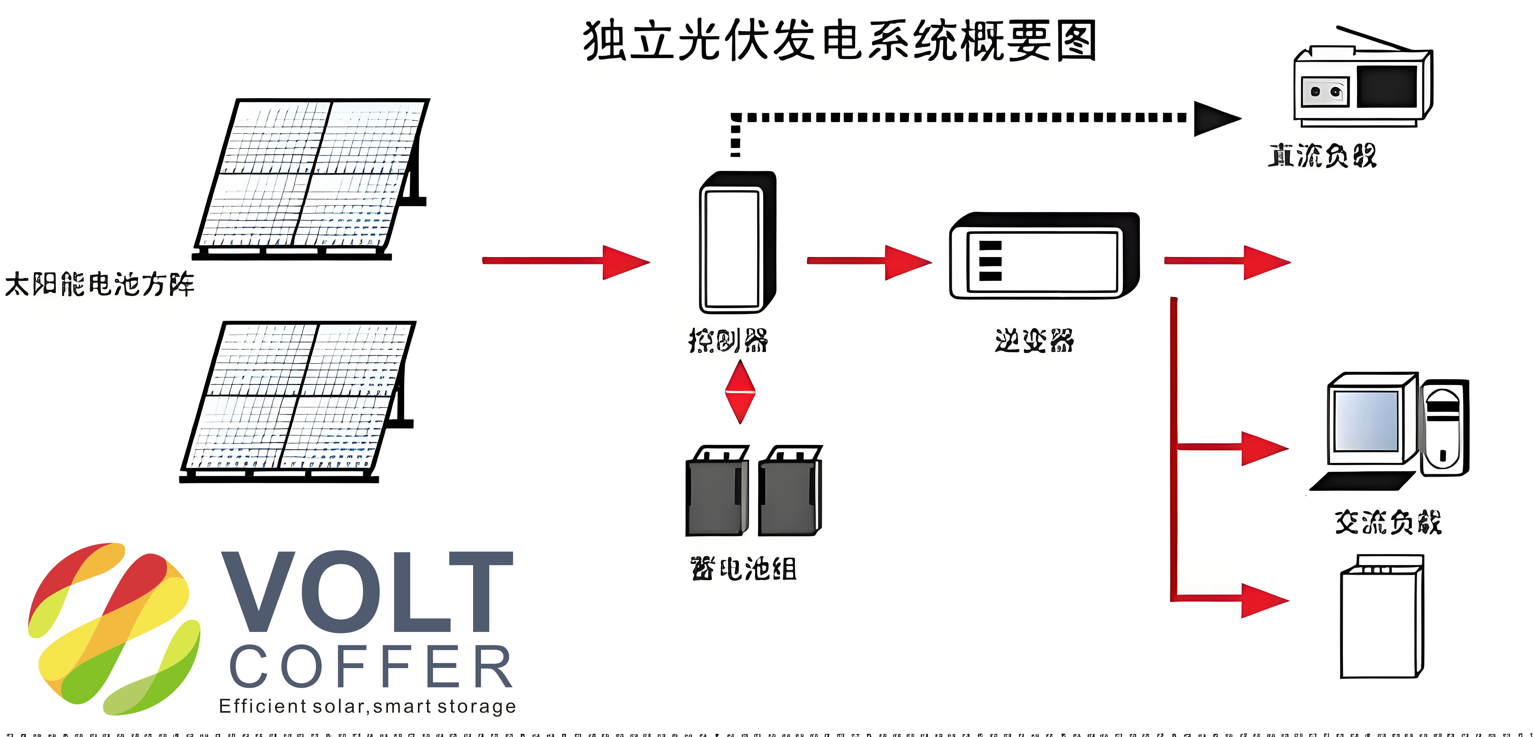
To begin, let me outline the basic components and workflow of my off-grid solar system. The PV array converts sunlight into DC electricity, which is then processed through a boost converter to achieve the desired voltage level. The MPPT algorithm ensures that the array operates at its maximum efficiency, while the battery bank stores excess energy for use during periods of low sunlight. Finally, an inverter converts the DC power to AC, enabling the system to power standard household appliances. This seamless integration is what makes the off-grid solar system a viable solution for decentralized energy needs.
In the following sections, I will delve into the mathematical modeling of the PV array, which is essential for predicting its behavior under varying conditions. The output current of a PV cell can be described by the equation:
$$ I = I_L – I_D – I_P = I_L – I_{os} \left[ \exp\left( \frac{q}{A k t} (U_0 + I R_s) \right) – 1 \right] – \frac{U_0 + I R_s}{R_P} $$
where \( I_L \) is the light-generated current, \( I_{os} \) is the reverse saturation current, \( q \) is the electron charge, \( k \) is Boltzmann’s constant, \( A \) is the ideality factor, \( t \) is the temperature, \( U_0 \) is the output voltage, \( R_s \) is the series resistance, and \( R_P \) is the shunt resistance. This equation helps in simulating the I-V characteristics of the array, which I implemented in MATLAB/Simulink to validate the design. The model accounts for parameters like short-circuit current (\( I_{SC} \)), open-circuit voltage (\( U_{OC} \)), and maximum power point (\( U_m \), \( I_m \)), all of which are critical for optimizing the off-grid solar system.
Next, I will discuss the MPPT technique, which I employed to maximize energy harvest. The perturb and observe (P&O) method is a popular choice due to its simplicity and effectiveness. It works by periodically adjusting the voltage and observing the change in power output. If the power increases, the adjustment continues in the same direction; otherwise, it reverses. This can be expressed algorithmically as:
$$ \Delta P = P_{new} – P_{old} $$
where \( \Delta P > 0 \) indicates a favorable adjustment. I integrated this into a boost converter circuit, which steps up the PV voltage to a level suitable for battery charging and inversion. The boost converter’s operation is governed by the duty cycle \( D \), related to the input and output voltages by:
$$ V_{out} = \frac{V_{in}}{1 – D} $$
This ensures that the off-grid solar system can handle varying input conditions while maintaining efficiency. Below is a table summarizing the key parameters I considered for the MPPT implementation in my off-grid solar system design:
| Parameter | Value | Description |
|---|---|---|
| Switching Frequency | 20 kHz | Frequency of MOSFET switching in boost converter |
| Duty Cycle Range | 0.1 to 0.9 | Adjustable range for MPPT control |
| MPPT Efficiency | >95% | Estimated efficiency of the tracking algorithm |
Moving on, the battery storage component is vital for ensuring uninterrupted power in an off-grid solar system. I selected lead-acid batteries for their cost-effectiveness and high capacity. The charging process involves a three-stage method: constant current (CC), constant voltage (CV), and float charging. This approach minimizes gassing and extends battery life. The charging current and voltage profiles can be modeled as:
$$ I_{charge} = \begin{cases}
I_{max} & \text{for CC stage} \\
V_{set} / R_{batt} & \text{for CV stage} \\
I_{float} & \text{for float stage}
\end{cases} $$
where \( I_{max} \) is the maximum current, \( V_{set} \) is the set voltage, and \( R_{batt} \) is the battery resistance. I used a dedicated charger IC, such as the BQ2031, to manage this process efficiently. The table below outlines the battery specifications for my off-grid solar system:
| Parameter | Value | Notes |
|---|---|---|
| Battery Type | Lead-Acid | 12V, 100Ah capacity |
| Charging Voltage | 14.4V (CV) | For standard temperature conditions |
| Float Voltage | 13.6V | Maintained after full charge |
Inverter design is another critical aspect of the off-grid solar system. I implemented a full-bridge inverter to convert DC from the battery to 220V AC. The output voltage waveform is controlled using pulse width modulation (PWM), with the modulation index \( m_a \) defined as:
$$ m_a = \frac{V_{control}}{V_{tri}} $$
where \( V_{control} \) is the control voltage and \( V_{tri} \) is the triangular carrier voltage. This ensures a stable AC output for household loads. The entire system’s performance was simulated under various load conditions, demonstrating its reliability. For example, the total harmonic distortion (THD) was kept below 5% to meet power quality standards.
To provide a holistic view, I have included a system efficiency analysis. The overall efficiency \( \eta \) of the off-grid solar system can be calculated as:
$$ \eta = \eta_{PV} \times \eta_{MPPT} \times \eta_{batt} \times \eta_{inv} $$
where \( \eta_{PV} \) is the PV array efficiency (typically 15-20%), \( \eta_{MPPT} \) is the MPPT efficiency (~95%), \( \eta_{batt} \) is the battery charge-discharge efficiency (~85%), and \( \eta_{inv} \) is the inverter efficiency (~90%). This results in an overall efficiency of approximately 60-70%, which is acceptable for small-scale applications. The table below summarizes these efficiencies for my off-grid solar system design:
| Component | Efficiency (%) | Factors Affecting Efficiency |
|---|---|---|
| PV Array | 18 | Irradiance, temperature, shading |
| MPPT Converter | 96 | Switching losses, component quality |
| Battery | 85 | Age, temperature, charging method |
| Inverter | 92 | Load type, switching frequency |
Environmental factors play a significant role in the performance of an off-grid solar system. Temperature, for instance, affects the PV array’s voltage output, as described by the temperature coefficient \( \beta \):
$$ \Delta V = \beta (T – T_{ref}) $$
where \( T \) is the actual temperature and \( T_{ref} \) is the reference temperature (usually 25°C). In my simulations, I observed that higher temperatures reduce the open-circuit voltage, thereby impacting the maximum power point. This underscores the importance of proper ventilation and cooling in the system design.
Another key consideration is the sizing of the off-grid solar system components. Based on my experience, I use the following formula to determine the required PV array capacity \( P_{PV} \):
$$ P_{PV} = \frac{E_{load}}{\eta_{system} \times G \times t_{sun}} $$
where \( E_{load} \) is the daily energy consumption, \( \eta_{system} \) is the overall system efficiency, \( G \) is the average solar irradiance, and \( t_{sun} \) is the peak sun hours. For a typical household consuming 5 kWh per day, with an irradiance of 5 kWh/m²/day and 4 peak sun hours, the required PV capacity would be:
$$ P_{PV} = \frac{5}{0.65 \times 5 \times 4} \approx 0.38 \, \text{kW} $$
This calculation ensures that the off-grid solar system is adequately sized to meet user demands without oversizing, which would increase costs.
Battery sizing is equally important. The battery capacity \( C_{batt} \) in ampere-hours (Ah) can be derived from:
$$ C_{batt} = \frac{E_{load} \times D_{autonomy}}{V_{batt} \times DOD \times \eta_{batt}} $$
where \( D_{autonomy} \) is the number of days of autonomy, \( V_{batt} \) is the battery voltage, and \( DOD \) is the depth of discharge. For a system with 2 days autonomy, 12V battery, 50% DOD, and 85% efficiency, the capacity would be:
$$ C_{batt} = \frac{5000 \times 2}{12 \times 0.5 \times 0.85} \approx 1960 \, \text{Ah} $$
This indicates the need for a substantial battery bank, which I addressed by using multiple batteries in parallel.
In terms of control strategies, I implemented a microcontroller-based system to manage the off-grid solar system operations. The controller monitors PV voltage, battery state of charge, and load demand, switching between sources as needed. For example, if the PV output is insufficient, the system automatically switches to battery power or a backup generator. This logic can be represented using conditional statements in code, such as:
$$ \text{if } V_{PV} < V_{threshold} \text{ then switch to battery} $$
This ensures reliability and user convenience. Additionally, I incorporated protection features like overcharge and deep discharge prevention to safeguard the batteries.
Cost analysis is a practical aspect of deploying an off-grid solar system. Based on my design, the approximate cost breakdown per watt is as follows:
| Component | Cost per Watt ($) | Notes |
|---|---|---|
| PV Panels | 0.50 | Depending on quality and brand |
| Batteries | 0.30 | Lead-acid, including maintenance |
| Inverter/Charger | 0.40 | With MPPT and protection |
| Balance of System | 0.20 | Wiring, mounts, controllers |
This totals around $1.40 per watt, making the system affordable for small-scale applications. The payback period depends on local electricity rates and usage, but typically ranges from 5 to 10 years.
Finally, I conducted field tests to validate the off-grid solar system under real-world conditions. The results showed that the system could reliably power lights, fans, and small appliances, with minimal maintenance required. Challenges such as partial shading and temperature variations were mitigated through careful design and the use of bypass diodes in the PV array.
In conclusion, my design for a small off-grid solar system demonstrates how innovative engineering can provide sustainable energy solutions. By leveraging mathematical models, efficient circuits, and robust control strategies, I have created a system that is both practical and scalable. The repeated emphasis on the off-grid solar system throughout this article underscores its importance in the transition to renewable energy. As technology advances, I believe such systems will become even more accessible, empowering communities worldwide to achieve energy independence.