
The continuous evolution of agricultural practices demands integration with advanced technologies to enhance productivity, resource efficiency, and sustainability. As a researcher deeply invested in precision agriculture, I have focused on developing systems that transcend traditional farming limitations. A primary challenge in modern horticulture, particularly in greenhouse cultivation, is maintaining an optimal microclimate while minimizing operational costs and external energy dependence. Conventional monitoring methods, reliant on manual observation and intervention, are inherently imprecise, labor-intensive, and unable to provide real-time, holistic environmental management. This inefficiency directly impacts crop yield, quality, and resource utilization.
To address these challenges, I designed and implemented a comprehensive intelligent greenhouse monitoring system. The core philosophy of this design is to create a self-sustaining, closed-loop ecosystem for plant growth. The system leverages the Internet of Things (IoT) for pervasive sensing and control, and critically, integrates a dedicated solar system as the primary energy source. This autonomous solar system is fundamental to the project’s viability, ensuring continuous operation independent of unreliable grid power, especially in remote agricultural areas. The entire infrastructure—from sensors to actuators—is powered by this renewable solar system, making the greenhouse truly sustainable.
The system’s architecture is built upon a distributed wireless sensor network (WSN) that forms the sensory nervous system of the greenhouse. Each node within this network is responsible for collecting critical ambient parameters. The aggregated data is wirelessly transmitted to a central gateway and then to an upper-computer (PC) for visualization, analysis, and historical logging. Furthermore, the system incorporates an automatic maintenance robot for physical intervention tasks. All these components are energized by the meticulously designed photovoltaic solar system, complemented by a wind turbine backup, creating a robust hybrid power solution. The following diagram illustrates the high-level topology of this integrated system.
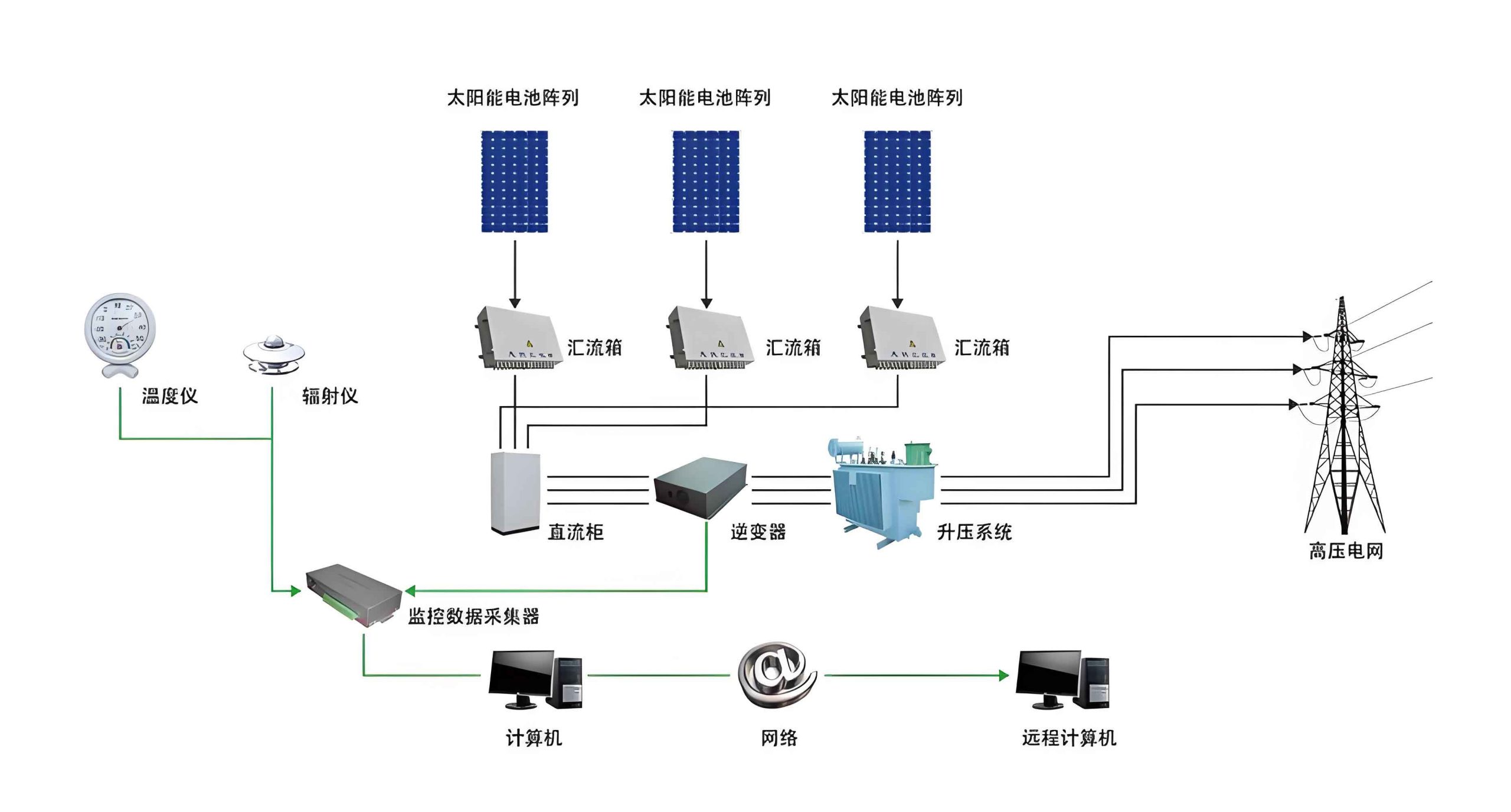
1. System Architecture and Operational Framework
The proposed system is a synergy of several technological modules working in concert. The architecture can be decomposed into four primary layers: the Power Layer, the Perception & Data Acquisition Layer, the Network & Control Layer, and the Application Layer.
1.1 Power Layer: The Autonomous Solar System
This layer is the cornerstone of the system’s sustainability. The design employs a photovoltaic (PV) array as the main generator. The energy yield from this solar system depends on several factors, which can be summarized by the fundamental photovoltaic power equation:
$$ P_{pv} = A \cdot G \cdot \eta_{pv} $$
where \( P_{pv} \) is the output power (W), \( A \) is the total area of the PV panels (m²), \( G \) is the solar irradiance (W/m²), and \( \eta_{pv} \) is the conversion efficiency of the panels. To ensure uninterrupted operation during nights or cloudy days, the solar system includes a battery bank for energy storage. A charge controller manages the charging/discharging cycles to protect the batteries. A small wind turbine acts as an auxiliary source, diversifying the renewable energy mix and enhancing the reliability of the overall power solar system. The specifications of the power layer are detailed in Table 1.
| Component | Specification / Model | Primary Function |
|---|---|---|
| PV Panel | Polycrystalline, 300W, 24V | Primary DC power generation |
| Wind Turbine | Vertical Axis, 400W, 24V | Auxiliary power generation |
| Charge Controller | MPPT, 40A, 24V/48V | Optimizes PV output, manages battery charging |
| Deep Cycle Battery | Gel, 200Ah, 12V (2 in series) | Stores energy for non-generation periods |
| System Voltage | 24V DC | Operational voltage for all components |
1.2 Perception & Data Acquisition Layer
This layer comprises the sensor nodes deployed throughout the greenhouse. Each node is an embedded system centered on a CC2430 system-on-chip (SoC), which integrates a high-performance 2.4 GHz RF transceiver and an 8051 microcontroller. The node is interfaced with a suite of sensors:
- Temperature & Humidity: SHT10 digital sensor.
- CO₂ Concentration: MG811 electrochemical sensor module.
- Soil Moisture: FC-28 resistive sensing module.
- Light Intensity: BH1750FVI digital ambient light sensor.
The CC2430 reads sensor data, performs preliminary processing (e.g., unit conversion, filtering), and prepares it for wireless transmission. The power for each node is drawn from the main 24V DC bus of the solar system via efficient DC-DC buck converters.
1.3 Network & Control Layer
The sensor nodes form a ZigBee-based mesh network (using the CC2430’s built-in protocol stack). This network offers low power consumption, robustness, and self-healing capabilities. A designated coordinator node acts as the network gateway, collecting data from all router and end-device nodes. The coordinator is connected to the upper-computer via a serial-to-USB interface. Based on the real-time data and predefined setpoints, control algorithms running on the upper-computer generate command signals. These commands are sent back through the network to actuator nodes, which control:
– Water solenoid valves for irrigation.
– Relays for Red/Blue LED grow lights.
– The drive and arm motors of the maintenance robot.
1.4 Application Layer
This is the user interface, typically a custom software application on a PC or cloud server. It displays real-time sensor readings in numerical and graphical formats, logs historical data, allows users to set environmental thresholds (setpoints), and provides manual override controls for all actuators and the robot.
2. Detailed Hardware Design and Implementation
The hardware realization involved careful circuit design and integration to ensure reliability and efficiency, fully supported by the solar system.
2.1 Wireless Sensor Node Design
The core circuit revolves around the CC2430 SoC. External components include a 32.768 kHz crystal for the sleep timer, a 32 MHz crystal for the RF core, a 2.4 GHz PCB antenna, and decoupling capacitors. Sensor interfaces use appropriate signal conditioning circuits. For instance, the analog output from the MG811 CO₂ sensor is fed into the CC2430’s ADC input through a low-pass filter to reduce noise. The SHT10 and BH1750FVI use I²C digital communication. The node’s average current consumption was optimized to be below 5mA in active sensing mode and below 1µA in deep sleep, making it perfectly suited for the battery-backed solar system.
2.2 Actuator and Control Circuitry
Actuator control is achieved through relay modules driven by the GPIO pins of auxiliary microcontroller units (like Arduino) that function as actuator nodes within the ZigBee network. The soil moisture control loop uses the FC-28 module. When the measured soil moisture value \( M_{soil} \) falls below a critical threshold \( M_{thresh} \), the control logic triggers the relay to open the solenoid valve. The irrigation continues until \( M_{soil} \geq M_{thresh} \).
For light supplementation, the BH1750FVI sensor monitors Photosynthetically Active Radiation (PAR). The control algorithm is more sophisticated, considering both intensity and photoperiod (light duration). The required daily light integral (DLI) for a crop can be expressed as:
$$ DLI_{req} = \int_{t_{sunrise}}^{t_{sunset}} PAR(t) \, dt + \int_{t_{on}}^{t_{off}} PAR_{LED}(t) \, dt $$
where \( DLI_{req} \) is the crop-specific requirement (mol/m²/d), the first integral is natural light contribution, and the second is the LED supplement. The system calculates the deficit and activates Red (660nm) and Blue (450nm) LED arrays in a specific ratio \( R:B \) for a computed duration \( t_{supp} \) to meet the \( DLI_{req} \).
2.3 Indoor Autonomous Maintenance Robot
The robot is a mobile platform equipped with:
– A microcontroller (e.g., ESP32) for local control and WiFi connectivity.
– Motor drivers and DC gear motors for movement.
– A multi-degree-of-freedom robotic arm for delicate tasks like removing diseased leaves or placing sensors.
– A WiFi camera for real-time video feed and remote visual inspection.
– An onboard battery charged from the greenhouse’s solar system via a docking station.
The robot receives high-level navigation and task commands (e.g., “go to sector B3,” “inspect plant row 5”) from the upper-computer via WiFi, executing them autonomously using odometry and sensor feedback.
3. System Software and Control Algorithms
The software was developed using the IAR Embedded Workbench for the CC2430 nodes and a higher-level language (like Python or C#) for the upper-computer application.
3.1 ZigBee Protocol Stack Configuration
The Z-Stack (Texas Instruments) was modified to define appropriate application profiles, endpoints, and clusters for our sensor data and control commands. The coordinator was configured to establish the network and manage node joining. Router nodes were placed strategically to extend network coverage.
3.2 Data Acquisition and Transmission Flow
On each sensor node, the firmware follows a periodic cycle:
1. Wake up from sleep mode.
2. Power up and read all connected sensors.
3. Packetize the data (Node ID, Sensor Readings, Battery Voltage).
4. Transmit the packet to the parent node (router or coordinator).
5. Enter deep sleep mode for a configurable interval (e.g., 5 minutes).
This duty cycling is crucial for power conservation, aligning perfectly with the energy budget provided by the solar system.
3.3 Closed-Loop Environmental Control Algorithms
The upper-computer runs proportional-integral-derivative (PID) controllers for continuous parameters like temperature. The control signal \( u(t) \) for the heating/cooling system is calculated as:
$$ u(t) = K_p e(t) + K_i \int_0^t e(\tau) \, d\tau + K_d \frac{de(t)}{dt} $$
where \( e(t) = T_{setpoint} – T_{measured}(t) \) is the error, and \( K_p \), \( K_i \), \( K_d \) are tuning gains. For discrete actions like irrigation and CO₂ enrichment (via controlled release), hysteresis-based (on/off) controllers are used to prevent actuator chattering.
The logic for the maintenance robot involves path planning and task sequencing algorithms. Upon receiving a task, it plots a collision-free path using its internal map of the greenhouse, executes the movement, and then runs the specific arm manipulation routine.
4. System Testing and Performance Evaluation
The complete system was prototyped and tested in a controlled environment simulating a 6m x 10m greenhouse section. The performance of each subsystem was rigorously validated.
4.1 Power System (Solar System) Performance
The hybrid solar system was tested under various weather conditions. Table 2 shows the energy generation and consumption balance over a 72-hour period, confirming the system’s self-sufficiency.
| Time Period | PV Generation (Wh) | Wind Generation (Wh) | Total System Load (Wh) | Battery State of Charge (End) |
|---|---|---|---|---|
| Day 1 (Sunny) | 2450 | 120 | 980 | 95% |
| Day 2 (Cloudy) | 850 | 280 | 920 | 78% |
| Day 3 (Rainy) | 180 | 450 | 900 | 65% |
4.2 Sensor Network Accuracy and Reliability
Sensor readings were compared against calibrated commercial instruments. The wireless network’s packet delivery ratio (PDR) and latency were measured. Results confirmed high accuracy and reliable communication suitable for agricultural monitoring.
| Parameter | Sensor Used | Measured Range | Accuracy vs. Reference | Avg. Packet Loss |
|---|---|---|---|---|
| Temperature | SHT10 | 10°C to 45°C | ±0.4°C | < 0.5% |
| Humidity | SHT10 | 20% to 90% RH | ±3% RH | |
| CO₂ | MG811 | 400 to 2000 ppm | ±50 ppm ±5% reading | |
| Light | BH1750 | 0 to 65535 lx | ±20% |
4.3 Integrated Control System Response
The system’s automatic response was tested by simulating environmental disturbances. For example, when temperature was artificially raised above the setpoint of 25°C, the cooling fans were activated within 30 seconds, bringing the temperature back to the setpoint within 3 minutes. The soil moisture-based irrigation system successfully maintained moisture levels within ±2% of the desired value.
4.4 Robot Functionality Test
The autonomous maintenance robot successfully completed all assigned tasks: navigation to waypoints with < 10cm error, live video streaming with clear feed, and execution of basic robotic arm maneuvers (pick, place, prune-simulated actions).
5. Conclusion and Future Scope
The design and implementation of this IoT-based intelligent greenhouse monitoring system, powered by a robust hybrid solar system, demonstrate a viable path toward sustainable and precision-controlled agriculture. The system successfully integrates real-time multi-parameter sensing, reliable wireless data communication, automated environmental control, and physical maintenance capabilities. The dedicated solar system is not merely an add-on but the lifeblood of the installation, enabling off-grid operation and significantly reducing the carbon footprint of greenhouse farming.
Key achievements include the creation of a self-powered sensory network, the development of crop-specific light supplementation logic, and the integration of a mobile robotic agent for maintenance. The system’s performance in testing validates its accuracy, responsiveness, and reliability. This work underscores the transformative potential of combining IoT architectures with renewable energy solar system solutions in agri-tech.
Future work will focus on several enhancements:
1. Implementing advanced machine learning algorithms on the collected data for predictive analytics (e.g., disease outbreak prediction, yield forecasting).
2. Scaling the solar system design with maximum power point tracking (MPPT) optimizers for each panel string to improve energy harvest in partially shaded conditions.
3. Integrating cloud-based dashboards and mobile applications for remote monitoring and control from anywhere.
4. Enhancing the robot’s autonomy with computer vision for more complex tasks like selective harvesting or pest identification.
This project serves as a foundational model for the next generation of smart agricultural infrastructures, where productivity and environmental stewardship are synergistically achieved through intelligent technology and sustainable energy systems.