
Abstract: In response to the issue of dust accumulation on the surface of solar panels, which leads to a reduction in power generation efficiency, this paper presents the design and implementation of an intelligent cleaning robot. The robot is composed of a walking mechanism, a cleaning mechanism, a control module, and various sensors. Through theoretical calculations and performance tests of the prototype, the robot can stably operate on solar panels with an inclination angle of less than 25° and has good cleaning capabilities for both floating dust and scale. This design not only addresses the problem of dust on solar panels but also significantly reduces labor costs and water waste compared to traditional cleaning methods.
1. Introduction
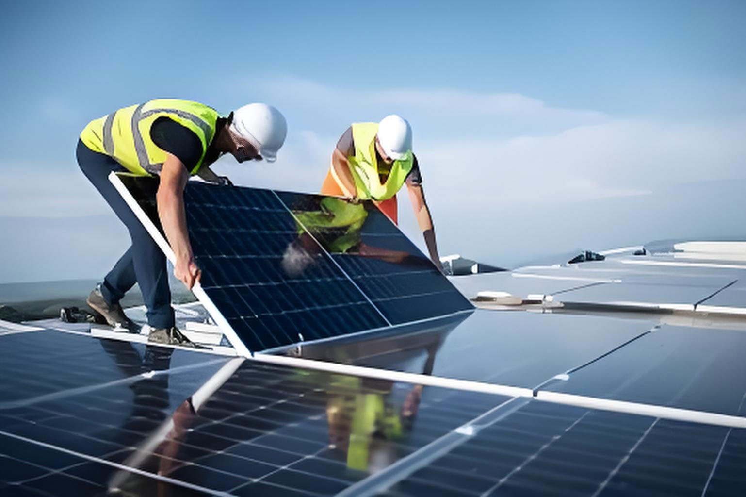
With the global consensus on carbon peaking and carbon neutrality, solar power generation has become one of the key technologies for reducing carbon emissions. However, during the operation of solar power plants, dust gradually accumulates on the surface of solar panels, which ultimately affects the reception of solar radiation by solar panels and results in a loss of power generation. Regular and effective cleaning of solar panels can significantly improve the power generation efficiency of solar power plants and is currently the mainstream approach to enhancing photoelectric conversion efficiency.
Currently, many domestic solar power plants still rely on manual or semi-automatic cleaning methods. Manual cleaning is inefficient, costly for large-scale power plants, and leads to severe water waste. Semi-automatic cleaning often involves using heavy machinery driven by humans, which, although more efficient, is complex to operate and has strict terrain requirements, making it unable to clean rooftop or densely arranged solar panel arrays. For automated cleaning technologies suitable for various solar panel installation environments, the currently more mature option is the rail-mounted automatic cleaning robot. It moves and cleans along pre-installed rails on the frame of solar panels, but this cleaning method incurs high installation and maintenance costs. Therefore, in recent years, many industry experts and scholars have been dedicated to researching intelligent cleaning robots that can autonomously move and clean on solar panels. These robots are compact, lightweight, easy to transport, and suitable for various solar panel installation environments, representing the future mainstream of solar panel cleaning.
In response to the significant economic losses caused by dust on solar panels in solar power plants and the shortcomings of existing cleaning technologies, this paper designs an intelligent cleaning robot for solar panels based on the installation environment of solar panels. Through theoretical calculations and prototype performance tests, the robot can autonomously clean solar panels, reducing labor costs and water waste.
2. Structure Design of the Intelligent Cleaning Robot for Solar Panels
2.1 Overall Design of the Robot
The cleaning robot mainly consists of a walking mechanism, a cleaning mechanism, a control module, and various sensors.
| Component | Description |
|---|---|
| Walking Mechanism | Enables the robot to move on the solar panel |
| Cleaning Mechanism | Removes dust and dirt from the solar panel surface |
| Control Module | Controls the operation of the robot |
| Sensors | Provide information about the robot’s position and the environment |
2.2 Design of the Walking Mechanism
Due to the smooth surface of the solar panel and the gaps between panels, to ensure the stable operation of the robot, a synchronous wheel walking mechanism is adopted. The walking mechanism is composed of synchronous wheels, a synchronous belt, a driving motor, and other components. There are four synchronous wheels on each side of the robot. The advantages of this design are as follows: the synchronous belt is made of soft material and has a large contact area with the solar panel. Under the same material friction coefficient, it increases the friction with the solar panel, and the large contact area also enhances the stability of the robot when crossing gaps. Additionally, the robot can turn in place by simply reversing the rotation of the driving motor.
To prevent the synchronous belt from slipping, the driving torque of the driving wheel should satisfy the following equation:
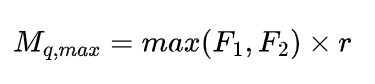
where F1 and F2 are the driving forces of the left and right synchronous wheels (N), respectively, and γ is the pitch circle radius of the driving wheel.
To balance the cleaning efficiency and quality of the robot, the initial running speed of the robot is set to 0.2 – 0.4 m/s. Based on the calculation results of the above equation, the models of the driving motor and reducer of the robot’s walking mechanism can be determined.
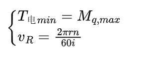
where T电min is the minimum torque of the driving motor (N·m), is the running speed of the robot (m/s), is the rotational speed of the robot’s driving motor, and is the reduction ratio of the robot’s driving motor.
2.3 Design of the Cleaning Mechanism
Since solar panels are exposed outdoors for a long time, the main pollutant attached to them is dust. Analyzing the attachment mechanism between dust particles and the solar panel is beneficial for selecting an appropriate cleaning mechanism.
2.3.1 Van der Waals Force between Dust and Solar Panel
Based on the contact model of soil particles and solid surfaces summarized by Jia Xian et al., the expression for the Van der Waals force between dust particles and the solar panel surface without considering contact deformation is obtained as follows:
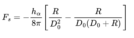
where hm is the Lifshitz constant, with a value range of 0.96 – 1.44 eV, R is the radius of the dust particle (m), and D0 is the average distance between molecules when the dust particle is in close contact with the solar panel surface (m).
2.3.2 Electrostatic Force between Dust and Solar Panel
The expressions for the contact electrostatic force and the double-layer electrostatic force of dust adhering to the solar panel surface summarized by Bowling are as follows:
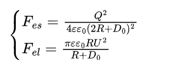
where Fes is the contact electrostatic force (N), Fel is the double-layer electrostatic force (N), Q is the charge of the dust particle, ε is the dielectric constant of air (ε=1), ε0 is the absolute dielectric constant (ε0=8.85✖10^-12F/m), and U is the contact potential difference (m).
According to the research by Meng Guangshuang et al., by substituting different dust particle radii and intermolecular distances, the average value of the Van der Waals force on the dust on the solar panel is calculated to be in the range of (10^-11—10^-9)N, the contact electrostatic force on the dust particle is generally not more than 10^-12N, and the average value of the double-layer electrostatic force is in the range of (10^-13—10^-12)N.
2.3.3 Design of the Cleaning Mechanism
The cleaning mechanism is composed of a roller brush, a roller brush motor, a water pump motor, a water tank, an atomizing nozzle, and other components. The roller brush is composed of bristles, a brush roller, and a PVC outer tube. To ensure no dead corners in cleaning and improve cleaning efficiency, the length of the roller brush should be greater than the distance between the two driving wheels. To ensure cleaning quality without damaging the tempered glass surface of the solar panel, the roller brush is made of nylon wire with a diameter of 0.15 mm. To adapt to the cleaning environment in areas with less or more water and more effectively remove scale and bird droppings adhered to the solar panel after drying, this cleaning robot is equipped with a water tank and a water pump, enabling both dry and wet cleaning modes.
Zhang Rupeng found through research that when the rotation speed of the roller brush is 1.5 times or more the moving speed of the robot, the roller brush has a better cleaning effect. Therefore, the rotational speed of the roller brush motor can be determined by the following equation:
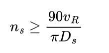
where Ds is the diameter of the brush roller.
Assuming the radius of the dust particle is 2 μm, the magnitude of the force required to remove the dust on a 1 m² solar panel covered with dust is in the range of 10-100N. Then, the appropriate contact pressure FN between the roller brush and the solar panel can be calculated by the following equation:
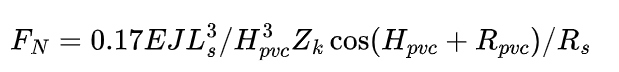
where E is the elastic modulus of the bristle material, J is the polar moment of inertia of the bristle crosssection, Ls is the free length of the bristle, Hpvc is the vertical distance from the lower end of the PVC tube to the solar panel, Zk is the number of bristles in contact with the solar panel, Rpvc is the radius of the PVC tube, and Rs is the radius of the brush roller.
The minimum traction force Ft required by the roller brush to remove dust is:
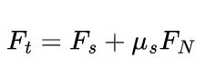
where Fs is the friction force between the bristles and the dust during cleaning (N), and μs is the friction coefficient between the bristles and the solar panel.
Finally, the torque Mn required by the roller brush driving motor can be obtained as follows:
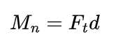
where is the radius of the roller brush (m), d=Ls+Rs.
3. Stability Analysis of the Intelligent Cleaning Robot for Solar Panels
Due to the inclined installation of solar panels, the smooth surface of the tempered glass on the upper surface of the panel, the small friction, and the gaps between adjacent panels, to ensure that the robot can stably walk and complete the cleaning task on the solar panel, a synchronous belt wheel is selected as the walking mechanism of the robot. At the same time, by analyzing the motion stability of the robot, the mass and size of the robot can be further determined. oxyz is the moving coordinate system fixed at the geometric center of the robot. The longitudinal direction of the robot is the x-axis, the transverse direction is the y-axis, and the z-axis is perpendicular to the motion plane of the robot. OXYZ is the inertial coordinate system, the direction of the λ-axis is consistent with the normal direction of the solar panel, γ is the inclination angle of the solar panel, ψ is the yaw angle of the robot, that is, the angle between the longitudinal direction of the robot and the horizontal axis X of the inertial coordinate system. Assuming the robot is a rigid body and ignoring air resistance.
3.1 Anti-slip Stability Analysis
From the force balance of the cleaning robot in the Y-axis direction, we have:
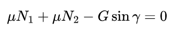
where μ is the friction coefficient between the solar panel and the synchronous belt of the robot, and , are the reverse support forces of the solar panel on the left and right walking mechanisms of the robot (N).
3.2 Anti-tipping Stability Analysis
From the force balance of the cleaning robot in the z-axis direction and the moment balance of the two synchronous wheels with respect to the geometric center of the robot, we have:
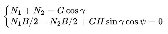
where B is the distance between the left and right synchronous wheels of the robot (m), and H is the height of the center of mass of the robot. By solving these two equations simultaneously, the expressions for N1 and N2 can be obtained as follows:
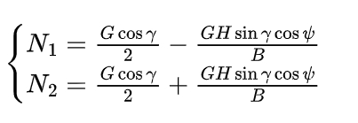
To ensure that the robot does not tip over in any pose on the solar panel, both the left and right synchronous wheels should be in contact with the solar panel surface, that is,(N1,N2)≥0 .
3.3 Straight-line Motion Stability Analysis
When the robot moves in a straight line on the solar panel, the friction force between the synchronous belt and the solar panel surface provides the driving force for the robot. From the force balance in the longitudinal direction of the robot, we have:
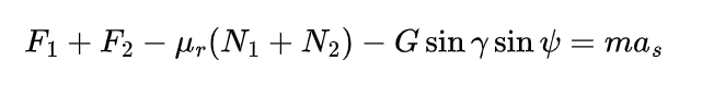
where is the friction resistance coefficient between the synchronous belt and the solar panel.
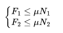
The driving force generated by the walking mechanism of the robot is limited by the properties of the solar panel and the parameters of the robot, that is:
3.4 Turning Motion Stability Analysis
When the robot reaches the edge of the solar panel, it needs to turn and adjust its direction to continue the cleaning work. Therefore, it is also necessary to analyze the stability during the turning process. To ensure no dead corners in cleaning and safety, the robot turns in place using differential steering without considering the axial offset and center of gravity offset during turning. Taking a left turn in place as an example, the steering resistance moment is:
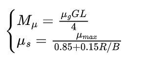
where Mμ is the steering resistance moment (N·m), μs is the steering resistance coefficient, μmax is the steering resistance coefficient during sharp turns, and R is the turning radius. When turning in place, R=B/2.
When the turning radius is B/2, the synchronous belts on both sides of the robot are subject to the ground friction resistance in the opposite direction. The force balance equations for the inner and outer synchronous belts are:
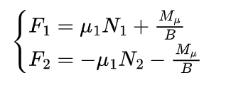
The driving force is also limited by the properties of the solar panel and the parameters of the robot and should satisfy the above equation.
4. Control System Design of the Intelligent Cleaning Robot for Solar Panels
To enable the cleaning robot to automatically complete the cleaning work of solar panels, its control system should include a core control module, a walking drive module, a cleaning control module, a sensing module, a communication module, and a power supply module.
Considering that the control system of the cleaning robot involves multiple motor controls and the collection and calculation of various sensor information, the main control chip of the robot is selected as the STM32F103ZET6 chip. The chip has a maximum working frequency of 72 MHz, 8 timers, and can realize PWM signal output and incremental encoder input operations. In addition, the chip is equipped with rich IO interfaces and communication interfaces, meeting all the functional requirements of the cleaning robot.
4.1 Design of the Walking Drive Module and Cleaning Control Module
In the above design calculations, the torque and rotational speed of the motors of the walking mechanism and cleaning mechanism have been determined. Based on this, the motor model of the walking mechanism is determined to be ZY4278R3, and the reduction ratio of the reducer is 1:51. The motor model of the cleaning mechanism is 5840 – 31ZY, and the reduction ratio of the reducer is 1:31. The water pump motor can be selected with appropriate pressure and flow. This robot selects the 755 – 6 self-priming diaphragm pump. Since the maximum voltage generated by the core control module is only 5 V, which cannot directly control the motors, the motor driver ATK – PD6010D is selected to supply power to the motors and realize the functions of forward and reverse rotation and PWM speed regulation of the motors.
4.2 Design of the Sensing Module
To enable the cleaning robot to move autonomously on the solar panel, it should have the ability to sense its own state and the external environment. The sensing module of the robot is composed of a gyroscope, an accelerometer, an encoder, a photoelectric sensor, etc. Through the data fusion of the gyroscope, accelerometer, and encoder, the position of the robot on the solar panel is obtained, and the photoelectric sensor distributed at the front end of the robot detects the edge of the solar panel in real time to prevent the robot from falling. In addition, the water level sensor and battery level sensor detect the water level and battery level of the robot in real time to ensure the normal operation of the robot.
4.3 Design of the Communication Module
To obtain the working status of the robot in real time, the robot is equipped with a wireless module ATK – BLE02 with a data transmission frequency of 2.4 GHz and a maximum transmission rate of 1 Mb/s. By configuring the data transmission protocol between the upper computer and the Bluetooth module, communication between the upper computer and the robot is established. On the one hand, the upper computer can send commands to control the movement of the robot; on the other hand, the robot can send status information to the upper computer in real time.
4.4 Design of the Power Supply Module
Since the working voltages of the hardware carried by the robot are inconsistent and their adaptability to the power supply voltage is different, considering comprehensively, a 24 V, 60 A·h lithium battery with a capacity of 20,000 mA·h is selected. The battery can be disassembled and charged when the robot runs out of power. At the same time, a voltage stabilization and step-down module LM2596S is equipped to ensure the normal operation of all hardware.
4.5 Control Strategy Design
4.5.1 Cleaning Path Design
To minimize energy consumption, first, the heading angle standard for the robot’s movement on the solar panel is set. The movement direction of the robot is judged by adjusting the heading angle. After the robot is placed at the corner of the solar panel, it moves and cleans according to the optimal cleaning path. The cleaning trajectory of the robot. The cleaning work of the robot is divided into the following steps:
(1) After the robot is successfully placed, it moves in a straight line. When a gap is detected, it continues to move forward until it detects the edge of the solar panel and then stops moving.
(2) Adjust the heading angle to 90° and move straight for one parking space.
(3) Adjust the robot’s heading angle to 180°, and the robot continues to move forward in a straight line until it detects the next edge.
(4) The robot repeats the above instructions until the cleaning work is completed.
4.5.2 Control Software Design
The cleaning robot software is programmed in C language on the Keil – μVision platform. The program design includes main program design, subroutine design, and communication program design. The subroutines include motor drive program, PWM output program, sensor data receiving and processing program, etc. Since the robot control program is numerous, after the individual programs are debugged successfully, the overall debugging of the entire set of programs should be carried out. The program priority is set to ensure the operation efficiency of the robot and avoid situations such as system crashes. After debugging, the program is burned into the STM32 development board.
5. Development and Testing of the Intelligent Cleaning Robot for Solar Panels
After the theoretical analysis, structure design, and control system design of the cleaning robot, to verify the design effect, a prototype of the solar panel cleaning robot is developed and tested. Before the test, the relevant work includes the processing of the mechanical structure of the robot chassis, the connection of the control hardware circuit, the burning of the software program, and the assembly of the whole machine.
5.1 Robot Motion Stability Test
Due to the limitations of test conditions, the stability test is carried out on a smooth tempered glass surface with different slopes. The slopes of the tempered glass are set to 5°, 15°, and 25° respectively, and the robot is placed on the glass surface to control its walking. The test results show that the robot can stably operate on a smooth plane with a slope of less than 25°.
5.2 Robot Cleaning Ability Test
Due to the geographical differences in the distribution of solar power plants, the dust on solar panels can be divided into floating dust and scale. Therefore, during the test, dry sand and moist clay with adhesion are selected to test the cleaning ability of the robot. The test results show that the cleaning robot has a good cleaning effect on both dry sand and clay adhered to the solar panel.
5.3 Robot Cleaning Path Test
After testing the various performances of the robot, the overall operation effect of the robot is finally tested. The test site is a platform with a length of 2 m and a width of 1.4 m. The robot is placed at the starting point, and the automatic cleaning mode is turned on. After the robot starts from the placement point, it moves according to the optimal cleaning path set by the program. Finally, when the robot adjusts the heading angle to 90° and still detects the edge, it is determined that the cleaning work is completed. After multiple tests, it takes about 33 s for the robot to complete the operation. Therefore, the cleaning efficiency of the robot can be calculated as 2 m²/h.
6. Conclusion
In response to the problem of reduced photoelectric efficiency caused by dust on solar panels, an intelligent cleaning robot for solar panels is designed. Firstly, the structure design and motion stability analysis of the robot are carried out. Then, the control system of the robot is designed according to the functions to be realized. Finally, a physical prototype is prepared for performance testing. The test results show that the robot can stably operate on solar panels with a maximum slope of 25°, has a certain cleaning ability for floating dust or scale stains, and can move on the plane according to the specified path. The test fully verifies the correctness of the robot’s structure design and motion stability analysis. In addition, compared with traditional cleaning technologies, under the premise of ensuring cleaning efficiency and quality, the labor cost is greatly reduced, and the waste of water resources is reduced.